Keysight Technologies M8000 Series Getting Started Manual
Ber test solutions, high-performance bert
Hide thumbs
Also See for M8000 Series:
- User manual (668 pages) ,
- Installation manual (78 pages) ,
- Manual (32 pages)

Related Manuals for Keysight Technologies M8000 Series


Summary of Contents for Keysight Technologies M8000 Series
- Page 1 Keysight M8000 Series of BER Test Solutions M8040A High-Performance BERT Getting Started Guide...
- Page 2 BE LIABLE FOR ERRORS OR FOR INCIDEN- agreement and written consent from disclose the Software. The EULA and the TAL OR CONSEQUENTIAL DAMAGES IN Keysight Technologies as governed by license set forth therein, does not require CONNECTION WITH THE FURNISHING, United States and international copyright...
-
Page 3: Safety Summary
Failure to comply with these precautions or with specific warnings or operating instructions in the product manuals violates safety standards of design, manufacture, and intended use of the instrument. Keysight Technologies assumes no liability for the customer's failure to comply with these requirements. Product manuals are provided with your instrument on CD-ROM and/or in printed form. - Page 4 Safety Symbols Table 1 Safety Symbol Symbol Description Indicates warning or caution. If you see this symbol on a product, you must refer to the manuals for specific Warning or Caution information to avoid personal injury or damage to the product. Frame or chassis ground terminal.
- Page 5 Symbol Description CSA is the Canadian certification mark to demonstrate compliance with the Safety requirements. CE compliance marking to the EU Safety and EMC Directives. ISM GRP-1A classification according to the international EMC standard. ICES/NMB-001 compliance marking to the Canadian EMC standard.
-
Page 6: Compliance And Environmental Information
Compliance and Environmental Information Table 2 Compliance and Environmental Information Safety Symbol Description This product complies with WEEE Directive (2002/96/EC) marking requirements. The affixed label indicates that you must not discard this electrical/electronic product in domestic household waste. Product Category: With reference to the equipment types in WEEE Directive Annex I, this product is classed as a “Monitoring and Control instrumentation”... -
Page 7: About This Guide
If you ordered a system that requires on-site installation of individual M8000 modules or the M9537A AXIe Embedded Host Computer into the M9505A AXIe Chassis, refer to the Keysight M8000 Series of BER Test Solutions Installation Guide for detailed module-level installation instructions. -
Page 9: Table Of Contents
Contents Safety Summary Compliance and Environmental Information About This Guide 1 Introduction Introduction Key Features Applications M8040A Modules M9505A AXIe Chassis AXIe Embedded System Module (USB ESM) Keysight M9537A AXIe Embedded Controller Module Host Computer M8045A High-Performance BERT Pattern Generator-Clock Module M8045A Features M8045A Module Components... - Page 10 Step 8 - Install M8070A Software (not required for M8040A-BU1) Step 9 - Install the Licenses Installing M8070A-0TP License (not required for M8040A-BU1) Installing Temporary License (Trial License) for the M8000 Series Installing M8070A-0NP Floating/Networked License Installing the FlexNet License Manager Installing Module Licenses (for upgrades only)
- Page 11 Contents 3 Using the M8040A High-Performance BERT Locating Electronic Manuals and Online Help Routine Care Starting the M8070A Software Perform a Measurement Updating Software Components Contacting Keysight Service and Support Quick Troubleshooting Index Keysight M8040A High-Performance BERT Getting Started Guide...
-
Page 13: Introduction
Keysight M8040A High-Performance BERT Getting Started Guide Introduction / 14 Introduction / 16 M8040A Modules / 21 M8045A High-Performance BERT Pattern Generator-Clock Module / 25 M8046A High-Performance BERT Analyzer Module / 28 M8057A Pattern Generator Remote Head This chapter introduces you to Keysight’s M8040A High-performance BERT. -
Page 14: Introduction
Introduction Introduction The Keysight Technologies M8040A is a highly integrated BERT for physical layer characterization and compliance testing. With support for pulse amplitude modulation 4-level (PAM-4) and non-return-to-zero (NRZ) signals, and symbol rates up to 64 GBaud (corresponds to 112 Gbit/s) it covers all flavors of the emerging 400 GbE and CEI-56G standards. - Page 15 Introduction • 64G/112G Fibre Channel • Infiniband-HDR • Proprietary interfaces for chip-to-chip, chip-to-module, backplanes, repeaters, and active optical cables, operating up to 64 GBaud. Keysight M8040A High-Performance BERT Getting Started Guide...
-
Page 16: M8040A Modules
Introduction M8040A Modules The M8040A modules are recognized by the model number and name located on their front panel. Each of the supported modules has some standard hardware and software features that are available with a standard license for that module. Some upgraded features/components of a module are licensed and are only available when you purchase and install a license for that option. -
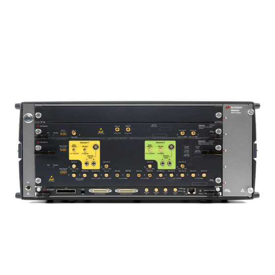
Page 17: M9505A Axie Chassis
Introduction Details on the features and hardware components of each of the above mentioned modules are further described in this chapter. M9505A AXIe Chassis The M9505A AXIe chassis is a modular instrument chassis that supports complex and high density testing. The chassis provides five slots for installing multiple AXIe based instrument modules such as the M8045A, M8046A, etc. -
Page 18: Axie Embedded System Module (Usb Esm)
Introduction AXIe Embedded System Module (USB ESM) The bottom slot of the AXIe chassis is reserved for the Embedded System Module (ESM) which is factory installed. The ESM has a USB 2.0 interface as well as a PCIe x8, Gen1 and Gen2 compliant interface to connect an external host computer to the chassis. -
Page 19: Keysight M9537A Axie Embedded Controller Module
Introduction The ESM: • runs the chassis embedded operating system (Windows 7) which manages all internal tasks and communications. • tracks inserted modules and manages power requirements. • monitors chassis temperature and controls variable- speed chassis fans. • monitors module sensors and reports component failures to a system log. -
Page 20: Host Computer
Introduction Host Computer A host computer is used to: • host all the software components of the instrument modules needed to control, configure, and use the modules. • communicate with the ESM of the M9505A AXIe chassis to allow you to monitor and control the chassis. -
Page 21: M8045A High-Performance Bert Pattern Generator-Clock Module
Introduction M8045A High-Performance BERT Pattern Generator-Clock Module The M8045A is an instrument module that can be installed into the M9505A 5-slot AXIe Chassis. This module occupies three slots. M8045A Features • Up to two Pattern Generator channels per 2-slot-module • Symbol rate 2 to 64.8 GBaud •... - Page 22 Introduction As displayed in Figure 5 on page -21, the M8045A module has the following components. Table 3 Insertion/Extraction and Retaining Component Description Retaining screws The screws on both ends of the module are used to retain the module tightly inside the M9505A AXIe Chassis slot once you have fully placed it inside the chassis.
-
Page 23: M8045A Front Panel Input/Output Ports
Introduction Connector Name Active when... Color Clk Mod In input is active green Sys Out A/Sys Out B output is active green Sys In A/Sys In B logic state is detected green M8045A Front Panel Input/Output Ports The inputs of the M8045A module are sensitive to static electricity. CAUTION Therefore, take necessary anti-static precautions, such as wearing a grounded wrist strap, to minimize the possibility of electrostatic damage. - Page 24 Introduction Component Description CTRL IN A, B The data module has 2 control inputs at the front panel. The functionality of each individual input can be selected. • Error Add Input Every rising edge at the input generates a single error in the output stream by flipping a single bit.
-
Page 25: M8046A High-Performance Bert Analyzer Module
Introduction M8046A High-Performance BERT Analyzer Module The M8046A is an instrument module that can be installed into the M9505A 5- slot AXIe chassis. This module occupies two slots and requires the M8045A module for proper operation. The three or four channel configuration requires a cable (provided with NOTE the M8046A) that connects the M8045A SYNC OUT to the M8046A SYNC IN to synchronize the two modules to a common system clock. -
Page 26: M8046A Front Panel Inputs/Outputs Ports
Introduction As displayed in Figure 6 on page -25, the M8046A module has the following components. Table 6 Insertion/Extraction and Retaining Component Description Retaining screws The screws on both ends of the module are used to retain the module tightly inside the M9505A AXIe Chassis slot once you have fully placed it inside the chassis. - Page 27 Introduction Table 8 M8046A Front Panel Inputs/Outputs Ports Component Description Data In and /Data In Differential data inputs (3.5 mm, female) Clk In Clock input to sample the incoming data. Full/half and quarter-rate clock. Single ended. CTRL IN can be used as sequence trigger or pattern capture event.
-
Page 28: M8057A Pattern Generator Remote Head
Introduction M8057A Pattern Generator Remote Head The M8057A remote head is an external box which must be connected to each channel of M8045A module. The three cables are fixed on the back side of M8057A which need to be connected to M8045A remote head, P and N connectors. - Page 29 Introduction Table 10 M8057A Front Panel Inputs/Outputs Ports Component Description Data Out and /Data Out Connected to DUT The following figure displays the back panel of the M8057A remote head with its various components: Figure 8 M8057A remote head back panel As displayed in Figure 8 on page -29, the back panel of M8057A remote...
-
Page 31: Basic Setup For M8040A
Keysight M8040A High-Performance BERT Getting Started Guide Basic Setup for M8040A / 32 Step 1 - Unpack the Shipment / 33 Step 2 - Set up the M8040A Step 3 - Set up the External Host Computer (not required for / 33 M8040A-BU1) / 36... -
Page 32: Step 1 - Unpack The Shipment
Basic Setup for M8040A Step 1 - Unpack the Shipment The M8040A-BU1 or M8040A-BU2 is shipped with the modules pre- installed in the M9505A AXIe Chassis. Unpack and verify the shipment contents to check if you have received all the items that you ordered. The shipment contents can vary depending on the options that you ordered. -
Page 33: Repair/Replacement
Basic Setup for M8040A Return the Damaged/Defective Item to Keysight for Repair/Replacement If anything is missing, defective, or damaged, Review the warranty information shipped with your product or check the warranty information on Keysight website. • To check the warranty information on your module, go to www.keysight.com/find/warranty and specify the module’s model number (for example, M8045A) in the Product Number field, and... -
Page 34: Computer Hardware And Software Requirements
Basic Setup for M8040A Computer Hardware and Software Requirements The following are the hardware and software requirements that should be met on the host computer before the installation of software components on this computer: Hardware requirements • Pentium® processor 1 GHz or equivalent •... -
Page 35: To Connect Via Usb
Basic Setup for M8040A To connect via USB If you are planning to use USB connectivity between the M9505A AXIe Chassis and host computer, then you can use a laptop or desktop computer with USB 3.0 support as the host computer. USB Port Figure 9 USB port on the font panel of the AXIe ESM... -
Page 36: Step 4 - Connect The M9505A Axie Chassis To A Power Supply
Basic Setup for M8040A Step 4 - Connect the M9505A AXIe Chassis to a Power Supply You can use an external power supply, typically AC power mains. The instrument module uses the power supplied by the M9505A AXIe Chassis in which it is installed. The M9505A AXIe Chassis power cord comes with the chassis shipment. -
Page 37: Step 5 - Power Up (If Connecting Via Pcie)
Basic Setup for M8040A Step 5 - Power Up (if connecting via PCIe) Power up all the connected hardware components in the M9505A AXIe Chassis. Press the ON/Standby button on the front panel of the chassis to power on the chassis. Figure 12 Chassis ON/standby button After powering up the chassis, wait until the Status LED of the ESM is... -
Page 38: Step 6 - Verify Basic M8040A Operation
Basic Setup for M8040A To power down a chassis, first turn off the host computer and then power NOTE down the chassis using the On/Standby button on its front panel. If you are using the M9537A AXIe Embedded Controller module as the host computer, ensure that you first shut down the controller by executing the Windows shutdown process. -
Page 39: Step 7 - Install Keysight Io Libraries Suite (Not Required For M8040A-Bu1)
Basic Setup for M8040A Step 7 - Install Keysight IO Libraries Suite (not required for M8040A-BU1) IO Libraries Suite version 16.3 or later is required. Always use the latest version of the Keysight IO Libraries. Perform this step if you are setting up an M8040A-BU2 system or the NOTE host computer you are using as part of the M8040A system requires I/O library installation. -
Page 40: Step 9 - Install The Licenses
Basic Setup for M8040A To install the software Insert the CD ROM into the host computer or download the latest M8070A software from www.keysight.com/find/M8040A. Double-click the setup (.exe) file. The InstallShield Wizard is displayed. If displayed, click Install to continue or click Next if the system controller meets the minimum system configuration requirements displayed by the wizard. -
Page 41: Installing M8070A-0Tp License (Not Required For M8040A-Bu1)
Utilities > Licenses... then viewing the license status in the Installed column. Installing Temporary License (Trial License) for the M8000 Series A temporary (trial) license differs from the perpetual license in a way that it has an expiration date. These licenses are typically provided at no charge for evaluation of new functionality that is licensed. -
Page 42: Installing M8070A-0Np Floating/Networked License
Basic Setup for M8040A Installing M8070A-0NP Floating/Networked License An M8070A-0NP floating/networked license resides on a network server and is accessible by multiple users. The user checks out a license each time the software is accessed. The server tracks the number of licenses checked out and the number of licenses available for use. -
Page 43: Installing The Flexnet License Manager
Basic Setup for M8040A Click Change Settings. You may need to provide an administrator password or provide confirmation for this action. Click on the Allow another program button. Figure 14 Select program Select M8000 then click Add. Add program path: C:\Program Files (x86)\FlexNet Publisher License Server Manager\ lmadmin.exe. - Page 44 Basic Setup for M8040A Imadmin Installation The following procedure describes how to install lmadmin.exe (server side): Copy the agilent.lic file from the Keysight Licensing installation path (typically found in, C:\Program Files\Agilent\ACCL\Licensing\bin or C:\Program Files (x86)\Agilent\\ACCL\Licensing\bin) into the licensing folder. (The license filename will change to agilent0.00.lic after successful installation.) Determine whether the target system has Java installed, if not, install it from www.java.com.
- Page 45 Basic Setup for M8040A 10 Login to the lmadmin web configuration page. Add the agilent.lic and the M8070A-0NP. C:\Program Files (x86)\Agilent\ACCL\Licensing\bin\agilent.lic …\1001562893_1166729.lic 11 On the client side, install the M8070A software on the client PC. 12 Install the edited license M8070A-0NP on the client (import license in the Keysight License Manager).
- Page 46 Licenses on page 46. Acquiring Floating Licenses Contact your Keysight Technologies representative to purchase licenses for your software. You will receive an order number and certificate number, which you will use to request a license file in step 3. Select and configure your license server machine as described above.
- Page 47 Basic Setup for M8040A When you receive your license via e-mail from Keysight Technologies, carefully read the instructions sent with the license. If the license is a "served" or "floating" license, put it in the directory C:\Program Files\ Agilent\licensing on the license server.
- Page 48 Basic Setup for M8040A 10 Change the Vendor Daemon Location (which is blank) to the location of the Agilent.exe file: a For 32- bit Windows, enter “C:\Program Files\Agilent\ACCL\ Licensing\bin\Agilent.exe”. b For 64- bit Windows, enter “C:\PROGRA~2\Agilent\ACCL\ Licensing\bin\Agilent.exe”. For 64-bit Windows, the file is in “C:\Program Files (x86)”, but the Web NOTE page does not allow you to enter a file path containing an open or close parenthesis, so you must instead enter the short file name...
-
Page 49: Installing Module Licenses (For Upgrades Only)
Basic Setup for M8040A Install the client floating license files. a Start the Keysight License Manager by double clicking the Keysight License Notifier icon or click Start > All Programs > Keysight License Manager > Keysight License Manager. b To install the license file, drag-and-drop the license file onto the Keysight License Manager “License Features”... -
Page 50: Transporting An M8070A License
Basic Setup for M8040A Follow the instructions in the email to complete the installation of the license file. In the M8070A software interface, verify that the license has been installed by selecting Utilities > Licenses then viewing the license status in the Installed column. Transporting an M8070A License Transportable licenses are licenses that can be moved from one host controller to another using the Keysight License Manager. - Page 51 Basic Setup for M8040A Figure 15 Option label sheet Locate the option label sheet shown in Figure 15 on page -51. Affix the option labels as shown in Figure 16 on page -51. Option Labels Figure 16 Affix option labels Keysight M8040A High-Performance BERT Getting Started Guide...
-
Page 52: Step 10 - Turning Off The Chassis And Modules
Basic Setup for M8040A Step 10 - Turning off the Chassis and Modules Turn off the chassis and module in the following sequence: Turn off the host computer. If you are using the Keysight AXIe Embedded Controller module as the host computer, ensure that you shut down the controller by executing the Windows shutdown process. -
Page 53: M9537A Embedded Controller Setup Example
Basic Setup for M8040A In the CLK/2 mode, for symbol rates above 25 GBaud, an external NOTE bandpass filter has to be used on the clock input of M8046A. The filter has to be removed for symbol rates below 25 GBaud. However, in the CLK/1 mode, no external bandpass filter is required. -
Page 54: Hardware Connections
Basic Setup for M8040A Hardware Connections Make the hardware connections as described below: • Connect the M8057A to M8045A channel 1 remote head control. • Connect the M8057A to M8045A channel 1 remote head controls (P and N). • Ensure that the chassis is NOT powered up or connected to a power source while making connections to M8057A. -
Page 55: Using The M8040A High-Performance Bert
Keysight M8040A High-Performance BERT Getting Started Guide Using the M8040A High-Performance BERT / 56 Locating Electronic Manuals and Online Help / 56 Routine Care / 57 Starting the M8070A Software / 58 Perform a Measurement / 66 Updating Software Components / 66 Contacting Keysight Service and Support / 66... -
Page 56: Locating Electronic Manuals And Online Help
Using the M8040A High-Performance BERT Locating Electronic Manuals and Online Help Various electronic manuals and the M8070A Online Help provide information on how to configure and use the supported instrument modules. On installing the M8070A software, you will find documentation by clicking Start >... -
Page 57: Starting The M8070A Software
Using the M8040A High-Performance BERT The enclosure surface of the module may become hot during use. If you CAUTION need to remove the module, first power down the AXIe chassis, allow the module to cool, and then pull the module out of the chassis. For preventing damage, for usage tips, and for ESD information, read NOTE and follow the instructions in the “Tips for Preventing Damage Guide”... -
Page 58: Perform A Measurement
Using the M8040A High-Performance BERT Figure 20 M8070A user interface Perform a Measurement The following measurement example verifies a BER of 0 in channel 1 of the M8045A, M8046A and M8057A. Connect M8045A CLK OUT of Channel 1 to M8046A CLK IN. Connect DATA OUT of Remote-Head M8057A, which is connected to Channel 1 of M8045A, to the DATA IN of M8046A. - Page 59 Using the M8040A High-Performance BERT Figure 21 Synthesizer parameters c In the Synthesizer parameters, click in the numeric field corresponding to the Frequency setting. d Using the numeric keypad, enter 10 then click on the GHz button as shown in Figure 22 on page -59.
- Page 60 Using the M8040A High-Performance BERT On the menu bar, click on Patterns > Select Pattern..A Select Sequence Pattern dialog will appear as shown in Figure 23 page -60. Figure 23 Select Sequence Pattern Dialog In the Select Sequence Pattern dialog, select Prbs as the Pattern Type and then select 2^9- 1 as the Polynomial as shown in Figure 24 on page -61.
- Page 61 Using the M8040A High-Performance BERT Figure 24 Select PRBS and Polynomial Once done, click on Apply button. Now, click on the Modules View tab. Click on Channel 1 > Data Out corresponding to the M8045A (M1) as shown in Figure 25 on page -61.
- Page 62 Using the M8040A High-Performance BERT 11 Click on Data Out corresponding to the M8045A (M1) and select the line coding PAM-4. Figure 26 Select line coding 12 Click on Clk Gen corresponding to the M8045A (M1) and set the frequency as 10 GHz. In the CLK/2 mode, for symbol rates above 25 GBaud, an external NOTE bandpass filter has to be used on the clock input of M8046A.
- Page 63 Using the M8040A High-Performance BERT 15 Enable the global outputs by clicking on the Output button present on the Status Bar as shown in Figure 28 on page -63. Figure 28 Enable global outputs 16 Click on Data In corresponding to the M8046A(M2) as shown in Figure on page -63.
- Page 64 Using the M8040A High-Performance BERT 20 From the menu bar, click on Measurements > Error Ratio. 21 The default acquisition parameter settings are used as shown in Figure on page -64. Figure 31 Acquisition parameter settings 22 Click on the Start Measurement button to start the measurement as shown in Figure 32 on page -64.
- Page 65 Using the M8040A High-Performance BERT 23 After the measurement has completed (60 sec), review the results shown below the graph in the Calculated Results table as shown in Figure 33 on page -65. Figure 33 Calculated results Keysight M8040A High-Performance BERT Getting Started Guide...
-
Page 66: Updating Software Components
Using the M8040A High-Performance BERT Updating Software Components Updated versions of the M8070A and module specific software components are available on the Keysight website. These software components are available as .EXE files. To download a software upgrade: Go to http://www.keysight.com/find/m8070a Click the Technical Support tab. - Page 67 Using the M8040A High-Performance BERT A module is exceptionally hot • Check that the vent holes on the chassis are not blocked. • Check that a filler panel module or an instrument module is installed into empty slots on either side of an instrument module. The host computer is not getting connected to the chassis via PCIe •...
-
Page 69: Index
Index Numerics M8070A license transport, M8070A Software, M8070A Software, install, 5-slot AXIe chassis, labels, option, M8070A Software, starting, LAN connection, M8070A-0NP license, LEDs M8070A-0TP license, Access, 22, M9505-00230, Aux In, AXIe chassis, M9505A, Clk In, M9505A, power down, Clk Out, M9505A, power up, Ctrl In A, M9537A,... - Page 70 Index safety summary, Sync In, transport M8070A license, USB connectivity, 17, Keysight M8040A High-Performance BERT Getting Started Guide...
- Page 72 This information is subject to change without notice. © Keysight Technologies 2017 Edition 4.0, June 2017 Printed in Germany www.keysight.com...
Need help?
Do you have a question about the M8000 Series and is the answer not in the manual?
Questions and answers