Keysight Technologies M8000 Series User Manual
Ber test solutions
Hide thumbs
Also See for M8000 Series:
- Installation manual (78 pages) ,
- Getting started manual (72 pages) ,
- Manual (32 pages)

Related Manuals for Keysight Technologies M8000 Series


Summary of Contents for Keysight Technologies M8000 Series
- Page 1 Keysight M8000 Series of BER Test Solutions J-BERT M8020A High-Performance BERT M8030A Multi-Channel BERT M8040A High-Performance BERT User Guide...
- Page 2 ALL WARRANTIES, EITHER EXPRESS OR its standard commercial license, which is met. IMPLIED WITH REGARD TO THIS MANUAL embodied in its End User License Agree- AND ANY INFORMATION CONTAINED Keysight M8000 Series of BER Test Solutions User Guide...
-
Page 3: Safety Summary
Failure to comply with these precautions or with specific warnings or operating instructions in the product manuals violates safety standards of design, manufacture, and intended use of the instrument. Keysight Technologies assumes no liability for the customer's failure to comply with these requirements. Product manuals are provided with your instrument on CD-ROM and/or in printed form. - Page 4 Safety requirements. CE compliance marking to the EU Safety and EMC Directives. ISM GRP-1A classification according to the international EMC standard. ICES/NMB-001 compliance marking to the Canadian EMC standard. Keysight M8000 Series of BER Test Solutions User Guide...
-
Page 5: Compliance And Environmental Information
“Monitoring and Control instrumentation” product. Do not dispose in domestic household waste. To return unwanted products, contact your local Keysight office, or see http://about.keysight.com/en/companyinfo/environment/takeback.shtml for more information. Keysight M8000 Series of BER Test Solutions User Guide... -
Page 6: About This Guide
This chapter describes the utilities provided by the M8070A system software. Licenses This chapter provides information on the M8020A/M8030A/M8040A and M8070A licenses and their installation procedure. Appendix This chapter provides information about basic troubleshooting and factory patterns. Keysight M8000 Series of BER Test Solutions User Guide... -
Page 7: Table Of Contents
AXIe Embedded System Module (USB ESM) Host Computer M8030A Overview M9514A AXIe Chassis AXIe System Module (ASM) Keysight M9537A AXIe Embedded Controller Module M8020A / M8030A Modules J-BERT M8041A Generator-Analyzer-Clock Module M8041A Front Panel Connector Inputs/Outputs Keysight M8000 Series of BER Test Solutions User Guide... - Page 8 M8195A 65 GSa/s Arbitrary Waveform Generator M8196A 92 GSa/s Arbitrary Waveform Generator Other Supported Hardware(s) Keysight N1076A/N1077A DCA-M Clock Recovery Keysight Real Time Oscilloscopes Hardware Setup for M8046A and M8062A Modules Limitations ESD Protection Keysight M8000 Series of BER Test Solutions User Guide...
- Page 9 Parameters Window Creating Groups in the Module View System View Using the Zoom Tool Understanding the System View System View with M8061A Integration System View with M8062A Integration M8040A System View Keysight M8000 Series of BER Test Solutions User Guide...
- Page 10 Simultaneous Injection of CMSI and DMSI Using M819xA AWGs AWG as External Level Interference (RI/SI) Source System View with AWG(s) Integration Signal Generation in AWG Using AWG Frequency Response Calibration for Improved Signal Performance Selecting Line Coding Keysight M8000 Series of BER Test Solutions User Guide...
- Page 11 Best practices Remote controlling the real-time oscilloscope based error detector 5 Setting up Generator Overview M8020A/M8030A Generator Ports M8040A Generator Ports Understanding the Output Protection Circuit Understanding the Output Level Parameters Keysight M8000 Series of BER Test Solutions User Guide...
- Page 12 Common Mode Interference (CMI) Differential Mode Interference (DMI) Jitter Setup High Frequency Jitter (HF Jitter) Low Frequency Jitter (LF Jitter) Global Jitter State On/Off Switch How to Enable Global Jitter State Set Jitter Configuration Keysight M8000 Series of BER Test Solutions User Guide...
- Page 13 Pattern Synchronization Introduction to Pattern Synchronization What Type of Synchronization Should You Use? What is False Synchronization? How Can You Tell if Your Synchronization is False? How to Synchronize an Incoming Pattern Keysight M8000 Series of BER Test Solutions User Guide...
- Page 14 Modifying the Existing Sequences Sequence Setting Window Editing a Pattern in a Sequence Editor Sharing Sequences User-Defined Sequences Sequence Block Display Sequence Block Parameters Select Pattern Dialog Application Specific Patterns OIF CEI IEEE 802.3 Keysight M8000 Series of BER Test Solutions User Guide...
- Page 15 Link Training for USB 3.0 and USB 3.1 Using M8062A Data Out Squelch Feature Limitations Hardware Requirements Hardware Setup Software Usage 8 Working with Measurements Overview Exploring Measurement User Interface Launching the Measurement User Interface Toolbar Keysight M8000 Series of BER Test Solutions User Guide...
- Page 16 How to Run Output Timing Measurement How to Stop Output Timing Measurement Measurement Graph How an Output Timing Measurement Works Calculated Results Fast Total Jitter Measurement Results Calculated Results for Fast Total Measurement Keysight M8000 Series of BER Test Solutions User Guide...
- Page 17 How to Run Jitter Tolerance Measurement How to Stop/Abort Jitter Tolerance Measurement Measurement Graph Viewing the Jitter Tolerance Results Saving Jitter Tolerance Measurement Results Using the Jitter Tolerance Template Editor Template Editor Toolbar Template Editor Functions Keysight M8000 Series of BER Test Solutions User Guide...
- Page 18 Output Pane Console Settings Window Find and Replace Creating a Script Saving a Script Importing a Script Exporting a Script Running a Script Stopping a Script Adding Duplicate Row/Selection in the Code Keysight M8000 Series of BER Test Solutions User Guide...
- Page 19 SCPI Recorder Self Test Utility Launching the Self Test Utility Toolbar Self Test History Self Test Results Window Executing Self Test Aborting Self Test Saving Self Test Results Deleting Self Test Results Keysight M8000 Series of BER Test Solutions User Guide...
- Page 20 Supported Licenses Node-Locked (Uncounted) Licenses Floating Licenses Module-Specific Licenses M8020A/M8030A Licenses M8070A System Software for M8000 Series of BER Test Solutions M8041A - High-Performance BERT Module M8041A - License Upgrades for M8041A High-Performance BERT Module M8051A - High-Performance BERT Module...
- Page 21 Installing the Licenses Software Requirements Installing M8070A-OTP License (not required for M8020A-BU1 and M8030A-BU1) Installing Temporary License (Trial License) for the M8000 Series Installing M8070A-ONP Floating/Networked License Installing the FlexNet License Manager Creating a New License Service using lmadmin.exe Installing and Setting up Client PC Floating Licenses...
- Page 23 Keysight M8000 Series of BER Test Solutions User Guide Introduction / 24 J-BERT M8020A high-performance BERT / 25 M8030A Multi-Channel BERT / 26 M8040A High-Performance BERT / 28 Document History / 29 Related Documents / 29 Abbreviations used in this Document...
-
Page 24: Overview
8 tap de-emphasis, positive and negative • Integrated and adjustable Intersymbol Interference • Interactive link training for PCI Express • Built-in clock recovery and equalization • All options and modules are upgradeable Keysight M8000 Series of BER Test Solutions User Guide... -
Page 25: M8030A Multi-Channel Bert
PCIe and PON. Wherever multi-channel measurements are required in order to speed up throughput or test under real application conditions, the M8030A is a perfect solution. Figure 2 Typical base M8030A instrument configuration Keysight M8000 Series of BER Test Solutions User Guide... -
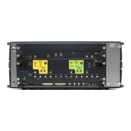
Page 26: M8040A High-Performance Bert
• XAUI and GAUI multi-lane test M8040A High-Performance BERT The Keysight Technologies M8040A is a highly integrated BERT for physical layer characterization and compliance testing. With support for pulse amplitude modulation 4-level (PAM4) and non-return-to-zero (NRZ) signals, and symbol rates up to 64 Gbaud (corresponds to 112 Gbit/s) it covers all flavors of the emerging 400 GbE and CEI-56G standards. - Page 27 • 64G/112G Fibre Channel • Infiniband-HDR • CDAUI-8 • Proprietary interfaces for chip-to-chip, chip-to-module, backplanes, repeaters, and active optical cables, operating up to 64 Gbaud. Figure 3 Typical M8040A instrument configuration Keysight M8000 Series of BER Test Solutions User Guide...
-
Page 28: Document History
Document History Edition Description Edition 1.0, June 2014 Edition 1.0 of the M8000 Series User Guide is in accordance to the M8070A version 1.0. Edition 2.0, October 2014 Edition 2.0 of the M8000 Series User Guide is in accordance to the M8070A version 1.5. -
Page 29: Related Documents
Introduction Edition Description Edition 11.0, December 2017 Edition 11.0 of the M8000 Series User Guide is in accordance to the M8070A version 4.5. Edition 12.0, June 2018 Edition 12.0 of the M8000 Series User Guide is in accordance to the M8070A version 5.0. - Page 30 Research & Development Serial Attached SCSI SATA Serial Advanced Technology Attachment SCPI Standard Commands for Programmable Instruments SubMiniature Version A Spread Spectrum Clock Transmission Control Protocol Universal Serial Bus Voltage Controlled Oscillator Keysight M8000 Series of BER Test Solutions User Guide...
-
Page 31: Know Your Hardware
Keysight M8000 Series of BER Test Solutions User Guide Know Your Hardware / 32 M8020A Overview / 33 M9505A AXIe Chassis / 35 Host Computer / 36 M8030A Overview / 37 M9514A AXIe Chassis / 40 M8020A / M8030A Modules... -
Page 32: M8020A Overview
M8020A modules, ensure that the AWG modules should be always be mounted in a slot number higher that M8020A modules in the AXIe chassis. In other words, an AWG module always has to mounted last in the chassis. Keysight M8000 Series of BER Test Solutions User Guide... -
Page 33: M9505A Axie Chassis
The PCIe connection is recommended for use with a desktop PC as an external controller only. Refer to the Keysight M9505A AXIe Chassis Startup Guide to get detailed information about the AXIe chassis. Keysight M8000 Series of BER Test Solutions User Guide... -
Page 34: Axie Embedded System Module (Usb Esm)
Either the PCIe (desktop only) or USB (desktop or laptop) port can be used in this ESM but not both simultaneously. When you use the PCIe port, the USB port is automatically disabled until the PCIe port is no longer in use. Keysight M8000 Series of BER Test Solutions User Guide... -
Page 35: Host Computer
M9505A AXIe Chassis. It is always installed in slot 1 of the M9505A AXIe Chassis. The following figure displays this module. Keysight M8000 Series of BER Test Solutions User Guide... -
Page 36: M8030A Overview
M8192A multi-channel synchronization module, always required in this slot For details on the features and hardware components of each of the above mentioned modules, refer to M8020A and M8030A Getting Started Guide. Keysight M8000 Series of BER Test Solutions User Guide... -
Page 37: M9514A Axie Chassis
PC controller is recommended when full channel plus large patterns need to be downloaded. Refer to the Keysight M9514A AXIe Chassis Startup Guide to get detailed information about the AXIe chassis. Keysight M8000 Series of BER Test Solutions User Guide... -
Page 38: Axie System Module (Asm)
Managing clocks, including internal or external reference sources. • Gigabit LAN switching with front panel RJ45 LAN connections. • AXIe Fabric 1 switching (Gen 2 x4 lanes to each module slot). Keysight M8000 Series of BER Test Solutions User Guide... -
Page 39: Keysight M9537A Axie Embedded Controller Module
Either the PCIe (desktop only) or USB (desktop or laptop) port can be used in this ESM but not both simultaneously. When you use the PCIe port, the USB port is automatically disabled until the PCIe port is no longer in use. Keysight M8000 Series of BER Test Solutions User Guide... -
Page 40: M8020A / M8030A Modules
Two channel pattern generator (option 0G2) and two channel error detector (option 0A2) • Data rate from 256 Mb/s to 16.2 Gb/s (option G16 or C16) for pattern generation and error detection • Built in jitter injection (option 0G3) Keysight M8000 Series of BER Test Solutions User Guide... - Page 41 Channel 1 Data Channel 2 Data Inputs/Outputs Inputs/Outputs Module Insertion/ Control Inputs/ Extraction Handles Output System Inputs/ Retaining Screws Outputs Clock Inputs/ Front Panel LEDs Outputs Sync In/Out Keysight M8000 Series of BER Test Solutions User Guide...
- Page 42 Clk Mod In input is active green Sys Out A/Sys Out B output is active green Sys Ctrl In A/Sys Ctrl In B logic level is detected green Keysight M8000 Series of BER Test Solutions User Guide...
-
Page 43: M8041A Front Panel Connector Inputs/Outputs
It can also be used as a sub rate clock. Clk Mod In Input for delay modulation of the Trig Out and Clk Out channel. Both outputs are always affected (SMA, female). Keysight M8000 Series of BER Test Solutions User Guide... - Page 44 This signal can be used to trigger an external instrument to help in error analysis. If an error occurs, a single RZ pulse is generated. Continuous errors will result in a clock signal. Keysight M8000 Series of BER Test Solutions User Guide...
-
Page 45: J-Bert M8051A Generator-Analyzer
The following figure displays the front panel of the M8051A module with its various components labeled. Channel 1 Data Channel 2 Data Inputs/Outputs Inputs/Outputs Module Insertion/ Control Inputs/ Extraction Handles Output Retaining Screws Front Panel LEDs Sync In Keysight M8000 Series of BER Test Solutions User Guide... - Page 46 The inputs of the M8051A module are sensitive to static electricity. CAUTION Therefore, take necessary anti-static precautions, such as wearing a grounded wrist strap, to minimize the possibility of electrostatic damage. Keysight M8000 Series of BER Test Solutions User Guide...
- Page 47 This signal can be used to trigger an external instrument to help in error analysis. If an error occurs, a single RZ pulse is generated with the width of half a vector length. Continuous errors will result in a clock signal. Keysight M8000 Series of BER Test Solutions User Guide...
-
Page 48: M8061A 32 Gb/S Multiplexer With De-Emphasis Module
Supports electrical idle • Control from J-BERT M8020A user interface via USB. M8061A Module Components The following figure displays the front panel of the M8061A module with its various components labeled. Keysight M8000 Series of BER Test Solutions User Guide... - Page 49 The handles on both sides of the module to insert or eject the module from the slot of the M9505A AXIe Chassis. Table 20 Front Panel LEDs Connector Name Active when... Color Fail power-up fault condition Access power-up ready state green Keysight M8000 Series of BER Test Solutions User Guide...
-
Page 50: M8061A Front Panel Connector Inputs/Outputs
Common mode interference input relative to ground (SMA, female). Table 24 Data Inputs/Outputs Component Description Data Out and /Data Out Differential or single-ended data output (2.4 mm, female). Data In x Single-ended data input (3.5 mm, female). Keysight M8000 Series of BER Test Solutions User Guide... -
Page 51: M8062A 32Gb/S Front-End For J-Bert M8020A High-Performance Bert
Phase-matched cables must be used when connecting the M8041A data NOTE and clock outputs to the M8062A data and clock inputs. The provided cable set, Keysight M8062-61643, meets this requirement. Keysight M8000 Series of BER Test Solutions User Guide... -
Page 52: M8062A Module Components
The inputs and outputs of the M8062A module are sensitive to static CAUTION electricity. Therefore, take necessary anti-static precautions, such as wearing a grounded wrist strap, to minimize the possibility of electrostatic damage. Keysight M8000 Series of BER Test Solutions User Guide... -
Page 53: M8062A Front Panel Pattern Generator Connectors
Differential Mode Interference input. Applies a single-ended, external interference source differentially to the data output (SMA, female). CMI In Common Mode Interference input. Applies a single-ended, external interference source to both the normal and complement data output signals (SMA, female). Keysight M8000 Series of BER Test Solutions User Guide... -
Page 54: M8062A Front Panel Analyzer Connectors
Error Analyzer Clock Inputs/Output Component Description Clk Out Half-rate Error Analyzer clock output, synchronous with analyzer sampling. Clk In Half-rate, Error Analyzer clock input. Allows external clocking of the Error Analyzer. Keysight M8000 Series of BER Test Solutions User Guide... -
Page 55: M8020A Module Setup
AXIe frame. The multi-channel system can be: 2-Channel System A two-channel system consists of one clock/data module. The following figure illustrates a two-channel system. Keysight M8000 Series of BER Test Solutions User Guide... - Page 56 A four-channel system consists of one clock module and one data modules. The following figure illustrates a four-channel system. For more details on how to establish connections between the M8020A modules, refer to the M8020A/M8030A Installation Guide. Keysight M8000 Series of BER Test Solutions User Guide...
-
Page 57: M8030A Module Setup
# 5 & 6 M8051A module M9521A AXIe system module # 8 & 9 M8051A module # 10 & 11 M8051A module # 12 & 13 M8051A module # 14 M8192A multi-channel synchronization module Keysight M8000 Series of BER Test Solutions User Guide... -
Page 58: M8030A Modules Arrangement Example
M8051A J-BERT M8051A J-BERT M8051A J-BERT M8051A J-BERT AXIe M8041A J-BERT AXIe High-Performance High-Performance High-Performance High-Performance Embed- High-Performance BERT Clock BERT Module BERT Module BERT Module BERT Module Module Sync Controll- Module Keysight M8000 Series of BER Test Solutions User Guide... -
Page 59: M8040A Overview
M8040A modules, ensure that the AWG modules should be always be mounted in a slot number higher that M8040A modules in the AXIe chassis. In other words, an AWG module always has to mounted last in the chassis. Keysight M8000 Series of BER Test Solutions User Guide... -
Page 60: M8040A Modules
Refer to the Online Help installed and integrated into the M8070A software to learn about how to use this module. M8045A Module Components The following figure displays the front panel of the M8045A module (2 data channel system): Keysight M8000 Series of BER Test Solutions User Guide... - Page 61 Outputs a 10 and 100 MHz clock, 1 Vpp single ended green into 50 Ohm Aux In not used Clk Out output is active green Trig Out output is active green Keysight M8000 Series of BER Test Solutions User Guide...
- Page 62 Remote Head Control. This output provides power and control signals for the remote head amplifier Data Mod In 1, 2 This input is used for data out delay modulation by an external source. Keysight M8000 Series of BER Test Solutions User Guide...
- Page 63 Sys Out A, Sys Out B These are control outputs at system level and can be used to signal events to the DUT or external instruments. The granularity is the vector size. Keysight M8000 Series of BER Test Solutions User Guide...
-
Page 64: M8046A High-Performance Bert Analyzer Module
Supports NRZ and PAM4 • Built-in equalization • Real-time bit error and symbol error analysis M8046A Module Components The following figure displays the front panel of the M8046A module with its various components: Keysight M8000 Series of BER Test Solutions User Guide... - Page 65 Clk In on when output active and CLK detected green Ctrl Out on when output active green Ctrl In logic state is detected green Data In data received green Keysight M8000 Series of BER Test Solutions User Guide...
-
Page 66: M8057A Pattern Generator Remote Head
Please note that it is mandatory to connect M8057A remote head with NOTE each channel of M8045A module. Operation without M8057A remote head will not allow you to receive data. Keysight M8000 Series of BER Test Solutions User Guide... - Page 67 Front Panel LEDs Connector Name Active when... Color Ready remote head is operation green Table 42 M8057A Front Panel Inputs/Outputs Ports Connector Name Description Data Out and /Data Out Connected to DUT Keysight M8000 Series of BER Test Solutions User Guide...
- Page 68 M8057A. Also, make sure NOT to remove the M8057A connections when it is powered on. However, if you wish to remove the M8057A connections, ensure that the instrument is powered off. Keysight M8000 Series of BER Test Solutions User Guide...
-
Page 69: M8040A Module Setup
M8057A which need to be connected to M8045A remote head, P and N connectors. The following figure shows a typical setup of M8045A, M8046A and M8057A. M8057A Remote Head M8046A Module M8045A Module (2 Channels) Keysight M8000 Series of BER Test Solutions User Guide... -
Page 70: Awg Modules Supported By M8070A System Software
AXIe embedded controller or external PC or laptop. However, the M8195A can also be integrated into the M8070A system software for M8000 Series of BER test solutions. Details of M8195A module can be found at www.keysight.com/find/M8195A. -
Page 71: M8196A 92 Gsa/S Arbitrary Waveform Generator
AXIe embedded controller or external PC or laptop. However, the M8196A can also be integrated into the M8070A system software for M8000 Series of BER test solutions. Details of M8196A module can be found at www.keysight.com/find/M8196A. -
Page 72: Other Supported Hardware(S)
The N1076/7A can act as clean-up PLL for the clock. • Input data is between 50 MBd and 16 GBd (32 GBd with option 232). Detailed description of N1076A/N1077A can be found at: www.keysight.com/find/N1076A www.keysight.com/find/N1077A Keysight M8000 Series of BER Test Solutions User Guide... -
Page 73: Keysight Real Time Oscilloscopes
The minimum supported Infiniium version is 06.10.00616. NOTE For details on how to control a real-time scope from M8070A, refer to the section Controlling a Real-Time Oscilloscope from M8070A on page 233. Keysight M8000 Series of BER Test Solutions User Guide... -
Page 74: Hardware Setup For M8046A And M8062A Modules
Slot 1: Embedded Controller (M9536A or M9537A) • Slot 2: M8041A • Slot 5: M8062A • Slot 7: M9521A AXIe System ModuleSlot 8: M8046A The M8046A may be used with a N1076A external clock recovery. Keysight M8000 Series of BER Test Solutions User Guide... -
Page 75: Limitations
CLK IN frequency of M8046A needs to be specified manually. To do this, disable 'Follow SYS CLK' under Clock and specify CLK IN frequency and multiplier as required for the setup. Keysight M8000 Series of BER Test Solutions User Guide... -
Page 76: Esd Protection
The following list and figure shows an example of a static-safe work station using two types of ESD protection. Purchase acceptable ESD accessories from your local supplier. • Conductive table-mat and wrist-strap combination. • Conductive floor-mat and heel-strap combination. Keysight M8000 Series of BER Test Solutions User Guide... - Page 77 1 MW of isolation from ground. These techniques for a static-safe work station should not be used when WARNING working on circuitry with a voltage potential greater than 500 volts. Keysight M8000 Series of BER Test Solutions User Guide...
- Page 78 Before connecting any cable to product connector, short the center and outer conductors of the cable together to ground momentarily. You should use the cable discharger provided with the initial product shipment and shown in the following figures. Keysight M8000 Series of BER Test Solutions User Guide...
- Page 79 DUT may create AC transients, insufficient grounding, floating neutral lines which cause damaging currents to flow into or out of the instrument. For more information about electrostatic discharge, contact the Electrostatic Discharge Association www.esda.org. Keysight M8000 Series of BER Test Solutions User Guide...
- Page 81 Keysight M8000 Series of BER Test Solutions User Guide Quick Tour with M8070A User Interface / 82 Overview / 83 Launching M8070A User Interface / 89 Exploring M8070A User Interface / 115 Other GUI Features / 122 Recall/Save Instrument State...
-
Page 82: Quick Tour With M8070A User Interface
Quick Tour with M8070A User Interface Overview The M8070A system software for the M8000 Series of BER Test Solutions is required to control M8020A/M8030A/M8040A modules (M8041A, M8051A, M8061A, M8062A, M8045A, M8046A and M8057A) and other modules from M8000 family (M8190A, M8195A and M8196A). It provides a user-friendly experience that can be used with standard or touchscreen enabled computers. -
Page 83: Launching M8070A User Interface
The splash screen will be displayed as shown in the following figure: Messages while launching M8070A GUI Whenever there is a change in the M8070A software version, the following message appears: Keysight M8000 Series of BER Test Solutions User Guide... - Page 84 (Agilent/M8070A) in case a user wants to down-grade M8070A again. • Clicking on “Delete Existing Data” will delete the Agilent/M8070A folder and the user will use data from Keysight/M8070A. Keysight M8000 Series of BER Test Solutions User Guide...
-
Page 85: Load Setting
The Load Setting dialog will appear each time the M8070A software is NOTE launched. A warning message will appear on the top of Load Setting dialog if the NOTE modules are offline. In this case, the results are simulated. Keysight M8000 Series of BER Test Solutions User Guide... - Page 86 M8070A user interface when there is only one module connected to the M8020A/M8030A system. However, if there are two modules connected to the M8020A/M8030A system, the M8070A user interface will appear as shown in the following figure: Keysight M8000 Series of BER Test Solutions User Guide...
-
Page 87: Get Module Information
You can get the module information that is connected to the M8020A/M8030A by clicking the icon present at the right side of each module. If properly connected, the module information will be shown as depicted in the following figure: Keysight M8000 Series of BER Test Solutions User Guide... - Page 88 Hardware Revision - Hardware revision of module, e.g. 0 However, if you unable to get the module information, we suggest you to restart the M8070A software. In the off-line mode, the icon will appear in the M8070A GUI. Keysight M8000 Series of BER Test Solutions User Guide...
-
Page 89: Exploring M8070A User Interface
The menu bar consists of various drop-down menus which provide access to different functions, and launch interactive GUI controls. The menu bar includes the following drop-down menus: • File • Application • System • Clock • Generator • Analyzer • Patterns Keysight M8000 Series of BER Test Solutions User Guide... - Page 90 Recall Instrument State... - Opens the Recall Instrument State dialog which allows you to retrieve the user-defined settings or the factory settings. For more details, refer to Recall Instrument State on page 122. Keysight M8000 Series of BER Test Solutions User Guide...
- Page 91 The System menu allows you to launch the various display views provided by M8020A/M8030A/M8040A. It provides the following selections: • Module View - Opens the Module View user interface as shown in the following figure: Keysight M8000 Series of BER Test Solutions User Guide...
- Page 92 The System View displays the block representation of the currently selected channel of the M8020A/M8030A/M8040A. In addition, it also allows you to interactively modify the configuration settings for each channel. For details, refer to System View on page 156. Keysight M8000 Series of BER Test Solutions User Guide...
- Page 93 Clock Output - Allows you to configure Clk Out port. Once you make a selection, the Module View appears with the Clk Gen/Clk Out ports selected and the corresponding parameters are reflected in the Properties window. Keysight M8000 Series of BER Test Solutions User Guide...
- Page 94 Trigger Out - Allows you to configure Trig Out port. Once you make a selection, the Module View shows the Data Out/Trig Out ports selected and the corresponding parameters are reflected in the Properties window. Keysight M8000 Series of BER Test Solutions User Guide...
- Page 95 Data Input - Allows you to configure Data In port. Once you make a selection, the Module View shows the Data In ports selected and the corresponding parameters are reflected in the Properties window. Keysight M8000 Series of BER Test Solutions User Guide...
- Page 96 For details refer Pattern Editor on page 395. • Pattern Editor - Opens the Pattern Editor user interface as shown in the following figure: Keysight M8000 Series of BER Test Solutions User Guide...
- Page 97 The pattern editor provides an interactive user-interface for creating, editing and importing patterns. For details, refer to Pattern Editor page 395. • Sequence Editor - Opens the Sequence Editor user interface as shown in the following figure: Keysight M8000 Series of BER Test Solutions User Guide...
- Page 98 For details, refer to Error Ratio Measurement on page 467. • Output Timing - Opens the Output Timing measurement user interface as shown in the following figure: Keysight M8000 Series of BER Test Solutions User Guide...
- Page 99 For details, refer to Output Timing Measurement on page 479. • Output Level - Opens the Output Level measurement user interface as shown in the following figure Keysight M8000 Series of BER Test Solutions User Guide...
- Page 100 For details, refer to Output Level Measurement on page 495. • Jitter Tolerance - Opens the Jitter Tolerance measurement user interface as shown in the following figure: Keysight M8000 Series of BER Test Solutions User Guide...
- Page 101 For details, refer to Jitter Tolerance Measurement on page 508. • Eye Diagram Measurement - Opens the Eye Diagram measurement user interface as shown in the following figure: Keysight M8000 Series of BER Test Solutions User Guide...
- Page 102 Eye Diagram Measurement on page 525. Utilities Menu The Utilities menu provides the following selections: • Script Editor - Opens the Script Editor user interface as shown in the following figure: Keysight M8000 Series of BER Test Solutions User Guide...
- Page 103 For details, refer to Script Editor on page 543. • SCPI Editor - Opens the SCPI Editor user interface as shown in the following figure: Keysight M8000 Series of BER Test Solutions User Guide...
- Page 104 Module related information such as calibration, power supplies and memory controller. For details, refer to Self Test Utility on page 596. • Licenses... - Opens the Licenses window user interface as shown in the following figure: Keysight M8000 Series of BER Test Solutions User Guide...
- Page 105 It displays list of plug-ins that are installed in the software. In addition, the Plug-in Manager also allows you to install, uninstall and update the plug-ins. For details, refer to Plug-in Manager on page 607. Keysight M8000 Series of BER Test Solutions User Guide...
- Page 106 The following figure shows the docked/tabbed view of three different windows. • Tile Horizontally - Aligns the multiple opened windows in a horizontal sequence. The following figure shows the horizontal sequence of three different windows. Keysight M8000 Series of BER Test Solutions User Guide...
- Page 107 Quick Tour with M8070A User Interface • Tile Vertically - Aligns open windows in a vertical sequence. The following figure shows the vertical sequence of three different windows. Keysight M8000 Series of BER Test Solutions User Guide...
- Page 108 Keysight M8070A GUI. • About - Shows product information of M8070A including version number, build date, build info and web links for M8070A information and support. Keysight M8000 Series of BER Test Solutions User Guide...
-
Page 109: Main Window
When you launch the M8070A software, by default, it shows the Module View on the main window. The following figure shows how the main window appears: Keysight M8000 Series of BER Test Solutions User Guide... -
Page 110: Status Bar
Error indicator for the clock loss. When there is any clock loss, the respective indicator turns red. • Toggle button to enable/disable the Output and check-boxes to enable/disable the Impairments and SSC state. Keysight M8000 Series of BER Test Solutions User Guide... - Page 111 State information of generator such as Output, Jitter and SSC (indicated by green LED). • Error indicator for the current GUI state. When the current GUI is stopped, the respective indicator turns red. Keysight M8000 Series of BER Test Solutions User Guide...
- Page 112 The Status Indicator window always appears whenever you launch the M8070A user interface. However, you can open/close this window by clicking on the Status Indicator button, present on the status bar. Keysight M8000 Series of BER Test Solutions User Guide...
- Page 113 Column Option - Use this button to filter the messages either from Log From column or Date and Time column. • Search Messages - Use this option to search messages by providing an input in the Search Messages search box. Keysight M8000 Series of BER Test Solutions User Guide...
- Page 114 Export Log button to save the link training log. • Clear Logs - Click the Clear Logs button to delete all link training logs. For more details on link training, refer to Interactive Link Training page 435. Keysight M8000 Series of BER Test Solutions User Guide...
-
Page 115: Other Gui Features
The toggle button allows you to toggle between the two features. For example, in the following figure, we are using the toggle button to either expand or collapse the parameter list. Keysight M8000 Series of BER Test Solutions User Guide... - Page 116 Drop-Down List The drop-down list allows you to choose either one or sometimes multiple selections from the provided list. The following shows the drop-down list to choose the Re-Sync mode. Keysight M8000 Series of BER Test Solutions User Guide...
- Page 117 For example, if a panel is docked to the right edge of the form, it will be hidden at the right edge. End-users can enable the automatic hiding functionality by clicking the auto hide button displayed within the panel's caption. Keysight M8000 Series of BER Test Solutions User Guide...
- Page 118 It allows you to work on two different instances of the application. The changes you make in one window display immediately in the other window. The following figure shows the copied parameters window. Keysight M8000 Series of BER Test Solutions User Guide...
- Page 119 For details, refer to on page 602 Settings Window The following screen shows how to use an on-screen numeric keypad to provide a value to a parameter. Keysight M8000 Series of BER Test Solutions User Guide...
- Page 120 Press this button to enter a decimal numeric value. Button Function Press this button to toggle between the addition (+) Button and subtraction (-) function. UP/DOWN Press these buttons to increase or decrease the Button numeric values, respectively. Keysight M8000 Series of BER Test Solutions User Guide...
- Page 121 Clear Field Press this button to clear the text field. Button Minimum/ Press this button to insert either minimum, or Default/ default, or maximum numeric value of the Maximum parameter. Button Keysight M8000 Series of BER Test Solutions User Guide...
-
Page 122: Recall/Save Instrument State
To add new folder, select location you want to create your folder and then click New Folder. To rename a folder, select the folder and click Rename. The folder name will become editable. To delete a folder, select the folder and click Delete. Keysight M8000 Series of BER Test Solutions User Guide... -
Page 123: Save Instrument State
To add new folder, select location you want to create your folder and then click New Folder. To rename a folder, select the folder and click Rename. The folder name will become editable. To delete a folder, select the folder and click Delete. Keysight M8000 Series of BER Test Solutions User Guide... -
Page 125: User Interface - M8070A Display Views
Keysight M8000 Series of BER Test Solutions User Guide User Interface - M8070A Display Views / 126 Overview / 127 Module View / 156 System View / 175 Impairment Setup View / 185 Group View / 191 Setup View / 198... -
Page 126: Overview
Setup View • Adjustable Intersymbol Interference In addition, it also provides the following functionalities: • Controlling AWG(s) from M8070A User Interface • Controlling N1076A/77A from M8070A • Controlling Real-Time Oscilloscope from M8070A Keysight M8000 Series of BER Test Solutions User Guide... -
Page 127: Module View
• Go to the Menu Bar > System and then select Module View. The following figure shows an example of Module View when M8041A (M1) and M8051A (M2) modules are connected: Keysight M8000 Series of BER Test Solutions User Guide... - Page 128 Input and Output Ports on page 130. When you click on the port, the respective configurable parameters are displayed in the Parameters window. For details, refer to Parameters Window page 137. Keysight M8000 Series of BER Test Solutions User Guide...
- Page 129 User Interface - M8020A Display Views The following figure shows an example of Module View when M8041A (M1), M8051A (M2) and M8061A(M3) modules are connected: Keysight M8000 Series of BER Test Solutions User Guide...
-
Page 130: Input And Output Ports
Data In: Data In acts as the input port for the Analyzer. This port is connected to the data signal which is the output of the DUT. Here the signal received and the signal generated internally is compared for calculating the bit error ratio. Keysight M8000 Series of BER Test Solutions User Guide... - Page 131 Elect Idle In: This port is used to enable/disable the output signal by an external control signal. If the input level is above the threshold level the module enters electrical idle. Keysight M8000 Series of BER Test Solutions User Guide...
- Page 132 Integration Mode: Allows you to select the integration mode. The default mode is Standalone Mode. The other modes you can select are Mux Only mode, Demux Only mode and Mux and Demux mode. Keysight M8000 Series of BER Test Solutions User Guide...
- Page 133 If the input level is above the threshold level the module enters electrical idle. Normal operation resumes when the input level is below the threshold (SMA, female). Keysight M8000 Series of BER Test Solutions User Guide...
- Page 134 Go to Menu Bar > System and then click Module View. • Locate the M8062A module. • Click Configuration... button. The M8062A Configuration dialog will appear as shown in the following figure: Keysight M8000 Series of BER Test Solutions User Guide...
- Page 135 Ref Clock In - The Ref Clk In input can be used as reference frequency or as external system frequency directly for the instrument. An external provided signal can be measured at that input. This input is tightly involved in the system frequency generation. Keysight M8000 Series of BER Test Solutions User Guide...
-
Page 136: Show Module Information
• Product Number - Product no. of the module, e.g. M8041A • Serial Number - Serial no. of module, e.g. DE53C00061 • Hardware Revision - Hardware revision of module, e.g. 0 Keysight M8000 Series of BER Test Solutions User Guide... -
Page 137: Selecting Single/Multiple Ports
Auto Correct Confirmation dialog appears. For details, see Auto Correction Confirmation Dialog on page 140. The Parameters window is shown in the following figure: Keysight M8000 Series of BER Test Solutions User Guide... - Page 138 Once copied and then enabling the auto hide feature, the copied parameters window is docked to the right edge of the main user interface. The copied parameters window pops up once you click on it. Keysight M8000 Series of BER Test Solutions User Guide...
- Page 139 Parameter Description Pane: Provides the description and related SCPI of the currently selected parameter. The following figure shows the Parameter Description Pane providing the description and the related SCPI when the line coding parameter is selected. Keysight M8000 Series of BER Test Solutions User Guide...
- Page 140 The following figure shows an Auto Correct Confirmation dialog which is displayed when a user tries to set a ClkGen frequency and it conflicts with ClkOut Output Timing Divider. Keysight M8000 Series of BER Test Solutions User Guide...
- Page 141 Available only if coupling is selected ":OUTPut:COUPling Voltage as DC and termination model is :OUTPut:TCONfig selected as unbalanced :OUTPut:TVOLtage" CMI State CMI value depends only if CMI state ":SOURce:INTerference:LEVel:CMODe:STATe is enabled :SOURce:INTerference:LEVel:CMODe:AMPLitude" Keysight M8000 Series of BER Test Solutions User Guide...
- Page 142 State Value doesn't applicable if state is :SOURce:JITTer:LFRequency:RSSClocking:STATe rSSC Amplitude rSSC amplitude depends on rSSC ":SOURce:JITTer:LFRequency:PERiodic:STATe frequency, PJ amplitude, PJ state :SOURce:JITTer:LFRequency:PERiodic:AMPLitude and PJ frequency :SOURce:JITTer:LFRequency:PERiodic:FREQuency :SOURce:JITTer:LFRequency:RSSClocking:STATe :SOURce:JITTer:LFRequency:RSSClocking:AMPLitud :SOURce:JITTer:LFRequency:RSSClocking:FREQuen cy" Keysight M8000 Series of BER Test Solutions User Guide...
- Page 143 (User can choose either sRJ Or :SOURce:JITTer:HFRequency:RANDom:AMPLitude combination of BUJ and RJ)" :SOURce:JITTer:HFRequency:SPECtrally:AMPLitude1 :SOURce:JITTer:HFRequency:SPECtrally:AMPLitude2 " BUJ State "Value doesn't applicable if state is ":SOURce:JITTer:HFRequency:BUNCorrelate:STATe :SOURce:JITTer:HFRequency:SPECtrally:STATe" Also depends on sRJ state" Keysight M8000 Series of BER Test Solutions User Guide...
- Page 144 If sRJ is ON, then RJ state cannot be ":SOURce:JITTer:HFRequency:SPECtrally:STATe Out ) enabled :SOURce:JITTer:HFRequency:RANDom:STATe" BUJ State (Clock If sRJ is ON, then BUJ state cannot ":SOURce:JITTer:HFRequency:SPECtrally:STATe Out ) be enabled :SOURce:JITTer:HFRequency:BUNCorrelate:STATe" Keysight M8000 Series of BER Test Solutions User Guide...
- Page 145 ClockOut PJ2 cannot be enabled :SOURce:JITTer:HFRequency:PERiodic2:STATe" Jitter M1.DataOut1 Jitter sweep User programmable only If Mode is ":SOURce:JITTer:SWEep:STATe Sweep mode selected as Constant amplitude :SOURce:JITTer:SWEep:AMPLitude:MODE Amplitude, :SOURce:JITTer:SWEep:AMPLitude:VALue start and :SOURce:JITTer:SWEep:FREQuency:STARt stop :SOURce:JITTer:SWEep:FREQuency:STOP" frequency Keysight M8000 Series of BER Test Solutions User Guide...
- Page 146 :OUTPut:EINSertion:RATio" Ratio mode is selected as Variable spacing Inter-Symb M1.DataOut1 Depends on ISI mode as Two-Point only available ":SOURce:INTerference:ISYMbol:MODE selected Preset when Preset is selected as Custom :SOURce:INTerference:ISYMbol:PRESet" Interference value Mode Keysight M8000 Series of BER Test Solutions User Guide...
- Page 147 ":INPut:TCONfig Voltage Termination configuration is selected as :INPut:TVOLtage Configuration Unbalanced :INPut:CMODe" SSC Profile M1.ClkGen Depends on SSC Available only if SSC profile is ":SOURce:SSCLocking:STATe Shape Profile selected as Arbitrary :SOURce:SSCLocking:PROFile :SOURce:SSCLocking:SHAPe" Keysight M8000 Series of BER Test Solutions User Guide...
- Page 148 Only available when coupling is ":OUTPut:COUPling Model selected as DC :OUTPut:TCONfig" Termination Available only if coupling is selected ":OUTPut:COUPling Voltage as DC to termination model is :OUTPut:TCONfig selected as unbalanced :OUTPut:TVOLtage" Keysight M8000 Series of BER Test Solutions User Guide...
- Page 149 Depends on PJ2 amplitude, BUJ ":SOURce:JITTer:HFRequency:PERiodic2:AMPLitude amplitude and RJ amplitude :SOURce:JITTer:HFRequency:BUNCorrelate:AMPLitu :SOURce:JITTer:HFRequency:RANDom:AMPLitude" PJ2 State Value doesn't applicable if state is :SOURce:JITTer:HFRequency:PERiodic2:STATe PJ2 Amplitude Depends on PJ1 amplitude, BUJ ":SOURce:JITTer:HFRequency:PERiodic1:AMPLitude amplitude and RJ amplitude :SOURce:JITTer:HFRequency:BUNCorrelate:AMPLitu :SOURce:JITTer:HFRequency:RANDom:AMPLitude" Keysight M8000 Series of BER Test Solutions User Guide...
- Page 150 Custom and :DATA:LINecoding:PAM4:SYMBol:LEVel2" Uncoded Custom M2.DataIn/ Line Coding Available only if Line coding is ":DATA:LINecoding:VALue Symbol M1.DataOut1 selected as PAM4 and Symbol :DATA:LINecoding:PAM4:MAPPing:CUSTom Mapping mapping is selected as Custom :DATA:LINecoding:PAM4:SYMBol:LEVel1 :DATA:LINecoding:PAM4:SYMBol:LEVel2" Keysight M8000 Series of BER Test Solutions User Guide...
- Page 151 M8046A Analyzer sequence RJ Low M1.DataOut1 Depends on Data Can only be selected is Data Rate is ":SOURce:JITTer:HFRequency:RANDom:STATe Pass Filter Rate (Synthesizer above 7.5 GHz :SOURce:FREQuency as 1000 frequency) :SOURce:JITTer:HFRequency:RANDom:FILTer:LPASs" Keysight M8000 Series of BER Test Solutions User Guide...
- Page 152 On selecting Coupling as AC==> • High, Low and offset parameters • Offset are disabled. • Termination Voltage Also, Termination Voltage and • Termination Model Termination Model are unavailable in AC coupling. Keysight M8000 Series of BER Test Solutions User Guide...
- Page 153 Subrate clock, Subrate Frequency is in disabled state by default Configuration • Divider • On selecting operating mode as • Subrate Frequency Sequencer Controlled, Divider and Subrate frequency will be unavailable. Keysight M8000 Series of BER Test Solutions User Guide...
- Page 154 Data Rate • Data rate is always is disabled state. Alignment Results • All Parameters • All Alignment results will be in disabled state. irrespective of the line coding (NRZ or PAM4). Keysight M8000 Series of BER Test Solutions User Guide...
-
Page 155: Creating Groups In The Module View
Selection icon. A Create New Group dialog will appear as shown in the following figure: • Provide a group name and press Create. A new group will be created in the Group View. Keysight M8000 Series of BER Test Solutions User Guide... -
Page 156: System View
(for example, LF Jitter contain PJ and rSSC). You can click on the respective button to enable the feature elements. Once enabled, the feature elements are highlighted in blue color. Keysight M8000 Series of BER Test Solutions User Guide... -
Page 157: Using The Zoom Tool
• Fit to View button fits the width of the block diagram so that the user does not have to scroll the block diagram to the right or to the left. Keysight M8000 Series of BER Test Solutions User Guide... -
Page 158: Understanding The System View
Impairment Setup View. For more details, refer to Impairment Setup View on page 175. • Interference - Use this block to enable the interference (CMI or DMI). For details refer to Interference on page 294. Keysight M8000 Series of BER Test Solutions User Guide... - Page 159 Amplifier - Use this block to set the parameters related to amplifier of the trigger output. • Output Timing - Use this block to set the delay of the active edge of the trigger output. Keysight M8000 Series of BER Test Solutions User Guide...
- Page 160 . This is how the bit rate is set. For example, 5 GHz sets the bit rate to 5 Gb/s. If you press the button again, it will turn the state “OFF”. Keysight M8000 Series of BER Test Solutions User Guide...
- Page 161 Threshold - Use this block to set the threshold of the input comparator. • Input Timing - Use this block to set input timing delay. • Data Analysis - Use this block to set input threshold and sampling point delay. Keysight M8000 Series of BER Test Solutions User Guide...
-
Page 162: System View With M8061A Integration
The Standalone mode is used to set the parameters of the Data Out port of M8041A module and Data In port of M8061A module. The following figure shows the block diagram of M8041A module in Standalone mode: Keysight M8000 Series of BER Test Solutions User Guide... - Page 163 User Interface - M8020A Display Views The following figure shows the block diagram M8061A module in Standalone mode: Keysight M8000 Series of BER Test Solutions User Guide...
- Page 164 The following figure shows the connection diagram of Mux Only mode: Receiver (RX) Channel (CH) RX latch Channel The following figure shows the block diagram M8041A module in Mux Only mode: Keysight M8000 Series of BER Test Solutions User Guide...
- Page 165 (N4877A) which de-multiplex the received signal in 1:2 ratio. Using this mode, you can set the parameters of Data Out and Data In ports of M8061A module. The following figure shows the connection diagram of Demux Only mode: Keysight M8000 Series of BER Test Solutions User Guide...
- Page 166 Channel (CH) RX latch Channel The following figure shows the block diagram M8041A module in Demux Only mode: The following figure shows the block diagram M8061A module in Demux Only mode: Keysight M8000 Series of BER Test Solutions User Guide...
- Page 167 The M8061A expands the data rate up to 32 Gb/s and provides integrated and calibrated 4-tap de-emphasis (expandable to 8 taps). The following figure shows the connection diagram of Mux and Demux mode: Keysight M8000 Series of BER Test Solutions User Guide...
- Page 168 User Interface - M8020A Display Views Receiver (RX) Channel (CH) RX latch Channel The following figure shows the block diagram in Mux and Demux mode: Keysight M8000 Series of BER Test Solutions User Guide...
-
Page 169: System View With M8062A Integration
M8020A system: The M8062A module cannot be used standalone. It must be used in NOTE combination with an M8041A module. • Click the Configuration... button present on the M8062A module. Keysight M8000 Series of BER Test Solutions User Guide... - Page 170 System View. To do so, go to Menu Bar > System and then click System View. System view for M8062A is available only when 32G mode is enabled. NOTE Keysight M8000 Series of BER Test Solutions User Guide...
- Page 171 System View on page 156. In addition to the blocks that are described in the section System View page 156, the M8062A System View has the following new blocks: Keysight M8000 Series of BER Test Solutions User Guide...
- Page 172 When using the Analyzer CDR, it may take a longer time to lock and NOTE achieve BER=0 after a frequency change than with the other clock sources. Keysight M8000 Series of BER Test Solutions User Guide...
-
Page 173: M8040A System View
M8040A modules (M8045A and M8046A). In addition, it also allows you to interactively modify the settings for each channel. The following figure shows the System View of channel 1 of the M8045A module (M1): Keysight M8000 Series of BER Test Solutions User Guide... - Page 174 (for example, HF Jitter contains PJ1, PJ2 and RJ). You can click on the respective button to enable the feature elements. Once enabled, the feature elements are highlighted in blue color. For more details, refer System View on page 156. Keysight M8000 Series of BER Test Solutions User Guide...
-
Page 175: Impairment Setup View
Through System View - The Impairment Setup View can also be accessed through the System View by clicking on the Open Impairment View shortcut as shown in the following figure: Keysight M8000 Series of BER Test Solutions User Guide... -
Page 176: Features Of The Impairment Setup View
M1 Ch2, drag it to the right and release the cursor at the desired position. The Impairment Setup View will now show the channel position as shown in the following figure: Keysight M8000 Series of BER Test Solutions User Guide... - Page 177 The following list shows the Impairment Sources and their respective options that are available in the Impairment Setup View. Low Frequency (Jitter) a PJ b rSSC High Frequency (Jitter) a PJ1 b PJ2 c BUJ d RJ e sRJ Sweep Keysight M8000 Series of BER Test Solutions User Guide...
-
Page 178: Viewing Options In The Impairment Setup View
This is one-level expansion of the tabular view. Click on the button to view options available under Impairment Sources. This view allows you to enable/disable the Impairment Sources options for corresponding channel. Keysight M8000 Series of BER Test Solutions User Guide... - Page 179 This view provides a full view of impairment setup view. Using this view, you can either enable or disable the Impairment Source options and also modify the parameter's value for each channel. Keysight M8000 Series of BER Test Solutions User Guide...
-
Page 180: How To Set Parameters In Impairment Setup View
• sRJ cannot be used if BUJ is enabled. • RJ and BUJ cannot be used if sRJ is enabled. • PJ and PJ2 cannot be used if Sweep is enabled. Keysight M8000 Series of BER Test Solutions User Guide... - Page 181 • When the keypad is enabled: In this case when you click on the values which you want to modify, an on-screen numeric keypad appears as shown in the following figure: Keysight M8000 Series of BER Test Solutions User Guide...
-
Page 182: How To Use Filters
Setup View. In other word, it helps you to hide the items which are not required in the Impairment Setup View. To apply filters, click on the icon. This opens Items To Display window as shown in the following figure: Keysight M8000 Series of BER Test Solutions User Guide... - Page 183 The changes are immediately reflected in the Impairment Setup View. For example, upon selecting M1 Ch1, M1 Ch2 under the Channels list and PJ under Jitter Types, the Impairment Setup View appears as shown below: Keysight M8000 Series of BER Test Solutions User Guide...
- Page 184 If you move the mouse pointer on this icon, a tool-tip message is displayed as shown in the following figure: Keysight M8000 Series of BER Test Solutions User Guide...
-
Page 185: Group View
Go to the Menu Bar > System and then select Group View. The Group View will appear as shown in the following figure: The Group View includes the following elements: • Tool bar • Group View Keysight M8000 Series of BER Test Solutions User Guide... - Page 186 The Group View allows you to create, edit and delete a group. In addition, it also allows you to set the properties of functional block of the group. These features are further described in the upcoming sections of this chapter. Keysight M8000 Series of BER Test Solutions User Guide...
- Page 187 The Group View allows you to set the group properties either through functional blocks or through locations in the group. You can click icon to switch to show functional blocks in the group. See the following figure: Keysight M8000 Series of BER Test Solutions User Guide...
- Page 188 Parameters window. You can now set the properties of each functional block. You can click icon to switch to show locations in the group. See the following figure: Keysight M8000 Series of BER Test Solutions User Guide...
- Page 189 In this situation, you have to specify the property’s value which will be later applied to both ports or locations. Edit Existing Group To edit an existing group; • Click on the Edit Existing Group icon. This will open the System Group Editor window. Keysight M8000 Series of BER Test Solutions User Guide...
- Page 190 You can also delete a group. To do so: • Click on the Delete Group icon. It will open a Delete Group message box. • Click Delete. The group will be removed from the view. Keysight M8000 Series of BER Test Solutions User Guide...
-
Page 191: Setup View
Similarly, you can access the Setup View for M8020A/M8030A/M8040A system which can include M8041A, M8051A, M8061A, M8062A, M8045A, M8046A, M8195A, M8196A, clock recovery and real-time oscilloscope that can be controlled by M8070A. Keysight M8000 Series of BER Test Solutions User Guide... -
Page 192: Understanding Setup View
This option opens the “Preset Instrument State” dialog which resets the instrument state to factory default settings. For details, see section “Preset Instrument State” in the File Menu on page 90. Keysight M8000 Series of BER Test Solutions User Guide... - Page 193 Please ensure to enable the outputs by clicking on the Enable Outputs button. The same can be done by clicking on the Output button present on the status bar. Keysight M8000 Series of BER Test Solutions User Guide...
- Page 194 This pane also provides access to various measurements which are supported by the selected analyzer channel. For example, the eye diagram and output level measurements will not be available for M8046A analyzer. Keysight M8000 Series of BER Test Solutions User Guide...
-
Page 195: Gui Elements Description
Status Information – Depending upon the analyzer's performance, this option provides the current status of the analyzer such as stopped CDR unlocked, sync loss, etc. The following is an example of analyzer status when there is a sync loss: Keysight M8000 Series of BER Test Solutions User Guide... - Page 196 The following figure shows an example of measurement preview when the Jitter Tolerance measurement is executed. Keysight M8000 Series of BER Test Solutions User Guide...
-
Page 197: How To Perform A Basic Measurement
Click Manual Alignment… button, in case the manually aligning of the sampling point is required. Select the measurement. It will take you to the respective measurement window. Run the measurement. You will see the measurement preview on the “Analyzer-Detector” pane. Keysight M8000 Series of BER Test Solutions User Guide... -
Page 198: Adjustable Intersymbol Interference
‘Data Out’ location. When you select ISI in the Jitter block of the System View, the corresponding parameters are loaded on the Parameters window. You can create your own preset or manipulate frequency and insertion loss for the selected preset. Keysight M8000 Series of BER Test Solutions User Guide... -
Page 199: How To Launch Adjustable Isi Window
To launch the Adjustable ISI window • Go to the Menu Bar > System and then select Adjustable ISI. The Adjustable ISI window will appear as shown in the following figure: Keysight M8000 Series of BER Test Solutions User Guide... -
Page 200: Toolbar
The two-port device displays four data points while the four-port device displays sixteen data points. Channel Use this drop-down list for channel section for which the Selection graph is plotted for the corresponding values. Keysight M8000 Series of BER Test Solutions User Guide... -
Page 201: Adjustable Isi Graph
The ISI parameters are summarized in the following list: • State - Enables/disables the ISI state. • Preset - Allows you to select preset for specific applications representing a typical loss characteristic. Keysight M8000 Series of BER Test Solutions User Guide... -
Page 202: Intersymbol Interference (Isi) Setup
Parameters window. Alternatively, you can also open a S2P or S4P file and graphically manipulate loss and frequency parameters according to data points. Click the toggle button to enable the ISI state. Keysight M8000 Series of BER Test Solutions User Guide... -
Page 203: Controlling Awg(S) From M8070A User Interface
AWG(s) in Module View Once the AWG integration is done, you will see a AWG module entry in the Module View. The following figure shows the Module View of M8195A/M8196A AWG: Keysight M8000 Series of BER Test Solutions User Guide... -
Page 204: M819Xa Configuration
Click the Configuration... button. Depending upon the available channels in M8195A, the M8195A Configuration dialog will appear. The following figure shows the M8195A Configuration dialog when four channels in M8195A are available: Keysight M8000 Series of BER Test Solutions User Guide... - Page 205 Random Interface: The Data Out locations of all channels are used to Generate Random Interface. • Sinusoidal Interface: The Data Out locations of all channels are used to Sinusoidal Interface. Click Enable. Keysight M8000 Series of BER Test Solutions User Guide...
- Page 206 Random Interface: The Data Out locations of all channels are used to Generate Random Interface. • Sinusoidal Interface: The Data Out locations of all channels are used to Sinusoidal Interface. Click Enable. Keysight M8000 Series of BER Test Solutions User Guide...
-
Page 207: Configuring Awg(S) Parameters
• S-Paramter Profile - Selects the S-Parameter profile. It also allows you to import and export a S-Parameter profile. • S-Paramter Output Port - Selects the output port in S-Parameter profile. Keysight M8000 Series of BER Test Solutions User Guide... - Page 208 For M8195A, the frequency may be set up to 32 GHz and for M8196A, the frequency can be set up to 46 Gb/s. This is applicable for both NRZ and PAM4 line coding. Keysight M8000 Series of BER Test Solutions User Guide...
-
Page 209: Simultaneous Injection Of Cmsi And Dmsi Using M819Xa Awgs
For more information on Configuration dialog, see M819xA Configuration on page 204. Set the parameters to generate multi-tone CMI/DMI. For details on parameters, see M819xA AWG CMSI and DMSI Parameters page 210. Keysight M8000 Series of BER Test Solutions User Guide... - Page 210 Amplitude – Sets the amplitude of the output signal. Once, the channels are coupled, this parameter will be in disabled state. However, the value of this parameter depends on the value of Amplitude 1. Keysight M8000 Series of BER Test Solutions User Guide...
-
Page 211: Awg As External Level Interference (Ri/Si) Source
(orderable option M8045-802) for injecting the RI or SI signal before or after the channel. Specifications for external level interference sources RI/SI with M8195A, M8196A can be found in M8040A data sheet. Keysight M8000 Series of BER Test Solutions User Guide... - Page 212 M8195A, M8196A AWG 2.4 mm 2.4 mm M8046A Error Detector M8045-802 Channel M8045A 2.4 mm/f Simulator Pattern Generator connector M8057A Remote Head M8045-802 Channel Ca 80cm 2.4 mm/f Simulator connector M8040A Keysight M8000 Series of BER Test Solutions User Guide...
-
Page 213: System View With Awg(S) Integration
However, parameters corresponding to the selected block are displayed in the Parameters window, on the right. The block may contain feature Keysight M8000 Series of BER Test Solutions User Guide... -
Page 214: Signal Generation In Awg
For detailed information about signal generation on arbitrary waveform generators of the M81XX class can be found in the document named "Fundamentals of Arbitrary Waveform Generation" which can be downloaded from here: www.keysight.com/find/awg-apps Keysight M8000 Series of BER Test Solutions User Guide... -
Page 215: Using Awg Frequency Response Calibration For Improved Signal Performance
M8195A/M8196A. An "Auto Correction" window will appear if you select different line coding. Clicking on the "Allow" button present on this window, applies the same line coding on all Data Out ports. Keysight M8000 Series of BER Test Solutions User Guide... - Page 216 PAM4 symbol. The levels of PAM4 symbol 0 and 3 cannot be adjusted and are always kept at the value of 0% and 100% of the actual output voltage swing. Keysight M8000 Series of BER Test Solutions User Guide...
-
Page 217: Creating Patterns For Awg(S)
M8070A. The functionality of the Sequence Editor is the same as for other modules. You can create, edit, load patterns and perform sequence settings in the same way as done in Keysight M8000 Series of BER Test Solutions User Guide... - Page 218 A single block can be looped infinitely • Supports the following block types: • PRBS (all polynomials that fit into AWG memory) • Memory • Static 0 or 1 • Single pulse per block • Clock Keysight M8000 Series of BER Test Solutions User Guide...
-
Page 219: Settings To Generate Data And Clock Signals In Awg
To tweak the quality of the jitter histogram it is possible to use a larger pattern e.g. by repeating the shorter pattern multiple times in the pattern file or using an odd number for the jitter frequency. Keysight M8000 Series of BER Test Solutions User Guide... - Page 220 In case the actual pattern needs to be short it is possible to have it repeat multiple times in the pattern file and thereby obtain different edge deviations on a single symbol. Keysight M8000 Series of BER Test Solutions User Guide...
-
Page 221: Extended Sequencing Capabilities In Awgs
This section describes how the distinct sequence block types are generated when using the enhanced AWG sequencing capabilities in M8070A. Presently, these capabilities are only available with M8195A modules which are configured with the 'SEQ' option meant for sequencing. Keysight M8000 Series of BER Test Solutions User Guide... - Page 222 In case of a line coding containing more than one bit per symbol, the pulse pattern width and length must be a multiple of the bits per symbol value (For PAM4, this value is 2 bit/symbol). Keysight M8000 Series of BER Test Solutions User Guide...
-
Page 223: Block Settings
AWG sample memory granularities, module-wide sample rate and so forth. It extends the waveform sent during playback of a non-looped sequence block to match all preconditions. Keysight M8000 Series of BER Test Solutions User Guide... - Page 224 • Fill Extension with Clock Signal This option fills the extension pattern with a half rate clock. Keysight M8000 Series of BER Test Solutions User Guide...
-
Page 225: Event Configuration
"Advance Event State" switch. SCPI Commands The advance sequencing can also be executed using the remote programming. For details of these commands, refer to M8000 Series Programming Guide. Keysight M8000 Series of BER Test Solutions User Guide... -
Page 226: Controlling N1076A/77A From M8070A
Install FlexDCA N1000-Series System Software on the computer that the N1076A/77A is connected to via USB.In most cases this will be the same computer that executes M8070A. Start FlexDCA N1000-Series System Software and enable the remote programming interface. Keysight M8000 Series of BER Test Solutions User Guide... - Page 227 M8070A to remote control this instance of FlexDCA. a. Click "Add New VISA Alias". b. Alias Name: N1076A_PROXY c. VISA Address: Select the VISA ;address that matches the FlexDCA instrument. d. Click "Accept". Keysight M8000 Series of BER Test Solutions User Guide...
-
Page 228: Using N1076A/77A From Within M8070A
M8046A and N1076A/77A. a Select 'Ext. Clock Recovery' as Clock Source of M8046A. b Choose one of the available external clock recoveries under "External Clock Recovery". Keysight M8000 Series of BER Test Solutions User Guide... - Page 229 All remote programming of FlexDCA must be done through M8070A. For more details on the SCPI commands, refer to M8000 Series Programming Guide. Since M8070A is only supporting a subset of the FlexDCA functionality, this will restrict the use of FlexDCA to the control of N1076A/77A.
-
Page 230: Flexdca And N1076A/77A Documentation
If a clock recovery is not available to prepare the offline configuration, then this can still be achieved manually. Start N1010 FlexDCA Software. In FlexDCA open the Interactive SCPI Command Tree. Keysight M8000 Series of BER Test Solutions User Guide... - Page 231 1 (DCAM1) and the serial number US12345678. Execute the command :EMODules:SLOT1:SELection DCAM Make sure to use the same slot number (1 in this example) as for the previous command. Keysight M8000 Series of BER Test Solutions User Guide...
- Page 232 In case of offline clock recovery, all commands will executed in the similar way line in online case with the exception of the lock status. The clock recovery will never report unlocked when in offline simulation mode. Keysight M8000 Series of BER Test Solutions User Guide...
-
Page 233: Controlling A Real-Time Oscilloscope From M8070A
• N5461A Equalization (DEQ) The minimum supported Infiniium version is 06.10.00616. NOTE All measurements will be done using the Real Edge inputs of the oscilloscope. The achievable target BER is 1e-6. Keysight M8000 Series of BER Test Solutions User Guide... -
Page 234: Required Preparation Steps
VISA alias for the oscilloscope's the VISA address. This needs to be configured in the Keysight Connection Expert. The VISA alias names that will mark an oscilloscope for integration into M8070A are • RTS_PROXY • RTS_PROXY_1 • RTS_PROXY_2 • RTS_PROXY_3 • RTS_PROXY_4 Keysight M8000 Series of BER Test Solutions User Guide... - Page 235 Setting up a LAN controlled real-time oscilloscope for usage by M8070A Add a new LAN device (this not required for USB connections) Enter the oscilloscope's host name or IP address and select the HiSLIP protocol. Click Accept when done. Keysight M8000 Series of BER Test Solutions User Guide...
- Page 236 User Interface - M8020A Display Views On the Instruments tab, select the oscilloscope. Click 'Add or Change Aliases' under Instrument Details. Keysight M8000 Series of BER Test Solutions User Guide...
- Page 237 User Interface - M8020A Display Views Ensure that the correct VISA address is selected, and enter the alias name. Click Accept to assign the VISA alias. Keysight M8000 Series of BER Test Solutions User Guide...
-
Page 238: Understanding Ber Measurement With The Real-Time Oscilloscope
M8070A. This allows to report a true error count, because M8070A compares against expected pattern and it produces the same detailed error count results as a regular error detector does. Keysight M8000 Series of BER Test Solutions User Guide... - Page 239 BER per acquisition. And since a single acquisition directly corresponds to an error counter update in M8070A, this defines the lowest BER value greater than 0.0 that the instantaneous BER will report. Keysight M8000 Series of BER Test Solutions User Guide...
- Page 240 PRBS 2^n-1 • n = 7, 9, 10, 11, 13, 15, 23, 31, 33, 35, 39, 41, 45, 47, 49, 51 • Memory patterns • Maximum pattern length = 256 kbit Keysight M8000 Series of BER Test Solutions User Guide...
-
Page 241: Real-Time Oscilloscope In Module View
Module View as shown in the following figure: The left side of the figure shows the connected modules and the right side shows the Parameters window. The corresponding real-time oscilloscope parameters can be configured through the Parameters window. Keysight M8000 Series of BER Test Solutions User Guide... -
Page 242: Differences To A Hardware Based Error Detector
The instantaneous BER updates only after a complete acquisition cycle has finished. Depending on the configured number of bits per acquisition, symbol rate, clock recovery and equalizer configuration, this can be in the range of every second to several minutes. Keysight M8000 Series of BER Test Solutions User Guide... -
Page 243: Best Practices
Run a full auto-alignment when all parameters are configured, and the signal is applied to the oscilloscope inputs. But do this before enabling acquisition on this signal for the first time. Keysight M8000 Series of BER Test Solutions User Guide... -
Page 244: Remote Controlling The Real-Time Oscilloscope Based Error Detector
Additionally, the remote program must to use large enough VISA timeouts that cover the time that it takes to stop acquisition, or auto-set functions that have been initiated. This is important when reprogramming Keysight M8000 Series of BER Test Solutions User Guide... - Page 245 There is no need for large timeouts if parameters are only set when the acquisition is stopped and the oscilloscope is idle. Please refer the M8000 Series Programming Guide the for details regarding the commands listed in the following tables. Acquisition related commands...
- Page 246 :INPut:CDR:OJTF:SECond:DFACtor <identifier>,<NRf> :INPut:CDR:OJTF:SECond:DFACtor? <identifier> Line coding related commands Parameter Identifier Commands Coding INF*.DataIn1 :DATA:LINecoding:VALue? <identifier>,<PAM4|NRZ> :DATA:LINecoding:VALue <identifier> Symbol Mapping INF*.DataIn1 :DATA:LINecoding:PAM4:MAPPing <identifier>,<NONE|GRAY|CUSTom> :DATA:LINecoding:PAM4:MAPPing? <identifier> Custom Symbol INF*.DataIn1 :DATA:LINecoding:PAM4:MAPPing:CUSTom <identifier>,<string> Mapping :DATA:LINecoding:PAM4:MAPPing:CUSTom? <identifier> Keysight M8000 Series of BER Test Solutions User Guide...
- Page 247 Auto-set delay INF*.DataIn1 :INPut:ALIGnment:EYE:TCENter <identifier> Error counter related commands Parameter Identifier Commands Instantaneous BER INF*.DataIn1 :FETCh:IBERate? <identifier> Accumulated BER since last INF*.DataIn1 :FETCh:BCOunter? <identifier> acquisition start Sync Loss Threshold INF*.DataIn1 :DATA:SYNC:THReshold[?] <identifier>,<NRF> Keysight M8000 Series of BER Test Solutions User Guide...
- Page 248 User Interface - M8020A Display Views Automatic parameter optimizations Function Identifier Commands Auto-alignment INF*.DataIn1 :INPut:ALIGnment:EYE[:AUTO] <identifier> Auto-set thresholds INF*.DataIn1 :INPut:ALIGnment:EYE:ACEN <identifier> Auto-set delay INF*.DataIn1 :INPut:ALIGnment:EYE:TCENter <identifier> Auto-set equalizer INF*.DataIn1 :INPut:EQUalization:FFEQualizer:TAP:AUTO <identifier> Keysight M8000 Series of BER Test Solutions User Guide...
-
Page 249: Setting Up Generator
Keysight M8000 Series of BER Test Solutions User Guide Setting up Generator / 250 Overview / 251 M8020A/M8030A Generator Ports / 253 M8040A Generator Ports / 277 Bit Rate / 282 Trigger Output / 288 Error Insertion / 290 FEC Error Insertion... -
Page 250: Overview
Suppressing the output stream The output signal can be suppressed according to an external signal. The M8020A/M8030A/M8040A generator also provides output ports that let you connect an external instrument, such as an oscilloscope. Keysight M8000 Series of BER Test Solutions User Guide... -
Page 251: M8020A/M8030A Generator Ports
The differential clock output serve as frequency (bit rate) reference and can be set up so that they are compatible with a variety of logic families. With respect to Clock Out, Clock Out has inverted logic. Keysight M8000 Series of BER Test Solutions User Guide... - Page 252 • your device requires differential inputs. The Generator's Data Out, Clock Out, Trigger Out and ports must be NOTE terminated with 50 if they are not connected. Ω Keysight M8000 Series of BER Test Solutions User Guide...
-
Page 253: M8040A Generator Ports
This input is tightly involved in the system frequency generation. • Ref Clock Out The Ref Clk Out is used to provide a 10 MHz or 100 MHz reference clock to the DUT or other test equipment. Keysight M8000 Series of BER Test Solutions User Guide... -
Page 254: Understanding The Output Protection Circuit
An internal protection circuit continuously monitors the voltages of clock, data and trigger output. It becomes active and turns off the output(s) if the externally applied termination voltage does not match the respective setting (any longer). Keysight M8000 Series of BER Test Solutions User Guide... -
Page 255: Understanding The Output Level Parameters
Understanding the Output Level Parameters The following figure shows the parameters of a Data, Clock, or Trigger output signal. As shown in this figure, the signal output levels have the following components: Keysight M8000 Series of BER Test Solutions User Guide... - Page 256 M8020A/M8030A rejects the change. This could happen, for example, if low voltage is already at the minimum, and you try to lower either of high voltage or low voltage, or increase amplitude. Keysight M8000 Series of BER Test Solutions User Guide...
- Page 257 This adjustment varies the widths of the logic highs and lows. The following figure shows examples of crossover at 50 %, 80 %, and 20 %: Note that the crossover feature is not supported by M8040A. Keysight M8000 Series of BER Test Solutions User Guide...
-
Page 258: Why Incorrect Terminations Could Damage Your Device
For this reason, caution must be taken when connecting your instrument to a device or test setup. The diagram below shows a device that is AC coupled. Note that the capacitor is part of the test setup. Keysight M8000 Series of BER Test Solutions User Guide... - Page 259 The following diagram shows a bias tee that is positioned correctly. Notice that the generator's outputs are protected by the blocking capacitor. DC Bias Output 50 Ohm “Bias Tee” V Term Keysight M8000 Series of BER Test Solutions User Guide...
- Page 260 40 to 65 here. Also, if an external termination voltage is detected Ω that is not within the allowed ±100 mV tolerance window, the output(s) will not turn on. Keysight M8000 Series of BER Test Solutions User Guide...
-
Page 261: Setting Up Terminations
It can be switched on again (manually by the user) after removing the fault condition, it again follows the standard enabling procedure with termination voltage(s) & impedance checks. Keysight M8000 Series of BER Test Solutions User Guide... -
Page 262: Dc Check (Unbalanced/Balanced Termination) For M8040A
P – Normal (Non-Inverted) N – Complement (Inverted) VCCO – Output Voltage Power Supply Closed DUT – Device Under Test DUT 50 Ohm Switch VCCO P = VT Termination Voltage VT Keysight M8000 Series of BER Test Solutions User Guide... - Page 263 This is only true as long as the offset voltage is between +1V and -1V. The mismatch is detected during the test and is compensated internally. This is implemented in order to make the termination of unused outputs easier. Keysight M8000 Series of BER Test Solutions User Guide...
- Page 264 Closed Switch VT – Termination Voltage P – Normal (Non-Inverted) N – Complement (Inverted) VCCO N = OFFSET +100 mV VCCO – Output Voltage Power Supply DUT – Device Under Test Keysight M8000 Series of BER Test Solutions User Guide...
-
Page 265: Adjust Output Levels (Optional)
Out ports. Once more, go to the Menu Bar > Generator and then select Clock Out port. Select Amplifier functional block from the Parameters window. Select coupling as DC. Select termination model as Unbalanced. Enter the desired termination voltage. Keysight M8000 Series of BER Test Solutions User Guide... -
Page 266: De-Emphasis Signal Generator
The figure above refers to a so-called post-cursor de-emphasis. You may wish to know how that is generated. • One branch has a programmable amplifier to produce the desired output voltage (Peak to Peak Voltage). Keysight M8000 Series of BER Test Solutions User Guide... - Page 267 CAUTION case, there is no indication of the peak-to-peak voltage applied to the DUT. You need to calculate or measure the output signal voltage precisely. Otherwise you might damage your device. Keysight M8000 Series of BER Test Solutions User Guide...
- Page 268 Go to the Menu Bar > Generator and then select Data Out. Select De-Emphasis function block from the Parameters window. For M8020A/M8030A, you have two (pre–cursor) and five (post–cursor) and the corresponding unit. Keysight M8000 Series of BER Test Solutions User Guide...
-
Page 269: M8045A De-Emphasis
(FIR) filter. You are allowed to enter the de-emphasis values in terms of coefficient values. You can set the two post-cursor, main cursor and two pre-cursor by adjusting the coefficient values. Keysight M8000 Series of BER Test Solutions User Guide... - Page 270 To control the M8045A de-emphasis function: Go to the Menu Bar > Generator and then select Data Out. Select De-Emphasis function block from the Parameters window. The following De-Emphasis parameters will be shown: Keysight M8000 Series of BER Test Solutions User Guide...
- Page 271 Coefficient 4: Controls the filter coefficient 4. • Output Swing: Resulting peak to peak output swing as percentage of the configured output amplitude. • Unit: You can toggle between dB (decibel) and % (percent). Keysight M8000 Series of BER Test Solutions User Guide...
-
Page 272: Setting Up Data Out Port Parameters
The limit is determined by the M8020A/M8030A's internal hardware. If a limit is encountered, the M8020A/M8030A sends a message to the System Error. For more information about voltage limits, see the M8020A Data Sheet. Keysight M8000 Series of BER Test Solutions User Guide... - Page 273 To modify the value, click inside the text field and enter the desired value. Crossover This text field allows manual entry of the data's crossover percentage, and displays the current value. Note that the crossover feature is not supported by M8040A. Keysight M8000 Series of BER Test Solutions User Guide...
-
Page 274: Setting Up Output Timing
Jitter Delay - Controls the delay of jitter profile. Use this option to adjust the jitter phase between multiple outputs (e.g. clock and data) on the receiving side to ensure error free sampling for the jitter frequencies and amplitudes used in the setup. Keysight M8000 Series of BER Test Solutions User Guide... -
Page 275: Line Coding
The mapping is defined as a comma separated list of bit sequences (e.g. 00, 01, 11, 10). The position within this list corresponds to the symbol level. First value is for Symbol 0 an the last value is for Symbol 3. Keysight M8000 Series of BER Test Solutions User Guide... - Page 276 M8045A/M8195A/M8196A. An "Auto Correction" window will appear if you select different line coding for Data Out ports. Clicking on the "Allow" button, present on this window applies same line coding on all Data Out ports. Keysight M8000 Series of BER Test Solutions User Guide...
-
Page 277: Bit Rate
• If the bit rate falls below 615 Mbit/s, the limitations apply. • If the bit rate exceeds 620 Mbit/s, the limitations no longer apply. Keysight M8000 Series of BER Test Solutions User Guide... - Page 278 For lower frequencies, the valid data delay range is smaller than the clock cycle. The Generator cannot generate signals with a delay outside this range. Therefore, the data delay cannot be set to all values within the clock cycle. Keysight M8000 Series of BER Test Solutions User Guide...
-
Page 279: Spread Spectrum Clocking
The M8020A/M8030A has a built-in SSC generator. For the SSC settings, go to Menu Bar > Clock > Clock Generator and then select SSC function block from the Parameter window. Keysight M8000 Series of BER Test Solutions User Guide... -
Page 280: Setting The Bit Rate
For 10/100 MHz Ref Clock Source, the clock connected to the 10/100 MHz Ref In port must be 10/100 MHz. The selected clock rate applies to the generator. This is also the clock rate generated at the generator's Clock Out port. Keysight M8000 Series of BER Test Solutions User Guide... -
Page 281: External Clock Divider
The Bit Rate indicators are shown in the Status Indicators display their current bit rate. The analyzer bit rate is measured from the incoming clock signal or derived from the data signal. Keysight M8000 Series of BER Test Solutions User Guide... -
Page 282: Trigger Output
. Since, Trigger Out Clock Out NOTE there are no parameters available in the M8070A GUI to set jitter at , it can be set using parameters. Trigger Out Clock Out Keysight M8000 Series of BER Test Solutions User Guide... - Page 283 In Sequence mode, the Trigger Out can generate a spike whenever the execution of a block starts or restarts. Whether that happens for a particular block or not is defined for each block individually in the sequence expression. Keysight M8000 Series of BER Test Solutions User Guide...
-
Page 284: Fec Error Insertion
FEC is enabled by selecting one of the FEC factory patterns. • IEEE_802_3cd_RS_544_514_Scrambled_Idle • IEEE_802_3cd_RS_544_514_Remote_Fault To generate FEC for PAM4 on M8045A, follow the given steps using M8070A Setup View as illustrated in the following figure: Keysight M8000 Series of BER Test Solutions User Guide... - Page 285 PRBS, FEC encoded scrambled idle and FEC remote fault patterns. Press the Break button to move the sequence to the next block. Refer to Sequence Editor on page 359 for details on how to create, loop and break sequences. Keysight M8000 Series of BER Test Solutions User Guide...
- Page 286 You can now insert the FEC error into the output data. It can be either pre-FEC error or post FEC error. Select FEC Error Insertion function block from the Parameters window. Keysight M8000 Series of BER Test Solutions User Guide...
- Page 287 Set the number of symbol errors per FEC frame :DATA:FEC:EINSertion:ERRors 'M1.DataOut1',<NR1> c Insert a single BIP error :DATA:FEC:EINSertion:BIP:ONCE 'M1.DataOut1';*OPC? For further details on these SCPI commands, please refer to the M8000 Series Programming Guide. Keysight M8000 Series of BER Test Solutions User Guide...
-
Page 288: Error Insertion
• Select the error ratio from the drop-down list. Insert Single Bit Error • To manually insert a single bit error into the output stream: • Click the Data Out port. Keysight M8000 Series of BER Test Solutions User Guide... - Page 289 If you set up too high an error rate, the Analyzer will not be able to NOTE synchronize to the incoming pattern. When setting up an error rate, always make sure that the synchronization threshold is higher than the bit error rate. Keysight M8000 Series of BER Test Solutions User Guide...
-
Page 290: Fec Error Insertion
FEC is enabled by selecting one of the FEC factory patterns. • IEEE_802_3cd_RS_544_514_Scrambled_Idle • IEEE_802_3cd_RS_544_514_Remote_Fault To generate FEC for PAM4 on M8045A, follow the given steps using M8070A Setup View as illustrated in the following figure: Keysight M8000 Series of BER Test Solutions User Guide... - Page 291 PRBS, FEC encoded scrambled idle and FEC remote fault patterns. Press the Break button to move the sequence to the next block. Refer to Sequence Editor on page 359 for details on how to create, loop and break sequences. Keysight M8000 Series of BER Test Solutions User Guide...
- Page 292 You can now insert the FEC error into the output data. It can be either pre-FEC error or post FEC error. Select FEC Error Insertion function block from the Parameters window. Keysight M8000 Series of BER Test Solutions User Guide...
- Page 293 Set the number of symbol errors per FEC frame :DATA:FEC:EINSertion:ERRors 'M1.DataOut1',<NR1> c Insert a single BIP error :DATA:FEC:EINSertion:BIP:ONCE 'M1.DataOut1';*OPC? For further details on these SCPI commands, please refer to the M8000 Series Programming Guide. Keysight M8000 Series of BER Test Solutions User Guide...
-
Page 294: Interference
Amplitude: Specifies the amplitude of the common mode interference (CMI). • Frequency Source: Specifies the frequency source for common mode interference (CMI). It can be high frequency source or low frequency source. Keysight M8000 Series of BER Test Solutions User Guide... -
Page 295: Differential Mode Interference (Dmi)
(DMI). It can be high frequency source or low frequency source. • High Frequency: Specifies the frequency of the high frequency source. • Low Frequency: Specifies the frequency of the low frequency source. Keysight M8000 Series of BER Test Solutions User Guide... -
Page 296: Jitter Setup
The Low Frequency Jitter is a composition of the following types of jitters: • Residual Spread Spectrum Clock • Periodic Jitter Global Jitter State On/Off Switch The Jitter On/Off switch allows you to globally enable or disable the jitter generation. Keysight M8000 Series of BER Test Solutions User Guide... -
Page 297: How To Enable Global Jitter State
Spread Spectrum Clock The Spread Spectrum Clocking setting controls the generator's spread spectrum (SSC) clocking feature. When the SSC is enabled, it impacts the Data Out, Clock Out, and Trigger Out ports. Keysight M8000 Series of BER Test Solutions User Guide... - Page 298 Center Spread instead of Down Spread and adjust the bit rate (and deviation) accordingly. If the upper or lower frequency is change, the bit rate will be adjusted according to the selected deviation. The center frequency corresponds to the configured bit rate. Keysight M8000 Series of BER Test Solutions User Guide...
- Page 299 Shape: For Arbitrary profile, you need to specify the Arbitary Waveform file. It is a simple text file that contains the data points which define the arbitrary waveform of the SSC profile. Keysight M8000 Series of BER Test Solutions User Guide...
- Page 300 Frequency: Controls the frequency of the periodic jitter 2. Specify the Components for Jitter Sweep The Periodic Jitter 2 has the following modes: • Constant Amplitude Sweep • Variable Amplitude Sweep Keysight M8000 Series of BER Test Solutions User Guide...
- Page 301 • Frequency Range: The stop frequency has to be higher than start frequency and the range should be in accordance with the selected waveform. Keysight M8000 Series of BER Test Solutions User Guide...
- Page 302 Periodic Jitter 2 – Variable Amplitude Sweep Parameters The Periodic Jitter 2 – Variable Amplitude Sweep is characterized by: • Standard • Sweep Time • No. of Steps • Step Distance Keysight M8000 Series of BER Test Solutions User Guide...
- Page 303 Bounded Uncorrelated Jitter Bounded Uncorrelated Jitter is characterized by • Amplitude • PRBS polynomial • Data rate • Filter type Keysight M8000 Series of BER Test Solutions User Guide...
- Page 304 50, 100, and 200 MHz. One of these filters is always active. Random Jitter Random Jitter is characterized by: • Amplitude • Filter Settings Keysight M8000 Series of BER Test Solutions User Guide...
- Page 305 Low Pass Filter: The spectrally distributed random jitter is equipped with a 100 MHz low pass filter to limit the spectral range, which can be enabled by pressing the corresponding switch. Keysight M8000 Series of BER Test Solutions User Guide...
- Page 306 From the Data Out port select HF Jitter functional block in the Parameters window. • Click the External switch to enable external jitter. Even if the external jitter source is enabled, you can still add or change NOTE internal jitter components. Keysight M8000 Series of BER Test Solutions User Guide...
- Page 307 Setting up Generator Keysight M8000 Series of BER Test Solutions User Guide...
-
Page 309: Setting Up Analyzer
Keysight M8000 Series of BER Test Solutions User Guide Setting up Analyzer / 310 Overview / 311 M8020A/M8030A/M8040A Analyzer Ports / 318 Clock Setup / 323 Sampling Point Setup / 332 Equalization / 344 Pattern Synchronization / 352 Bit Recovery Mode... -
Page 310: Overview
This allows you to connect other devices for further error analysis. • Data format The M8040A (M8046A) analyzer has an enhanced capability over M8020A analyzer to analyze PAM4 data in addition to NRZ. Keysight M8000 Series of BER Test Solutions User Guide... -
Page 311: M8020A/M8030A/M8040A Analyzer Ports
This port can be used as sequence trigger or pattern capture event. • Ctrl Out A This port outputs a pulse in case of an error. It generates a pulse or static high/low if used from sequencer. Keysight M8000 Series of BER Test Solutions User Guide... -
Page 312: Data In Port Termination
If you adjust the termination voltage, and try to enter value(s) which are outside of the currently allowed window, the Auto Correction Confirmation message box will pop up with respective apply and discard options as shown in the following figure: Keysight M8000 Series of BER Test Solutions User Guide... -
Page 313: Setting Up Termination
Data In port is inactive. • Single-Ended In the Single-Ended mode, the data stream is provided at either Normal input or Complement input. The other input is either left open or terminated with 50 Ohm. Keysight M8000 Series of BER Test Solutions User Guide... - Page 314 For the balanced settings the internal termination voltage of the analyzer is set to equal the Common Mode Voltage, which must be given by the user in the GUI. Keysight M8000 Series of BER Test Solutions User Guide...
- Page 315 This figure shows what the analyzer represents as termination scheme to the DUT. The DUT would be connected to the connectors shown on the left part of the respective schemes above. Keysight M8000 Series of BER Test Solutions User Guide...
- Page 316 The following 3 decision thresholds are applied: Threshold Symbol Lower Decides between symbol 0 and symbol 1. Middle Decides between symbol 1 and symbol 2. Upper Decides between symbol 2 and symbol 3. Keysight M8000 Series of BER Test Solutions User Guide...
- Page 317 The input voltage range for M8020A and M8040A is 2V and 500 mV, NOTE respectively. When you modify either the high or low voltage, the other voltage is automatically adjusted. Keysight M8000 Series of BER Test Solutions User Guide...
-
Page 318: Clock Setup
The VCO is an adjustable oscillator which changes the output frequency depending on its input voltage. The diagram below shows a simple PLL. Keysight M8000 Series of BER Test Solutions User Guide... - Page 319 If the CDR is used to recover the bit stream from a receiver to be characterized due to a lack of a clock output, choose the loop bandwidth significantly higher than the receiver’s bandwidth. To characterize a DUT’s Keysight M8000 Series of BER Test Solutions User Guide...
-
Page 320: Cdr Setup In M8020A/M8030A
Click CDR State switch to turn on the CDR state. Specify the CDR parameters setting. For details on CDR parameters, refer to .M8020A/M8030A CDR Parameters on page 321. Keysight M8000 Series of BER Test Solutions User Guide... -
Page 321: Cdr Setup For M8040A
Follow the given steps to perform a CDR Setup: Go to the Menu Bar > Analyzer and then select Data In. Select Clock functional block from the Parameters window. The following parameters will appear: Keysight M8000 Series of BER Test Solutions User Guide... - Page 322 Select 'Ext. Clock Recovery' as Clock Source of M8046A. Choose one of the available external clock recoveries under "External Clock Recovery". For further details, refer to section Controlling N1076A/77A from M8070A on page 226. Keysight M8000 Series of BER Test Solutions User Guide...
-
Page 323: Sampling Point Setup
Select Analyzer function block from the Parameters window. Specify Alignment BER Threshold form the provided list. Click Execute button for the align sample delay and decision threshold voltage to the received data. Keysight M8000 Series of BER Test Solutions User Guide... -
Page 324: Threshold Center Alignment
This function uses the alignment BER Threshold to determine the top and NOTE bottom eye edges. Keysight M8000 Series of BER Test Solutions User Guide... -
Page 325: Delay Center Alignment
This tip does not apply in cases of severe pattern dependent jitter or with devices that do not work with PRBS patterns. This function uses the alignment BER threshold to determine the left and NOTE right eye edges. Keysight M8000 Series of BER Test Solutions User Guide... -
Page 326: Canceling Auto Align
Manual Alignment… button to open the Sampling Point Setup window. The following figure shows the sampling point setup window for M8020A system (M8041A and M8051A): Keysight M8000 Series of BER Test Solutions User Guide... - Page 327 Lower threshold value which can be used to manually adjusted the location of sampling point. The following figure shows the Sampling Point Setup window displaying histograms and vertical voltage axis for PAM4 line coding: Keysight M8000 Series of BER Test Solutions User Guide...
- Page 328 Click this button to start an auto-search function that sets the threshold to the optimum point of the incoming data eye on the vertical voltage axis without changing the data input delay. Keysight M8000 Series of BER Test Solutions User Guide...
- Page 329 Parameters window and vice versa. Similarly, you can also use the Parameters window to execute functions such as Auto Align, Align Threshold, Align Data and Pattern Sync. Keysight M8000 Series of BER Test Solutions User Guide...
- Page 330 It will automatically set the optimum sampling point as shown in the following figure: For the PAM4 line coding in M8046A analyzer, it will automatically set the optimum sampling point as shown in the following figure: Keysight M8000 Series of BER Test Solutions User Guide...
- Page 331 The same can also be done by changing the Delay value in the Parameter window. The Sample Point in the sampling diagram moves horizontally as you change the value. Keysight M8000 Series of BER Test Solutions User Guide...
-
Page 332: Equalization
Select the Equalization presets form the provided drop-down list. The M8041A-0A3 or M8051A-0A3 license is required to enable the NOTE equalization feature in M8041A Data In or M8051A Data In, respectively. Keysight M8000 Series of BER Test Solutions User Guide... -
Page 333: Equalization In M8062A Data In
Select the Equalization preset form the provided drop-down list. The available equalization presets are Low, Medium or High. The M8062A-0A3 license is required to enable the equalization feature NOTE in M8062A Data In. Keysight M8000 Series of BER Test Solutions User Guide... -
Page 334: Equalization In M8046A Data In
It is mandatory to use the specified cables and pickoffs. Keysight recommends to use the reference cables (refer to M8040A data sheet) because other cables will lead to over/or under-compensation of the input signal. Keysight M8000 Series of BER Test Solutions User Guide... - Page 335 Specifications on these equalization levels can also be found in M8040A data sheet. Keysight M8000 Series of BER Test Solutions User Guide...
- Page 336 The sampling point setup is showing histogram data of the received signal for an M8046A error detector. This can be used to determine the required equalization level. Go to Menu Bar > Analyzer and then select Sampling Point Setup. Keysight M8000 Series of BER Test Solutions User Guide...
- Page 337 Start with the maximum Input range of 500 mV. This ensures that the received signal will not get clipped in the input stage. Keysight M8000 Series of BER Test Solutions User Guide...
- Page 338 Alternatively change the sample delay setting in the parameter editor. This does not have to be perfect, the goal is just not to sample at the signal transitions. Keysight M8000 Series of BER Test Solutions User Guide...
- Page 339 Setting up Analyzer Adjust the input range so that the signal is using around 90 to 95 percent of the input voltage window. Keysight M8000 Series of BER Test Solutions User Guide...
- Page 340 Setting up Analyzer Increase the equalization level while observing the histogram. Find the equalization level that opens the eye. This may require re-adjusting the sample delay marker. Keysight M8000 Series of BER Test Solutions User Guide...
- Page 341 Setting up Analyzer After manually optimizing the sample delay. It may be required to iterate steps 6 and 7. Keysight M8000 Series of BER Test Solutions User Guide...
- Page 342 Setting up Analyzer Finally, click the auto-alignment button. Keysight M8000 Series of BER Test Solutions User Guide...
- Page 343 The inner eye opening at the alignment BER threshold is used to calculate the optimum sample delay and threshold voltages. Lower values result in a more precise sampling point, especially when the eye opening is small. Keysight M8000 Series of BER Test Solutions User Guide...
-
Page 344: Pattern Synchronization
BER is better than the synchronization BER, the Analyzer will be synchronized. There are thus three possible outcomes for a synchronization: • Single instance of the detect word in the data stream Keysight M8000 Series of BER Test Solutions User Guide... - Page 345 Setting up Analyzer • Multiple instances of the detect word with correct synchronization. • Multiple instances of the detect word with false synchronization. Keysight M8000 Series of BER Test Solutions User Guide...
- Page 346 Patterns must always be synchronized in order to do accurate BER testing. If patterns are out of alignment by just one bit, errors can be as high as 50% (5E-1) for PRBS patterns, and 100% (1E+0) for custom patterns. Keysight M8000 Series of BER Test Solutions User Guide...
-
Page 347: What Type Of Synchronization Should You Use
Manual Sync mode, this may also result in sync loss. • Burst sync mode is a special operating mode for measuring data in bursts of bits, rather than one continuous stream of bits. Keysight M8000 Series of BER Test Solutions User Guide... -
Page 348: What Is False Synchronization
(reference alignment 2 and 3). For exact alignment, the sync threshold must be set lower than the BER caused by a 1 bit misalignment, in this case 1E-3. Keysight M8000 Series of BER Test Solutions User Guide... -
Page 349: How Can You Tell If Your Synchronization Is False
In a false sync, the sync threshold BER of 1E-3 may be met, but eye edges at BER 1E-3 (required by an auto-search function) may not be found. This is because BERs less than 1E-3 do not exist within the data eye. Keysight M8000 Series of BER Test Solutions User Guide... - Page 350 BER lower than the fixed error ratio. If sync is acquired without the problems listed above, then your previous sync was false. Your current sync should be on an exact pattern alignment. Keysight M8000 Series of BER Test Solutions User Guide...
-
Page 351: How To Synchronize An Incoming Pattern
BER threshold is exceeded. • Manual Manual synchronization can be selected, for example, if the signal delay is very unstable, and you want to avoid that, the resynchronization process affects the measurement results. Keysight M8000 Series of BER Test Solutions User Guide... -
Page 352: Bit Recovery Mode
Bit recovery mode makes one and two-dimensional sweeps possible to sample in the border area of the eye and find out how the BER value increases. From this Keysight M8000 Series of BER Test Solutions User Guide... -
Page 353: Setting Up Bit Recovery Mode
Once the Bit Recovery Mode is enabled, the BRM indicator on the Status Indicator turns green. See Status Indicators Window on page 111. BRM can be used with all measurements supported by M8070A system software. Keysight M8000 Series of BER Test Solutions User Guide... -
Page 354: Line Coding
The mapping is defined as a comma separated list of bit sequences (e.g. 00, 01, 11, 10). The position within this list corresponds to the symbol level. First value is for Symbol 0 an the last value is for Symbol 3. Keysight M8000 Series of BER Test Solutions User Guide... -
Page 355: Alignment Results
Upper Threshold - Upper PAM4 decision threshold • Middle Threshold - Middle PAM4 decision threshold • Lower Threshold - Lower PAM4 decision threshold • Polarity - Data polarity used for pattern synchronization Keysight M8000 Series of BER Test Solutions User Guide... - Page 356 Setting up Analyzer The following figure illustrates alignment results for PAM4 coding: Keysight M8000 Series of BER Test Solutions User Guide...
-
Page 357: Setting Up Patterns
Keysight M8000 Series of BER Test Solutions User Guide Setting up Patterns / 358 Pattern Overview / 359 Sequence Editor / 389 User-Defined Sequences / 393 Application Specific Patterns / 395 Pattern Editor / 428 Pattern Capture / 435 Interactive Link Training... -
Page 358: Pattern Overview
Clock (supports for NRZ, doesn't support for PAM4) • Static • Memory Patterns Patterns consist of a sequence of symbols. A symbol can have the following type of coding: • Binary (Bit) • 8B/10B • 128B/130B • 128B/132B Keysight M8000 Series of BER Test Solutions User Guide... -
Page 359: Sequence Editor
The sequence is defined by a SequenceExpression which is formulated in its own language, checked by the Sequence Editor. The SequenceExpression specifies: • the sequence start (and break) conditions • the blocks, their contents, and trigger output • the loops Keysight M8000 Series of BER Test Solutions User Guide... -
Page 360: How To Launch A Sequence Editor
The Sequence Editor user interface includes the following elements: • Toolbar • Sequence Control Pane • Sequence Settings Window • Pattern Edit Pane These GUI elements are described in the section that follows. Keysight M8000 Series of BER Test Solutions User Guide... -
Page 361: Toolbar
The changes made in user interface are also reflected in xml code and vice versa. Show Patterns Shows the patterns in the Pattern Edit Pane if the selected block has memory patterns. Keysight M8000 Series of BER Test Solutions User Guide... -
Page 362: Creating New Sequence
To create a new sequence: Click on the Create New Sequence icon present on the toolbar. A Create New Sequence dialog will appear which allows you to create a new sequence.: Keysight M8000 Series of BER Test Solutions User Guide... -
Page 363: Importing A Sequence
To import a sequence: Click the Import Sequence icon. This opens the standard Windows Open dialog, where you can locate the sequences. Keysight M8000 Series of BER Test Solutions User Guide... - Page 364 Pattern Option: Select this option to also import the patterns used in the selected sequences. Click OK to import the sequences. Please note that the selected sequences with the same name will be overwritten. Keysight M8000 Series of BER Test Solutions User Guide...
-
Page 365: Exporting A Sequence
Click the Add Block Before icon to add the blocks before the selected sequence blocks. • Click the Add Block After icon to add the blocks after the selected sequence blocks. Keysight M8000 Series of BER Test Solutions User Guide... -
Page 366: Loop Within Sequences
Add and delete the blocks • Add loops in the blocks • Specify the settings for each block using the Sequence Settings window. For more details, refer to Sequence Setting Window page 367. Keysight M8000 Series of BER Test Solutions User Guide... -
Page 367: Sequence Setting Window
The following figure shows how the check-box gets highlighted when you modify the symbol width to 10. However, when you click on the Set to Default check-box, the value changes to 1 (default value). See the following figure. Keysight M8000 Series of BER Test Solutions User Guide... - Page 368 If the symbol width is 10, you can specify the 8B/10B coding configuration. Using this, you can define alignment symbol, replacement symbol and filler primitives. The Alignment Symbol contains the K28.1, K28.5 and K28.7 symbols. Keysight M8000 Series of BER Test Solutions User Guide...
- Page 369 DUT data. For example: K28.5, Here the dot ( ) symbol will be treated as don't care. Add Scrambler Configuration Select the Scrambler Configuration check-box to add scrambler configuration to the sequence. Keysight M8000 Series of BER Test Solutions User Guide...
- Page 370 If the symbol width is 130, you can specify the 128B/130B coding configuration. Using this, you can define scrambler reset value and EIEOS (Electrical Idle Exit Ordered Set) for PCIe3 or PCIe4. Keysight M8000 Series of BER Test Solutions User Guide...
- Page 371 However, if the symbol width is 132, you can configure the link training parameters for USB 3.1 to control LTSSM. The following figure shows the parameters which can be configured for link training USB 3.0: Keysight M8000 Series of BER Test Solutions User Guide...
- Page 372 Polling LFPS tRepeat- Link Training handshake before 5Gb/s. • Warm Reset LFPS tBurst- LFPS triggers transition to Rx.Detect. The following figure shows the parameters which can be configured for link training USB 3.1: Keysight M8000 Series of BER Test Solutions User Guide...
- Page 373 SCD1 and SCD2 - SuperSpeedPlus Capability Declaration (SCD) is a step for a SuperSpeedPlus port, while in the Polling. LFPS substate, to identify itself as SuperSpeedPlus capable by transmitting Polling. LFPS signals with specific patterns unique to SuperSpeedPlus ports. Keysight M8000 Series of BER Test Solutions User Guide...
- Page 374 If the symbol width is 130, you can configure the link training parameters for PCIe 3.0 and PCIe 4.0 to control LTSSM ((Link Training and Status State Machine). The following figure shows the parameters which can be configured for link training PCIe 3.0: Keysight M8000 Series of BER Test Solutions User Guide...
- Page 375 In case of separate clock, the DUT runs on its own RefClk provided by itself or by an external source. The ‘Trig Out’ of the M8000 instrument is not used as RefClk for the DUT. Keysight M8000 Series of BER Test Solutions User Guide...
- Page 376 PCIe3 specification. By default this option is turned off which means that standard presets will be used. Keysight M8000 Series of BER Test Solutions User Guide...
- Page 377 EIEOS - The EIEOS (Electrical Idle Exit Ordered Set) allows you to choose the pattern (PCIe3 | PCIe4) to be used for link training. Electrical Idle Exit Ordered Set (EIEOS) for 8.0 GT/s Data Rates Keysight M8000 Series of BER Test Solutions User Guide...
- Page 378 When selecting Loopback through L0-Recovery, the LTSSM does a link training as before. Selecting Loopback through Configuration does a link training without real time equalization. When theLoopback through Configuration is selected, all preset parameters are disabled. Keysight M8000 Series of BER Test Solutions User Guide...
- Page 379 PCIe3 specification. By default this option is turned off which means that standard presets will be used. For further details on link training for PCIe 4.0, refer to Interactive Link Training on page 435. Keysight M8000 Series of BER Test Solutions User Guide...
- Page 380 • Replicate: Select the replicate option (Serialized, Copy or Copy plus Phase Adjust). • Description: Add a description to the sequence. Keysight M8000 Series of BER Test Solutions User Guide...
- Page 381 For block type as PRBS, you need to specify the Polynomial, Replicate, Invert and Seed (Hex) feature. Refer to the Table 51 page -382 and Table 52 on page -383 for the list of available PRBS polynomials. Keysight M8000 Series of BER Test Solutions User Guide...
- Page 382 Length 2^7-1 2^9-1 2^11-1 2047 2^13-1 8191 2^15-1 32767 2^23-1 8388607 2^23p-1 8388607 2^31-1 2147483647 2^33-1 8589934591 2^35-1 34359738367 2^39-1 549755813887 2^41-1 2199023255551 2^45-1 35184372088831 2^47-1 140737488355327 2^49-1 562949953421311 2^51-1 2251799813685247 Keysight M8000 Series of BER Test Solutions User Guide...
- Page 383 For block type as Link Training, you need to specify the Direction. • Click Select Location Specific Patterns. This opens with a drop-down selection where you can specify the ports or locations of specific patterns. Keysight M8000 Series of BER Test Solutions User Guide...
- Page 384 Block Settings The Block Settings section allows you to: • Click on the corresponding ON/OFF toggle button to turn on the following features: • • Error Insertion Keysight M8000 Series of BER Test Solutions User Guide...
- Page 385 You can add up to two branches in a sequence. To add a Block Branches, click on the Add Branch button. The Block Branches section will appear as shown in the following figure: Keysight M8000 Series of BER Test Solutions User Guide...
- Page 386 Sys Out A/B. These values help you to trigger the given sink at different values that are defined i.e. Low, High or Pulse. Press Add Control to add more block controls. You can add up to four block controls. Keysight M8000 Series of BER Test Solutions User Guide...
-
Page 387: Editing A Pattern In A Sequence Editor
The pattern will be loaded into the selected block as well as on the Pattern Edit Pane. See the following figure: Edit the patterns as explained in the section Pattern Edit Pane page 414. Keysight M8000 Series of BER Test Solutions User Guide... -
Page 388: Sharing Sequences
Share Settings folder. Copy the Settings folder at the same path on another system. Go to File > and click Recall Instrument State..The sequences will now appear in the Sequence Editor. Keysight M8000 Series of BER Test Solutions User Guide... -
Page 389: User-Defined Sequences
Memory Pattern: When you select pattern type as memory pattern, a Select Pattern dialog will appear. You have to locate the pattern file and then click OK. The patterns will be loaded in the sequence. Keysight M8000 Series of BER Test Solutions User Guide... -
Page 390: Select Pattern Dialog
Sequence Editor will not be saved. This dialog provides the following tabs: All Locations This tab allows you to select a single pattern and download it to all locations. Keysight M8000 Series of BER Test Solutions User Guide... - Page 391 In case the Memory option is selected, a Select Memory Pattern… button will appear. When you click this button, the Select Pattern dialog will appear. Once you select the pattern in Select Pattern dialog, click Apply button to download the pattern. Keysight M8000 Series of BER Test Solutions User Guide...
- Page 392 If you wish to open the Sequence Editor with the selected patterns, either select the "Open sequence editor after applying changes" check-box or click the Sequence Editor... button. Click Apply to apply the changes. Keysight M8000 Series of BER Test Solutions User Guide...
-
Page 393: Application Specific Patterns
PAM4 symbols when Symbol Mapping is set to Gray Coded. Select the factory pattern available at the following location: Factory\IEEE\QPRBS13_Lane0_bit_SelectGrayCoded Choose Line Coding as PAM4. Set Symbol Mapping to Gray Coded (Default). Keysight M8000 Series of BER Test Solutions User Guide... -
Page 394: Ieee
PAM4 symbols when Symbol Mapping is set to Gray Coded. Select the factory patterns available at the following location: Factory\IEEE\SSPRQ_bit_SelectGrayCoded Factory\IEEE\SSPRQ_bit_SelectGrayCoded_D1p5 Choose Line Coding as PAM4. Set Symbol Mapping to Gray Coded (Default). Keysight M8000 Series of BER Test Solutions User Guide... -
Page 395: Pattern Editor
Go to the Menu Bar > Patterns and then select Pattern Editor. The Pattern Editor will appear as shown in the following figure: The Pattern Editor user interface includes the following elements: • Toolbar • Settings Window • Pattern Edit Pane Keysight M8000 Series of BER Test Solutions User Guide... -
Page 396: Toolbar
Click this icon to download the pattern to either all locations or on the selected locations. orange icon indicates that the pattern is modified and is not yet downloaded to any location(s). Keysight M8000 Series of BER Test Solutions User Guide... - Page 397 For details, refer to Edit Operations on page 410. Go To Click this icon if you want to jump to an arbitrary bit Go To Bit Dialog Box position. See on page 411. Keysight M8000 Series of BER Test Solutions User Guide...
- Page 398 Create New Pattern sliding window as shown in the following figure: Select the coding type. The Pattern Editor currently supports the following types of coding: • Bit (Binary) • 8B/10B • 128B/130B • 128B/132B Keysight M8000 Series of BER Test Solutions User Guide...
- Page 399 Once saved, a Download Pattern dialog will appear. This dialog allows you to download the selected pattern to either on all locations or on the selected locations. Keysight M8000 Series of BER Test Solutions User Guide...
- Page 400 Only, the memory pattern option is available. • Selected Locations - Use this tab to download the current pattern to the selected locations. On selecting the check-box, the name of the current pattern will appear. Keysight M8000 Series of BER Test Solutions User Guide...
- Page 401 This opens the Open Pattern dialog, where you can locate and open the desired pattern. You can even perform the operations such as renaming and deleting the pattern file and creating new folders. Keysight M8000 Series of BER Test Solutions User Guide...
- Page 402 To add new folder, select location you want to create your folder and then click New Folder. To rename a folder, select the folder and click Rename. The folder name will become editable. To delete a folder, select the folder and click Delete. Keysight M8000 Series of BER Test Solutions User Guide...
- Page 403 Current or Shared folders. The current folder is for current users while the shared folder is accessible by all users. If the pattern has already been saved earlier, the saved file will be updated. Keysight M8000 Series of BER Test Solutions User Guide...
- Page 404 You can save the entire pattern or can also provide the pattern range to be saved. b For saving a captured pattern, a Select Captured Pattern Properties dialog will appear. This dialog provides the following options: Keysight M8000 Series of BER Test Solutions User Guide...
- Page 405 You can save the entire captured pattern or can also provide the pattern range to be saved. • Click Override to remove all errors from the pattern. Press Save As... button. A standard Save As Pattern dialog box will appear. Keysight M8000 Series of BER Test Solutions User Guide...
- Page 406 Select the pattern and click Open in the Select File dialog. If you import a .ptrn file, skip the step 4 and go to step 5. However, if you import a .txt file, a Select Import Pattern Properties dialog will appear: Keysight M8000 Series of BER Test Solutions User Guide...
- Page 407 Choose a location (shared or current) to save the pattern. You can also create a new folder. Provide a file name and click Import. The imported patterns will appear in the Pattern Edit Pane. Keysight M8000 Series of BER Test Solutions User Guide...
- Page 408 To export a pattern: Click the Export icon. This opens the Select Pattern to Export dialog as shown in the following figure: Select the pattern and click Export. This opens the Export Pattern dialog. Keysight M8000 Series of BER Test Solutions User Guide...
- Page 409 The Find Symbol dialog box allows you to search for a specified bit sequence or symbols in the pattern. If you click Find Next, the next occurrence of this bit sequence or symbol is highlighted. Keysight M8000 Series of BER Test Solutions User Guide...
- Page 410 The Block Edit window contains the following tabs: • Fill This tab allows filling the given range in the pattern with the specified value. The available options for the Fill tab are: • Fill Pattern Keysight M8000 Series of BER Test Solutions User Guide...
- Page 411 Enter the bit position (=address) or alternatively you can use the UP and DOWN arrow buttons to enter the bit position and then click OK. The cursor will be placed in front of the character with the selected bit. Keysight M8000 Series of BER Test Solutions User Guide...
-
Page 412: Settings Window
Zero Color - Changes the color of all occurrences of zeros (0) in the pattern. • One Color - Changes the color of all occurrences of ones (1) in the pattern. Keysight M8000 Series of BER Test Solutions User Guide... - Page 413 The Visual option allows you to set the following: • Data - Changes the data appearance as selected from the data visual options. • Attributes - Changes the attribute appearance as selected from the attributes visual options. Keysight M8000 Series of BER Test Solutions User Guide...
-
Page 414: Pattern Edit Pane
You can perform the copy/paste operations in the following ways: • Click on Copy/Paste icons • Use keyboard shortcuts (Ctrl+C, Ctrl+V) • Right click and use the context menu options Keysight M8000 Series of BER Test Solutions User Guide... - Page 415 Patterns consist of a sequence of symbols. A symbol can have the following type of coding: Bit (Binary) 8B/10B 128B/130B 128B/132B The following figure shows the Pattern Edit Pane with a bit coded pattern (Binary) pattern: Keysight M8000 Series of BER Test Solutions User Guide...
- Page 416 The top of the Pattern Editor Pane displays the index of cursor (symbol) in current row. • The bottom of the Pattern Editor Pane displays the symbol number. The following figure shows the Pattern Editor Pane with a symbol coded (8B/10B) coded pattern: Keysight M8000 Series of BER Test Solutions User Guide...
- Page 417 Creating New Patterns on page 398. Select the bits to be edited in the patterns. Use the keyboard to enter the required bits. It can be in form of 0 or 1. Keysight M8000 Series of BER Test Solutions User Guide...
- Page 418 Click Override to remove all errors from the pattern. Click Save As. A Save Pattern As dialog will appear. Specify the name and location and click Save. Keysight M8000 Series of BER Test Solutions User Guide...
-
Page 419: Bit Coding
For details, refer to “Settings Window” on page -412. To encode a bit coded symbol 1, 2 or 3 bits are needed. This depends on the use of mask and squelch: Keysight M8000 Series of BER Test Solutions User Guide... - Page 420 Squelch (ignored on DataIn) Table 57 Mask and Squelch are used Bit offset range Bit (range) name Description Data Data bit Mask Mask (ignored on DataOut) Squelch Squelch (ignored on DataIn) Keysight M8000 Series of BER Test Solutions User Guide...
-
Page 421: 8B/10B Coding
Start of frame - This attribute enables/disables the start of frame marker. • K/D - This attribute specifies whether the symbol bits are control characters or data. • Data - Specifies data bits. Keysight M8000 Series of BER Test Solutions User Guide... - Page 422 Squelch (if present, ignored on DataIn) Enable Scrambler Enable Scrambler (ignored on DataIn) Pause Scrambler Pause Scrambler (ignored on DataIn) Reset Scrambler Reset Scrambler (ignored on DataIn) Start of Frame Start of Frame (ignored on DataOut) Keysight M8000 Series of BER Test Solutions User Guide...
-
Page 423: 128B/130B Coding
Scrambler Bypass - This attribute is used to bypass the scrambling over the symbol. • Scrambler Bypass Byte 0 - If this bit is enabled, it does not allow scrambling over the symbol. Keysight M8000 Series of BER Test Solutions User Guide... - Page 424 Do DC balancing (ignored on DataIn) Reset DC Balancing Reset DC balancing (ignored on DataIn) Send Scrambler Send scrambler state (ignored on DataIn) State Reset Parity Reset Parity (ignored on DataIn) Keysight M8000 Series of BER Test Solutions User Guide...
-
Page 425: 128B/132B Coding
The following figure shows the pattern editor pane with a 128B/132B coded pattern: You can use the Settings Window to enhance the visualizations of the current pattern. For details, refer to Settings Window on page 412. Keysight M8000 Series of BER Test Solutions User Guide... - Page 426 To encode a 128B/132B symbol, 144 bits (18 bytes) are used: Table 60 Bit offset range Bit (range) name Description Framing Framing bits 131:4 Data Data Mask Mask (if present, ignored on DataOut) Squelch Squelch (if present, ignored on DataIn) Keysight M8000 Series of BER Test Solutions User Guide...
- Page 427 Start of Frame Start of Frame (ignored on DataOut) When using 128/132 coding pattern contains Sync Symbols to achieve NOTE Symbol Alignment. These Sync Symbols need to be at least 16 symbols apart. Keysight M8000 Series of BER Test Solutions User Guide...
-
Page 428: Pattern Capture
The Pattern Capture window will appear as shown in the following figure: The Pattern Capture window includes the following elements: • Toolbar • Pattern Captured Pane • Captured Results • Parameters Window Keysight M8000 Series of BER Test Solutions User Guide... -
Page 429: Toolbar
For details, refer to Patterns on page 408. Copy Copies the selected data. (Ctrl +A) Select All Click this icon to select all the symbols in the pattern. Keysight M8000 Series of BER Test Solutions User Guide... -
Page 430: Parameters Window
CTRL IN B – Waits for a trigger signal from CTRL IN B port and displays the captured data. • Slope - Selects the edge (rising edge or falling edge) of CTRL IN A or CRL IN B that is triggering the captured logic. Keysight M8000 Series of BER Test Solutions User Guide... -
Page 431: How To Capture A Pattern
Manual Trigger to manually trigger the captured logic. The captured data will be displayed in the Pattern Captured pane. The errored bits are marked red as shown in the following figure: Keysight M8000 Series of BER Test Solutions User Guide... -
Page 432: Pattern Capture Pane
Pattern Editor. For details on how to edit pattern, refer to Editing a Pattern on page 417. Using a Pattern Editor, you can also save the results in different encoding schemes. Keysight M8000 Series of BER Test Solutions User Guide... -
Page 433: Saving A Captured Pattern
You can open the saved file it in the Sequence Editor and then download it to module to create a sequences. For details, refer to Sequence Editor page 359. Capture Results Pane The Capture Results pane displays the results of the patterns captured. Keysight M8000 Series of BER Test Solutions User Guide... - Page 434 Holdoff - Displays the minimum number of data bits to capture before the trigger event occurs. • Capture Depth - Displays the minimum number of data bits to capture including holdoff. Keysight M8000 Series of BER Test Solutions User Guide...
-
Page 435: Interactive Link Training
PCIe specifications. • Detect • Quiet • Polling • Configuration • • Recovery Keysight M8000 Series of BER Test Solutions User Guide... - Page 436 Symbol lock are established and Lane polarity is configured. In “Configuration”, both the Transmitter and Receiver are sending and receiving data at the negotiated data rate. In “Recovery”, both the Transmitter and Receiver are sending and receiving data using the Keysight M8000 Series of BER Test Solutions User Guide...
- Page 437 Add-in Card Transmitter Link Equalization Response Test for 8GT/s System Board Transmitter Link Equalization Response Test for 8GT/s 2.10 Add-in Card Receiver Link Equalization Test for 8GT/s 2.11 System Board Receiver Link Equalization Test for 8GT/s Keysight M8000 Series of BER Test Solutions User Guide...
- Page 438 The following block diagram shows the setup for test 2.4: DSA91304A + N8816A PCIe Protocol Analyzer Aux Trig M8041A Data Out Data In Ctrl Out Power splitter Ref Clk In Trig out Power splitter ClkIn Riser Card Keysight M8000 Series of BER Test Solutions User Guide...
- Page 439 Trig out Power splitter Clk Out The following block diagram shows the setup for test 2.10: M8041A Data Out Data In Ctrl Out Ref Clk In Trig out ClkIn Riser Card Keysight M8000 Series of BER Test Solutions User Guide...
-
Page 440: Link Training Pcie 3.0 And Pcie 4.0 Parameters
Hit the Break button in the Sequence Editor to start the link training. If link training was successful the Status Indicator should show that the sequencer of the generator is executing block 4 or 5 and that there are no bit errors. Keysight M8000 Series of BER Test Solutions User Guide... - Page 441 For instance, the Link Training Log shows test failure due to an unexpected LTSSM state change. The following figure shows the log generated by the link training test for PCIe 3.0. Keysight M8000 Series of BER Test Solutions User Guide...
- Page 442 PCIe specification (defined below). By default this option is turned off which means that standard presets will be used. The following table shows standard preset from PCIe specification: Preset Number De-emphasis (dB) Preshoot (dB) -6.0 -3.5 -4.5 -2.5 Keysight M8000 Series of BER Test Solutions User Guide...
-
Page 443: Link Training For Usb 3.0 And Usb 3.1
Two USB 3.0/3.1 instruments exchange Training Sequences as shown in the following diagram: Device A Device B Training Sequences are also used to switch the link to low power states. Keysight M8000 Series of BER Test Solutions User Guide... - Page 444 LTSSM consist of 12 main link states and their sub-states. These states and sub-states are responsible for link initialization, training, power management and error testing. The following figure displays the top-level states of LTSSM. Keysight M8000 Series of BER Test Solutions User Guide...
- Page 445 Polling.PortMatch - Polling.PortMatch is a substate where the two ports in SuperSpeedPlus operation perform the LBPM handshake, for announcing, matching, and deciding the operation on the highest common capability between the two link partners. Keysight M8000 Series of BER Test Solutions User Guide...
- Page 446 (BERT) state machine. A loopback master is the port requesting loopback. A loopback slave is the port that retransmits the symbols received from the loopback master. Keysight M8000 Series of BER Test Solutions User Guide...
- Page 447 USB 3.x DUT into the specific loopback mode. The sequencer is also able to send compliance pattern to the DUT and can compare the received pattern with expected pattern for measuring e.g. bit error rates. Keysight M8000 Series of BER Test Solutions User Guide...
- Page 448 The following figure shows an example of the link training sequence for USB 3.0 on Generator: The following figure shows an example of the link training sequence for USB 3.0 on Analyzer: Keysight M8000 Series of BER Test Solutions User Guide...
- Page 449 It can be either an downstream port (Host) or an upstream port (Device) Target State LoopbackViaPolling LoopbackVia Determines the target state when Both XML: targetState Polling bringing up the link Keysight M8000 Series of BER Test Solutions User Guide...
- Page 450 Modulation (PWM) is to embed the tLFPS-1 1.23. µs – 1.9 us 1.450 µs transmitting clock in data and to XML: allow for easy data recovery at the superSpeedPlus_tLFPS-1 receiver based on LFPS clock. Keysight M8000 Series of BER Test Solutions User Guide...
- Page 451 • One 6 inch USB 3.0 cable • Four SMA cables • Four 11742A blocking capacitor M8020A Setup The following figure illustrates M8020A device setup to perform a USB link training: Keysight M8000 Series of BER Test Solutions User Guide...
- Page 452 For shutting down the link hit the Break button again. The sequencer of the generator should return to block 2. Press Break button again for starting the link training again. Keysight M8000 Series of BER Test Solutions User Guide...
- Page 453 The following figure shows the log generated while initiating the link training test for USB 3.0: The following figure shows the log generated while initiating the link training test for USB 3.1: Keysight M8000 Series of BER Test Solutions User Guide...
- Page 454 You can open/close the Link Training Log window by clicking on the Show/Hide Link Training Log icon present in the status bar. The Show/Hide Link Training Log icon with orange background indicates an update or new entry in the link training log. Keysight M8000 Series of BER Test Solutions User Guide...
-
Page 455: Using M8062A Data Out Squelch Feature
Software Usage Following the given steps to use the M8062A Data Out squelch feature though M8070A software: From the Modules View, activate the Ctrl Out A output of the M8041A module (M1). Keysight M8000 Series of BER Test Solutions User Guide... - Page 456 Alternatively for activating this feature in the GUI it is also possible to specify this setting directly in the XML definition of the sequence. With this it also is possible to activate this feature via SCPI: Keysight M8000 Series of BER Test Solutions User Guide...
- Page 457 This allows definition of squelched bits by pressing the S key or using the respective GUI button. The squelched bits are then underlined by a yellow line. Keysight M8000 Series of BER Test Solutions User Guide...
- Page 458 Electrical Idle In of the M8062A might miss a signal from the M8041A‘s Ctrl Out A port. The minimum granularity of a squelch signal is limited by the currently used word width of the M8041A/M8062A combination. Keysight M8000 Series of BER Test Solutions User Guide...
- Page 459 Keysight M8000 Series of BER Test Solutions User Guide Working with Measurements / 460 Overview / 461 Exploring Measurement User Interface / 467 Error Ratio Measurement / 479 Output Timing Measurement / 495 Output Level Measurement / 508 Jitter Tolerance Measurement...
-
Page 460: Overview
Output Timing • Output Level • Jitter Tolerance • Eye Diagram Please note that the M8046A module only supports the following NOTE measurements: • Error Ratio • Output Timing • Jitter Tolerance Keysight M8000 Series of BER Test Solutions User Guide... -
Page 461: Exploring Measurement User Interface
The measurement user interface has the following GUI elements which are common to all measurements: • Toolbar • Status Indicator • Measurement History Pane • Measurement Graph • Parameter Window • Calculated Results Pane Keysight M8000 Series of BER Test Solutions User Guide... -
Page 462: Toolbar
Clear Clears the measurement run history. Measurement History Copy Copies the measurement history properties to the currently Measurement running measurement. History Properties Reset Resets the measurement to its default values. Measurement Keysight M8000 Series of BER Test Solutions User Guide... -
Page 463: Status Indicator
The Measurement History window is shown in the figure below: Click the icon to toggle between the enable/disable measurement run history in the Measurement History window. Keysight M8000 Series of BER Test Solutions User Guide... -
Page 464: Copy Measurement History Properties
Measurement Graph The Measurement Graph displays the calculated graph and results. The following figure displays the Measurement Graph of the Output Timing Measurement. Keysight M8000 Series of BER Test Solutions User Guide... -
Page 465: Parameters Window
Calculated Results Pane The Calculated Results pane displays the calculated results in the form of measurement parameters for each location. The calculated measurement parameters varies from measurement to measurement. Keysight M8000 Series of BER Test Solutions User Guide... - Page 466 Working with Measurements The Calculated Results pane is shown in the following figure: For each location, you can click on the slide button to show/hide the measurement graph. Keysight M8000 Series of BER Test Solutions User Guide...
-
Page 467: Error Ratio Measurement
To launch the Error Ratio Measurement: • Go to the Menu Bar > Measurements and then select Error Ratio. The user interface of Error Ratio Measurement will appear as shown in the following figure: Keysight M8000 Series of BER Test Solutions User Guide... - Page 468 Measurement Graph page 472. • Parameter Pane: For details, refer to Acquisition and Evaluation Parameters for Error Ratio on page 469. • Calculated Results: For details, refer to Calculated Results page 474. Keysight M8000 Series of BER Test Solutions User Guide...
-
Page 469: Acquisition And Evaluation Parameters For Error Ratio
Specifies the target confidence level of the Min - 0.1 % Level accumulation results. This is a conditional Max - 99.9 % parameter and appear when the Accumulation End as selected as Pass/Fail. Keysight M8000 Series of BER Test Solutions User Guide... -
Page 470: How To Run A Measurement
Please note that once you run the measurement you cannot modify the NOTE acquisition parameters. However, if you try to modify acquisition parameters by stopping the measurement and then run the measurement, a new instance of measurement will be executed. Keysight M8000 Series of BER Test Solutions User Guide... -
Page 471: Error Ratio Measurement With Pam4 Symbols
(0-3) as shown in the following figure: • Calculated Results on page 474 for the results which are displayed when an Error Ratio measurement is performed with PAM4 line coding. Keysight M8000 Series of BER Test Solutions User Guide... -
Page 472: How To Stop A Measurement
The error ratios on the y-axis are set to a range of 1E+0 (100% errors) to 1E-12. The accumulation period is on the x-axis. Keysight M8000 Series of BER Test Solutions User Guide... -
Page 473: Test Times And Confidence Levels
A true Error Ratio measurement must be statistically valid. Because it is not possible to predict with certainty when errors will occur, your device must be tested long enough to have confidence in its Error Ratio performance. Keysight M8000 Series of BER Test Solutions User Guide... -
Page 474: Calculated Results
(or last completed) accumulation period. • ConfidenceLevel@TargetErrorRatio: Displays the percentage of confidence level achieved at specified target error ratio at certain point of time. Keysight M8000 Series of BER Test Solutions User Guide... - Page 475 • Error Ratio: Displays the ratio of the number of errors to the number of bits. • Compared Bits: Displays the number of compared bits during the accumulation period. Keysight M8000 Series of BER Test Solutions User Guide...
- Page 476 Error Ratio: Displays the ratio of the number of errors to the number of bits. • Compared Bits: Displays the number of compared bits during the accumulation period. • Errored Bits: Displays the number of errored bits during the accumulation period. Keysight M8000 Series of BER Test Solutions User Guide...
-
Page 477: Error Ratio Measurement For A Group Of Analyzers
In case the Accumulation End is selected as Pass/Fail, set Target Error Ratio and Target Confidence Level. In case the Accumulation End is selected as Number of Bits, specify No. of Compared Bits. Keysight M8000 Series of BER Test Solutions User Guide... - Page 478 Working with Measurements Run the measurement. The calculated results for the analyzer group will appear as shown in the following figure: Calculated Results for Analyzer Group Keysight M8000 Series of BER Test Solutions User Guide...
-
Page 479: Output Timing Measurement
The DUT Output Timing/Jitter measurement calculates the different components making up the jitter: • Random Jitter (RJ) • Deterministic Jitter (DJ) Example Results The following illustration shows the resulting graph of a typical DUT Output Timing measurement: Keysight M8000 Series of BER Test Solutions User Guide... -
Page 480: Understanding The Jitter Calculation
Working with Measurements Understanding the Jitter Calculation After the output timing behavior of the DUT is measured, the M8020A/M8030A calculates the different jitter components: Keysight M8000 Series of BER Test Solutions User Guide... - Page 481 The intersections of the resulting lines with the Residual BER for RJ/DJ Separation are located. • The eye opening is calculated. The estimated TJ is the period minus the width of the eye opening. Keysight M8000 Series of BER Test Solutions User Guide...
- Page 482 BER Threshold and the Minimum BER for RJ/DJ Separation) to the Residual BER for RJ/DJ Separation level. The estimated TJ is the period minus the width of the measured eye. Keysight M8000 Series of BER Test Solutions User Guide...
-
Page 483: Explanation Of The Fast Total Jitter Measurement
The Fast Total Jitter measurement implements a method that reduces the measurement time considerably and provides a higher accuracy. It is based on statistical and probability calculations. Keysight M8000 Series of BER Test Solutions User Guide... - Page 484 For example, you may wish to change the Resolution from 0.01 to 0.005 and run the measurement again. • Sample Delay Optimization You can choose between Fast Total Jitter at BER or None. Keysight M8000 Series of BER Test Solutions User Guide...
-
Page 485: Evaluation Parameters
Vertical Axis Scale Choose between Logarithmic and Linear to select the scale for the display’s y-axis. For example, a DUT Output Timing measurement displayed on a linear scale may look like this: Keysight M8000 Series of BER Test Solutions User Guide... - Page 486 Working with Measurements • Show Measured Points If you want to see the points that have actually been measured, click the Show Measured Points slide button. Keysight M8000 Series of BER Test Solutions User Guide...
-
Page 487: Launching The Output Timing Measurement
Measurement Graph: For details, refer to Measurement Graph page 490 • Parameters Window: For details, refer to Parameters Pane page 488. • Calculated Results: For details, refer to Calculated Results page 491. Keysight M8000 Series of BER Test Solutions User Guide... -
Page 488: Parameters Pane
Min - 1E-18 Separation deterministic jitter components separation. Max - 1E+0 Residual BER for Specify the residual BER for estimated total Min - 1 E-12 Estimated Total Jitter jitter. Max - 1E-6 Keysight M8000 Series of BER Test Solutions User Guide... -
Page 489: How To Run Output Timing Measurement
Start Measurement icon to run the measurement. The measurement status indicator will indicate Running. How to Stop Output Timing Measurement To stop a measurement: • Click the Stop Measurement icon to stop the measurement. Keysight M8000 Series of BER Test Solutions User Guide... -
Page 490: Measurement Graph
TJ values at high probabilities, but the two should converge at low probabilities. Jitter can be measured by moving the sampling point across the eye pattern into the crossing region step by step. Keysight M8000 Series of BER Test Solutions User Guide... -
Page 491: Calculated Results
Phase Margin: Period of time where the bit error rate is lower than the BER threshold. • Total Jitter Peak-to-Peak: Peak-to-peak value for total jitter. Calculated as the pulse period (unit interval) minus the Phase Margin. Keysight M8000 Series of BER Test Solutions User Guide... - Page 492 BER Threshold and Min. BER for RJ/DJ Separation fit to the linear regression. They have to be greater than 0.75 for the RJ, DJ, and estimated TJ values to be applicable. Keysight M8000 Series of BER Test Solutions User Guide...
-
Page 493: Fast Total Jitter Measurement Results
The calculated results for the Fast Total Jitter measurement are displayed in the Calculated Results pane. It includes the following elements: • Location: Location or Location/Group against which the data acquisition is performed. Keysight M8000 Series of BER Test Solutions User Guide... - Page 494 Total Jitter Peak-Peak: Peak-to-peak value of the total jitter. Calculated as the pulse period (unit interval) minus the Phase Margin at the Total Jitter BER Threshold. • Total Jitter Uncertainty: Displays the total jitter uncertainty. Keysight M8000 Series of BER Test Solutions User Guide...
-
Page 495: Output Level Measurement
To launch the Output Level user interface: • Go the Menu Bar > Measurements and then select Output Level. The Output Level user interface will appear as shown in the following figure: Keysight M8000 Series of BER Test Solutions User Guide... -
Page 496: Parameters Window
503. Parameters Window The Parameters window have the following acquisition, evaluation and show parameters for output level measurement. Acquisition Parameters • Analyzer: Specifies location/location group against which data acquisition is performed. Keysight M8000 Series of BER Test Solutions User Guide... - Page 497 Min BER for Q: This is the lower threshold for the Q-factor calculations. Show Graphics View BER vs. Threshold Graph: This graph shows the relationship between the analyzer decision threshold and the measured BER. Keysight M8000 Series of BER Test Solutions User Guide...
- Page 498 To ensure proper settings, enable the Show Measured Points function and switch to the BER vs. Threshold graph. Move the upper BER threshold marker (vertical line) so that a sufficient number of measured points is included for the calculation: Keysight M8000 Series of BER Test Solutions User Guide...
-
Page 499: Changing The Measurement Setting
BER. It presents the raw data. • Q from BER versus Threshold: This graph shows the extrapolation of the Q-factor and the optimum threshold level from a limited number of measured points. Keysight M8000 Series of BER Test Solutions User Guide... -
Page 500: How To Execute Output Level Measurement
The Output Level measurement provides Q from BER versus Threshold graph. This graph refers to the Q-factor calculations. The following illustration shows the BER versus Threshold graph of a simple Output Level measurement: Keysight M8000 Series of BER Test Solutions User Guide... - Page 501 Fit to view (Home) - Makes the visible area fit to display entire contents. • Copy screenshot (F11) - Copies the screenshot of charts to clipboard. • Save screenshot (Ctrl+S) - Saves the screenshot as an image (PNG) under a name. Keysight M8000 Series of BER Test Solutions User Guide...
-
Page 502: How To Improve The Output Levels Display
This gives us 500 steps per Volt. Press the Start Measurement icon to repeat the measurement with the new parameters. The measurement now takes more time than the previous, but it is also much more precise. Keysight M8000 Series of BER Test Solutions User Guide... -
Page 503: Calculated Results
Noise Results • Q-factor Results Level Results The level results are defined as follows: • High Level: The High Level is the mean of the upper dBER/dTh distribution. It is calculated as: Keysight M8000 Series of BER Test Solutions User Guide... - Page 504 The High Level Standard Deviation is calculated as: where Mean is the High Level of the terminal. • Low Level Std. Dev.: The Low Level Standard Deviation is calculated where Mean is the Low Level of the terminal. Keysight M8000 Series of BER Test Solutions User Guide...
- Page 505 Q Factor: The Q-factor is calculated as: where μ1,0 is the mean level of the 1 and 0 rails, respectively, and 1,0 is the standard deviation of the noise distribution on the 1 and 0 rails. Keysight M8000 Series of BER Test Solutions User Guide...
- Page 506 5 points. • Q High Level R^2: The R parameter is an indicator that shows how well the converted data points fit to the straight line. It is calculated as: Keysight M8000 Series of BER Test Solutions User Guide...
- Page 507 Gaussian shape. It will not fit, for example, if the received signal is dominated by cross-talk or modal noise. Keysight M8000 Series of BER Test Solutions User Guide...
-
Page 508: Jitter Tolerance Measurement
• Jitter • Intersymbol interference • Level noise This refers particularly to the performance of phase-locked loops (PLLs) or clock data recovery circuits (CDR). Keysight M8000 Series of BER Test Solutions User Guide... - Page 509 The Optical Internetworking Forum (OIF) as well as other institutions have proposed standards for testing the performance of data receivers and receiver circuits in the presence of jitter. For this purpose, the M8020A/M8030A provides the Jitter Tolerance Compliance measurement. Keysight M8000 Series of BER Test Solutions User Guide...
-
Page 510: Types Of Jitter
It cuts off higher frequencies and hence changes the shape of the eye opening. Intersymbol interference can be simulated by inserting a defined transmission path between the Generator and the DUT. Keysight M8000 Series of BER Test Solutions User Guide... -
Page 511: Ber Setup
Template Limits Show/hides the maximum and minimum jitter amplitude limits in the graph. Template Points Show/hides the template points in the graph. Compliance Limits Show/hides the compliance curve in the graph. Keysight M8000 Series of BER Test Solutions User Guide... -
Page 512: Instrument Setup
Sets the step size for characterization algorithms. The option are Binary Step Size, Linear Step Size and Log Step Size. For details, Step Size on page 517. CDR LBW Auto Automatically sets the external CDR Loop Bandwidth. Keysight M8000 Series of BER Test Solutions User Guide... - Page 513 SJ amplitude when the previous step was a higher (failing) SJ amplitude. If this is a problem, see the Binary + Down Linear and Binary + Up Linear algorithms. Keysight M8000 Series of BER Test Solutions User Guide...
- Page 514 BER. However, if the device is intolerant of even the minimum jitter value, the result is not valid and is not plotted. Keysight M8000 Series of BER Test Solutions User Guide...
- Page 515 BER. However, if the device is intolerant of even the minimum jitter value, the result is not valid and is not plotted. Keysight M8000 Series of BER Test Solutions User Guide...
- Page 516 A tutorial script 'JTOL-Custom-Algorithm-with-Virtual-DUT.py' is part of the M8070A installation and is demonstrates how to implement the algorithm correctly. This algorithm requires the DUT Control Interface license (M8070A-1TP, M8070A-1NP or M8070A-1TT) . Keysight M8000 Series of BER Test Solutions User Guide...
- Page 517 UI, 0.15 UI, 0.23 UI, and so on. The test for one frequency stops when the BER limit is crossed or the maximum amplitude (which depends on the jitter frequency) is reached. Keysight M8000 Series of BER Test Solutions User Guide...
-
Page 518: Launching Jitter Tolerance Measurement
To launch the Jitter Tolerance Measurement: • Go to Menu Bar > Measurements and then select Jitter Tolerance. The Jitter Tolerance user interface will appear as shown in the following figure: Keysight M8000 Series of BER Test Solutions User Guide... -
Page 519: How To Run Jitter Tolerance Measurement
Once you have specified the Frequency, BER, and Search criteria, press Start Measurement icon to run the measurement. The measurement status indicator will show the progress. How to Stop/Abort Jitter Tolerance Measurement To stop a measurement, click the Stop Measurement icon. Keysight M8000 Series of BER Test Solutions User Guide... -
Page 520: Measurement Graph
“+” means that you’ve reached the instruments max jitter capability without a fail. The red cross "x" means that you have failed to reached the instruments max jitter capability. Keysight M8000 Series of BER Test Solutions User Guide... -
Page 521: Viewing The Jitter Tolerance Results
The following figure shows the results at each measurement point in tabular form. If a passed result point (green dot) on the measurement graph is selected, its respective measurement results can be seen as highlighted in the Results tab and vice-versa. Keysight M8000 Series of BER Test Solutions User Guide... -
Page 522: Saving Jitter Tolerance Measurement Results
Tolerance Template Editor icon, present on the toolbar. The following is an example of jitter tolerance template editor showing the measurement point values (frequency and amplitude) for the currently loaded template file. Keysight M8000 Series of BER Test Solutions User Guide... -
Page 523: Template Editor Toolbar
Previous /Next The left and right arrow buttons cause the vertical marker Measurement to jump to the next/previous measurement point. Point Auto Scale Scales the graph to the optimum setting. Graph Keysight M8000 Series of BER Test Solutions User Guide... -
Page 524: Template Editor Functions
These are the points along the upper solid white line on the graph. Minimum Changes the minimum amplitude of the measurement point at the current vertical marker position. These are the points along the lower solid white line on the graph. Keysight M8000 Series of BER Test Solutions User Guide... -
Page 525: Eye Diagram Measurement
The Eye Diagram, and the table of Calculated Eye Measurement Results form simultaneously. They become more precise with the increasing number of measured bits. The following graph shows the Eye Diagram integrated in the M8070A system software: Keysight M8000 Series of BER Test Solutions User Guide... -
Page 526: Methods Of Representation Of Eye Diagram
The BER Threshold is configurable. The BER Threshold is the level up to which the signal is represented as waveform, and BER values below this threshold are represented as contours. Keysight M8000 Series of BER Test Solutions User Guide... - Page 527 Contour does not exist is struck across. You can select multiple BER values. The screen shot below displays the contour and the legend. The outer contour represents the measured BER contour, while the inner lines are extrapolated. Keysight M8000 Series of BER Test Solutions User Guide...
-
Page 528: Eye Diagram Measurement Parameters
This option displays ‘2.0’ eyes on the graph. The transitions of the complete eye are placed such, that, they show ‘0.5’ eyes on both sides. So, the total number of displayed eyes is 2.0. Keysight M8000 Series of BER Test Solutions User Guide... - Page 529 The BER Threshold value allows the user to measure around the eye boundaries first, and then, deeper inside the Eye for BERs beyond the specified threshold. Contours This option plots the contour. Contour Legend This shows the list of BER values. Keysight M8000 Series of BER Test Solutions User Guide...
-
Page 530: Launching The Eye Diagram Measurement
Click the Eye Diagram menu item from the Analysis submenu. Click the Start button to execute the measurement. The measurement runs, and the eye diagram along with the Calculated Eye Diagram Results get updated constantly. Keysight M8000 Series of BER Test Solutions User Guide... -
Page 531: How To Change The Default Settings
Use the different tabs in this dialog box to make the required settings: For details, see Acquisition, Evaluation and Graph Settings. Please note that you can only change the Evaluation and Graph Settings while the measurement is running. Keysight M8000 Series of BER Test Solutions User Guide... -
Page 532: Calculated Eye Diagram Results
BER threshold. This determines “eye closure” due to noise. Note: The Eye Height is calculated according to the BER Threshold set in the View Tab. Eye Height is calculated with 'Height at' in the View tab. Keysight M8000 Series of BER Test Solutions User Guide... - Page 533 The "noise" is the combined standard deviations of the ‘1’ level spread, and the ‘0’ level spread. • Duty Cycle Distortion: This value is the difference between the period of a 1 bit and a 0 bit. Keysight M8000 Series of BER Test Solutions User Guide...
-
Page 534: Parameter Sweep Plugin
Toolbar: For details, refer to Toolbar on page 462. • Status Indicator: For details, refer to Status Indicator on page 463. • Measurement History Window: For details, refer to Measurement History Window on page 463. Keysight M8000 Series of BER Test Solutions User Guide... -
Page 535: Parameter Sweep Plugin Parameters
“Sweep From” and “Sweep To” range. • Steps Accumulation End - This parameter sets the steps accumulation end criteria to sweep. The choices are “No. of Bits” or “Pass/Fail”. Keysight M8000 Series of BER Test Solutions User Guide... - Page 536 Linear and Logarithmic. If Linear is specified then the BER values are in terms of a linear scale. If Logarithmic is specified then the BER values are in terms of a logarithmic scale. Keysight M8000 Series of BER Test Solutions User Guide...
-
Page 537: How To Run Parameter Sweep Measurement
Measurement Graph for Parameter Sweep Once you run a Parameter Sweep measurement for a specified duration, the calculated graph and the measurement data is shown on the measurement graph as follows: Keysight M8000 Series of BER Test Solutions User Guide... - Page 538 • Save screenshot (Ctrl+S) - Saves the screenshot as an image (PNG) under a name. • Quick Help (Alt+F1) - Opens a window that provides brief information about the dynamic display. Keysight M8000 Series of BER Test Solutions User Guide...
-
Page 539: Measurement Data For Parameter Sweep
Value, Error Ratio, Compared Bits, Errored Bits, Errored Zero Ratio, Compared Zeros, Errored Zeros, Error One Ratio, Compared Ones and Errored Ones which are repeated in the same order for subsequent measured points. Keysight M8000 Series of BER Test Solutions User Guide... -
Page 541: Utilities
Keysight M8000 Series of BER Test Solutions User Guide Utilities / 542 Overview / 543 Script Editor / 556 DUT Control Interface / 588 SCPI Editor / 593 SCPI Recorder / 596 Self Test Utility / 601 Licenses Window / 602... -
Page 542: Overview
• Script Editor • DUT Control Interface • SCPI Editor • Self Test Utility • Licenses Window • Settings Window • Logger Window • SCPI Server Information • Plug-in Manager Window Keysight M8000 Series of BER Test Solutions User Guide... -
Page 543: Script Editor
IronPython has something to offer you. For more details on the IronPython, please refer to the following web-page: http://ironpython.net Keysight M8000 Series of BER Test Solutions User Guide... -
Page 544: Launching The Script Editor
The Script Editor interface consists of the following GUI elements: • Toolbar • Editor Pane • Output Pane • Console • Settings Window • Find and Replace Dialog The listed GUI elements are described in the section that follows. Keysight M8000 Series of BER Test Solutions User Guide... -
Page 545: Toolbar
Paste CTRL + V Delete Undo CTRL + Z Click this icon to undo your last action. Redo CTRL + Click this icon to redo your last action. SHIFT + Z Keysight M8000 Series of BER Test Solutions User Guide... - Page 546 Running - When the script is being executed. • Not Running - When the script is either not executed or the execution is completed. • Failed - When the script execution fails. Keysight M8000 Series of BER Test Solutions User Guide...
-
Page 547: Editor Pane
Window’s standard functionally such as undo, redo, cut, copy, paste, delete and select all operations in the script code. The following figure shows the options provided by the Context menu: Keysight M8000 Series of BER Test Solutions User Guide... -
Page 548: Output Pane
Clear Window icon to clear the output pane. Export - Click the Export icon to open a Window’s standard Save As dialog to save the content of the Output pane in a log file. Keysight M8000 Series of BER Test Solutions User Guide... -
Page 549: Console
Click this switch to show whitespace in the code. Convert Tabs to Spaces Click this switch to convert tabs to spaces in the code. Tab Size Use this setting to increase/decrease the tab size in the code. Keysight M8000 Series of BER Test Solutions User Guide... - Page 550 Click this switch to enable word wrapping. Zoom Use this setting to zoom in or zoom out the output of the program executed. Autoscroll Output Click this switch to enable autoscroll feature. Keysight M8000 Series of BER Test Solutions User Guide...
-
Page 551: Find And Replace
The Find and Replace dialog provides the following options: • Find What - Displays the search string you want to locate. • Replace With - Displays the string that will replace the string you searched for. Keysight M8000 Series of BER Test Solutions User Guide... -
Page 552: Creating A Script
To import a script, click the New icon present on the toolbar. A Window’s standard Open dialog will appear. • Locate the python script file (.PY) you want to import. • Click OK. Keysight M8000 Series of BER Test Solutions User Guide... -
Page 553: Exporting A Script
Status Indicator on page 546. The output of the scripts will be displayed in the Output pane. However, if the scripts fails, the error will also be shown in the Output pane. Keysight M8000 Series of BER Test Solutions User Guide... -
Page 554: Stopping A Script
// Exceptions from in here will be ignored, otherwise the program will close down involuntarily catch (Exception) { } finally lock (m_AccessLocker) m_Code = null; Adding Duplicate Row/Selection in the Code Keysight M8000 Series of BER Test Solutions User Guide... - Page 555 To create a copy of the current row of the code or the selected part, click the Duplicate Row/Selection icon. The following figure shows the row being duplicated using the Duplicate Row/Selection option. Keysight M8000 Series of BER Test Solutions User Guide...
-
Page 556: Dut Control Interface
To launch the DUT Control Interface: • Go to the Menu Bar > Utilities and then select DUT Control Interface. The DUT Control Interface interface will appear as shown in the following figure: Keysight M8000 Series of BER Test Solutions User Guide... - Page 557 Toolbar • Editor Pane • Output Pane • Console • Insert Code • Settings Window • Find and Replace Dialog The listed GUI elements are described in the section that follows. Keysight M8000 Series of BER Test Solutions User Guide...
-
Page 558: Toolbar
Click this icon to export the DUT script (.PY) to the local drive. Exporting a Script For details, refer to on page 553. Copy These functions follow Microsoft Windows conventions. Paste Delete Undo Click this icon to undo your last action. Keysight M8000 Series of BER Test Solutions User Guide... - Page 559 Reset local Click this icon to reset the local variable and loops in the script. variables and loops Restore Click this icon to restore the default window layout. default window layout Keysight M8000 Series of BER Test Solutions User Guide...
-
Page 560: Editor Pane
Microsoft Window’s standard functionally such as cut, copy, paste, undo and redo operations in the script code. The following figure shows a simple program written in the Editor pane. Keysight M8000 Series of BER Test Solutions User Guide... - Page 561 Window’s standard functionally such as undo, redo, cut, copy, paste, delete and select all operations in the script code. The following figure shows the options provided by the Context menu: Keysight M8000 Series of BER Test Solutions User Guide...
-
Page 562: Output Pane
The Console allows you to enter, interact with and visualize data, inside a command interpreter. All the commands entered in the Console are executed in a separate process, thus allowing you to interrupt any process at any time. Keysight M8000 Series of BER Test Solutions User Guide... -
Page 563: Insert Code Window
Click this switch to show whitespace in the code. Convert Tabs to Spaces Click this switch to convert tabs to spaces in the code. Tab Size Use this setting to increase/decrease the tab size in the code. Keysight M8000 Series of BER Test Solutions User Guide... - Page 564 Click this switch to enable word wrapping. Zoom Use this setting to zoom in or zoom out the output of the program executed. Autoscroll Output Click this switch to enable autoscroll feature. Keysight M8000 Series of BER Test Solutions User Guide...
-
Page 565: Find And Replace
The Find and Replace dialog provides the following options: • Find What - Displays the search string you want to locate. • Replace With - Displays the string that will replace the string you searched for. Keysight M8000 Series of BER Test Solutions User Guide... -
Page 566: Creating A New Script
A Save Hooks Script dialog will appear which allows you to save the scripts on either shared or current folder. Importing a Script To import a script, click the Import icon present on the toolbar. A Window’s standard Open dialog will appear. Keysight M8000 Series of BER Test Solutions User Guide... -
Page 567: Exporting A Script
Window’s standard Save As dialog will appear. • Select the location where you want to export the script. • Enter a file name in the File Name text field. • Click Save. Keysight M8000 Series of BER Test Solutions User Guide... -
Page 568: Running A Script
To create a copy of the current row of the code or the selected part, click the Duplicate Row/Selection icon. The following figure shows the row being duplicated using the Duplicate Row/Selection option. Keysight M8000 Series of BER Test Solutions User Guide... -
Page 569: Effects On M8070A Gui On Installing A Dut Control Script
A new DUT control along with the supported parameters is now added in the Module View: Group View New locations will be now available to create a group in the Group View. Keysight M8000 Series of BER Test Solutions User Guide... - Page 570 A new location will be now available in the Analyzer parameter of the Error Ratio Measurement. Jitter Tolerance Measurement A new location will be now available in the Analyzer parameter of the Jitter Tolerance Measurement. Keysight M8000 Series of BER Test Solutions User Guide...
-
Page 571: Writing A Script Code For Dut Control Interface
• Code outside of function definitions is being executed at load time of the script. This can be used to initialize required variables, or establish the communication link with the DUT. Keysight M8000 Series of BER Test Solutions User Guide... - Page 572 The M8070A framework expects the DUT's error counters to be running all the time. If the synchronization occurs on a stopped to running transition, then the sop as well as the start need to be part of DUT_syncPattern(location). Keysight M8000 Series of BER Test Solutions User Guide...
- Page 573 • Keysight is not liable for any kind of damage caused by the use of remote executable script code (see Limitation of Liability in End User License Agreement). Keysight M8000 Series of BER Test Solutions User Guide...
- Page 574 It is often required to use generic types when calling .NET code. The C# code to instantiate a List of Strings looks like this: using System; using System.Collections.Generic; var stringList = new List<string>() Keysight M8000 Series of BER Test Solutions User Guide...
- Page 575 .NET does provide a dedicated class to work with the computer's COM ports. This class is implemented in the System assembly. Importing the SerialPort class # import SerialPort from System assembly clr.AddReference("System") import System.IO.Ports.SerialPort Keysight M8000 Series of BER Test Solutions User Guide...
- Page 576 Reading and Writing Data # write a string serialPort.Write("Sending string data") # sending binary data # prepare the data to be sent. SerialPort expects an Array of Byte. This requires importing mscorlib! Keysight M8000 Series of BER Test Solutions User Guide...
- Page 577 If the COM port is not available when the script is being loaded (e.g. when recalling a setting), then the script will fail opening the COM port and the DUT will not be accessible. Keysight M8000 Series of BER Test Solutions User Guide...
-
Page 578: Communication With The M8070A Instrument Layer
This is similar to the M8000.Scpi API in the Script Editor, but does not allow sending remote commands to the M8070A software. Instead it provides direct access to measurement relevant status and control of the sequencing directly. Keysight M8000 Series of BER Test Solutions User Guide... - Page 579 M8000.Instrument.Sequence.GetBlockNumber(groupOrLocationName) Reads the current sequence block number from the addressed locations. Analyzer Control M8000.Instrument.Analyzer.AutoAlign(groupOrLocationName) Execute an auto-alignment on the addressed locations. Keysight M8000 Series of BER Test Solutions User Guide...
- Page 580 OR of all addressed locations, or each location's status individually. M8000.Instrument.Analyzer.GetSymbolLoss(groupOrLocationName,co mbineIntoOneResult) Read the symbol loss status bit from the addressed locations and return either the logical OR of all addressed locations, or each location's status individually. Keysight M8000 Series of BER Test Solutions User Guide...
- Page 581 Parameters None Returns Nothing Notes • Initiates the break, but does not wait until the sequencers have executed the break. • Not allowed for "DUT_" hooks. Keysight M8000 Series of BER Test Solutions User Guide...
- Page 582 The use of .Net regular expression patterns is allowed. Returns Nothing Notes • Is blocking until the alignment has finished. • Not allowed for "DUT_" hooks. • Not supported for locations defined by the DUT Control Interface script. Keysight M8000 Series of BER Test Solutions User Guide...
- Page 583 The use of .Net regular expression patterns is allowed. Returns Nothing Notes • Is blocking until the alignment has finished. • Not allowed for "DUT_" hooks. • Not supported for locations defined by the DUT Control Interface script. Keysight M8000 Series of BER Test Solutions User Guide...
- Page 584 BitErrorCounter. • False Return a dictionary of type IReadOnlyDictionary<string, BitErrorCounter> that holds an entry for each addressed location. Returns BitErrorCounter IReadOnlyDictionary<string, BitErrorCounter> Notes • Not allowed for "DUT_" hooks. Keysight M8000 Series of BER Test Solutions User Guide...
- Page 585 OR of all addressed locations, or each location's status individually. Parameters groupOrLocationName Addresses the locations that shall be read. The use of .Net regular expression patterns is allowed. Keysight M8000 Series of BER Test Solutions User Guide...
- Page 586 Returns bool IReadOnlyDictionary<string, bool> Notes • Not allowed for "DUT_" hooks. • Not supported for locations defined by the DUT Control Interface script. Keysight M8000 Series of BER Test Solutions User Guide...
- Page 587 Returns bool IReadOnlyDictionary<string, bool> Notes • Not allowed for "DUT_" hooks. • Not supported for locations defined by the DUT Control Interface script. Keysight M8000 Series of BER Test Solutions User Guide...
-
Page 588: Scpi Editor
There are a number of key areas to consider when using SCPI for the first time. These are as follows: • Instrument Model • Command Syntax • Optional Command Keywords • Query Responses • Command Separators • SCPI Command Structure • Invalid Commands Keysight M8000 Series of BER Test Solutions User Guide... - Page 589 For example, the following command code segments are functionally identical: [:SOURce]:JITTer[:GLOBal][:STATe] <ON|OFF|1|0> :JITTer <ON|OFF|1|0> :JITT <ON|OFF|1|0> :jitt <ON|OFF|1|0> Note that it is not necessary to include the syntax inside the square brackets ([]). Keysight M8000 Series of BER Test Solutions User Guide...
- Page 590 VOLT:OFFS ‘M2.DataOut2’,-0.99; ‘M2.DataOut2’,AMPL 1.11 SCPI Command Structure The SCPI command structure can be best examined by means of an example. For example, the command to set the generator's output amplitude is: [:SOURce]:VOLTage[:AMPLitude] ‘M1.DataOut1’,1.11 Keysight M8000 Series of BER Test Solutions User Guide...
- Page 591 Invalid Commands A command is invalid and will be rejected if: • It contains a syntax error. • It cannot be identified. • It has too few or too many parameters. Keysight M8000 Series of BER Test Solutions User Guide...
-
Page 592: Executing Scpi Commands
History pane as shown in the following figure: Click the Clear History icon to clear the contents of History pane. For complete details on M8020A/M8030A/M8040A SCPI commands, refer to the M8000 Series Programming Guide. Keysight M8000 Series of BER Test Solutions User Guide... -
Page 593: Scpi Recorder
When you have captured all your commands, click the STOP REC button again to end the recording. A REC indicator will appear on the right side of the menu bar until the recording is going Keysight M8000 Series of BER Test Solutions User Guide... - Page 594 Delete All to delete all recorded commands from the dialog box. To delete a single command, select the command and press “Delete” on your keyboard. Alternatively, you can right-click and then click Delete. Keysight M8000 Series of BER Test Solutions User Guide...
- Page 595 Utilities > SCPI Recorder. On closing the SCPI Recorder dialog, all the captured commands will appear in the dialog unless the M8070A software instance is closed. Keysight M8000 Series of BER Test Solutions User Guide...
-
Page 596: Self Test Utility
The Self Test utility will appear as shown in the following figure: The Self Test utility consists of the following GUI elements: • Toolbar • Self Test History • Self Test Results Window Keysight M8000 Series of BER Test Solutions User Guide... -
Page 597: Toolbar
The Self Test History maintains the history of self tests (Passed or Failed) executed by the user. The passed self test results are indicated by green LED while the failed ones are indicated by red LED. Keysight M8000 Series of BER Test Solutions User Guide... -
Page 598: Self Test Results Window
Ω • Remove any devices from the tested M8000 system as any connected device under test might be damaged. • Click the Execute Self Test icon. The following message will appear: Keysight M8000 Series of BER Test Solutions User Guide... -
Page 599: Aborting Self Test
Self Test History. Saving Self Test Results To save the self test results from the Self Test History: • Click the Save Report icon. A standard Save Result dialog will appear. Keysight M8000 Series of BER Test Solutions User Guide... -
Page 600: Deleting Self Test Results
Click Save. Deleting Self Test Results To delete a self test entry from the Self Test History: • Click Delete Report icon. The entry will be removed from the Self Test History. Keysight M8000 Series of BER Test Solutions User Guide... -
Page 601: Licenses Window
To exit the Licenses window, click the Close button. For detailed information on the M8020A/M8030A licenses, refer to Licenses on page 613. Keysight M8000 Series of BER Test Solutions User Guide... -
Page 602: Settings Window
Settings..The Setting window will appear as shown in the following figure: The Settings window has the following tabs: • Display tab • Channel tab • Hints tab These tabs are described in the section, that follows. Keysight M8000 Series of BER Test Solutions User Guide... -
Page 603: Display Tab
The following figure depicts how the different color schemes are applied to the various channels of the connected modules. Keysight M8000 Series of BER Test Solutions User Guide... -
Page 604: Hints Tab
The Hints tab allows you to show/hide the Parameter hint dialog which appears in the Setup View on the GUI startup. For details, see Setup View on page 191. Select/unselected the corresponding check-box to show/hide the Parameter hint dialog. Keysight M8000 Series of BER Test Solutions User Guide... -
Page 605: Logger Window
Column Option - Use this button to filter the messages either from Log From column or Date and Time column. • Search Messages - Use this option to search messages by providing an input in the Search Messages search box. Keysight M8000 Series of BER Test Solutions User Guide... -
Page 606: Scpi Server Information
Utilities SCPI Server Information This dialog lists the VISA resource and remote access strings to connect instruments. Keysight M8000 Series of BER Test Solutions User Guide... -
Page 607: Plug-In Manager
A plug-in is not a permanent part of the software, hence can be installed, uninstalled and updated as and when required. The M8070A system software for the M8000 Series of BER Test Solutions supports plug-ins. Thus, the present capabilities of M8070A can be further enhanced by simply adding the required plug-ins. -
Page 608: How To Install A Plug-In
Install Plug-in from File button. A Window’s standard Open dialog will appear. Locate the plug-in file (*.M8KP) you want to install and click OK. On the successful installation of plug-in, the following message will appear: Keysight M8000 Series of BER Test Solutions User Guide... -
Page 609: How To Uninstall A Plug-In
Click Yes. If the state of plug-in is Installed, then it will be immediately uninstalled from the software. However, if the plug-in is currently in use (Loaded or Not Loaded), then you will receive the following message. Keysight M8000 Series of BER Test Solutions User Guide... -
Page 610: How To Update A Plug-In
Locate the plug-in file (*.M8KP) you want to update and click OK. You will see the following message: Click Yes. If the state of plug-in is Installed, then it will be immediately updated and the following message will appear: Keysight M8000 Series of BER Test Solutions User Guide... - Page 611 Click OK. The selected plug-in will be uninstalled from the software. You can now install the new version of that plug-in. For installation procedure, see How to Install a Plug-in on page 608. Keysight M8000 Series of BER Test Solutions User Guide...
-
Page 612: How To Access An Installed Plug-In Through M8070A User Interface
Application menu. It will list all installed plug-ins. Select the plug-in. The plug-in user interface will appear in the M8070A software. For complete details on how to operate plug-in user interface, refer to the respective plug-in's User Guide Keysight M8000 Series of BER Test Solutions User Guide... - Page 613 Keysight M8000 Series of BER Test Solutions User Guide Licenses / 614 Overview / 615 Supported Licenses / 618 M8020A/M8030A Licenses / 626 M8040A Licenses / 628 Keysight License Manager / 629 Keysight License Service / 630 Installing the Licenses...
-
Page 614: Licenses
M9505A or M9514A AXI chassis, respectively. Each module has its own licenses corresponding to specific features. Therefore, you need to install these licenses in your instrument in order to use the modules/features. Keysight M8000 Series of BER Test Solutions User Guide... -
Page 615: Supported Licenses
• Non-removable licenses that typically provide right-to-use for a hardware component. Permanent License A permanent license is the most common type of license. It does not have an expiration date. Keysight M8000 Series of BER Test Solutions User Guide... - Page 616 The Keysight Software Manager which provides the real-time re-hosting does not recognize a transportable license that it did not originate. Keysight M8000 Series of BER Test Solutions User Guide...
-
Page 617: Floating Licenses
(typically a PC) and the module; the controller by means of the HostID, and the module itself by means of the module serial number which is embedded in the feature name for the license. Module-specific licenses may be time-perishable. Keysight M8000 Series of BER Test Solutions User Guide... -
Page 618: M8020A/M8030A Licenses
M8020A/M8030A Licenses The licenses used by the various modules of M8020A/M8030A are listed in the following tables: M8070A System Software for M8000 Series of BER Test Solutions M8070 - M8000 Series BER Test Solution License Table 85 M8070 - M8000 Series BER Test Solution License... - Page 619 Interactive Link Training for PCI Express for PCI Express 8GT/s and 16GT/s, Clock Group wide License M8041A-0S1 Interactive Link Training for PCI Express, 8GT/s, Clock Group wide License M8041A–0SX 10GBASE-KR Transmitter Equalization Training, Module-wide License Keysight M8000 Series of BER Test Solutions User Guide...
-
Page 620: Module
Upgrade of M8041A-0S1 to 0S4, Interactive Link Training for PCI Express for 8GT/s and 16GT/s, Clock Group wide License M8041A-US1 Upgrade to Interactive Link Training for PCI Express, 8GT/s, Clock Group wide License Keysight M8000 Series of BER Test Solutions User Guide... - Page 621 Licenses Product Option Description M8041A-USX Upgrade to 10GBASE-KR Transmitter Equalization Training, Module-wide License M8041A–UR3 Upgrade of M8041A-0A3 with latest CTLE Presets, Return-to-Factory M8041A-US6 Upgrade to SAS-3 transmitter equalization training, module-wide license. Keysight M8000 Series of BER Test Solutions User Guide...
-
Page 622: M8051A - High-Performance Bert Module
M8051A-0G4 Multi-tap De-emphasis, Module-wide License M8051A-0G5 Adjustable ISI, Module-wide License M8051A-0G7 Advanced Interference Sources for Receiver Characterization, Module-wide License M8051A-0A3 Analyzer Equalization, Module-wide License M8051A–0SX 10GBASE-KR Transmitter Equalization Training, module-wide license Keysight M8000 Series of BER Test Solutions User Guide... -
Page 623: Module
Upgrade to 16 Gb/s data rate from M8051A-G08 and M8051A-C08, Module-wide License M8051A–USX Upgrade to 10GBASE-KR Transmitter Equalization Training, Module-wide License M8051A–UR3 Upgrade of M8051A-0A3 with latest CTLE Presets, Return-to-Factory M8051A-US6 Upgrade to SAS-3 transmitter equalization training, module-wide license Keysight M8000 Series of BER Test Solutions User Guide... -
Page 624: M8061A Multiplexer 2:1 With De-Emphasis
Description M8062A-0G4 Multi-tap De-emphasis License M8062A-0G5 Adjustable Intersymbol Interference (ISI) License M8062A-0A3 Analyzer Equalization License M8062A-0A4 Clock Recovery up to 32 Gb/s M8062A–0SC 100GBASE-KR4 and 25GBASE-KR Transmitter Equalization Training, Module-wide License Keysight M8000 Series of BER Test Solutions User Guide... - Page 625 Upgrade to SAS-3 transmitter equalization training, module-wide license In addition to the M8062A-UA4 license, M8062A modules with serial NOTE numbers < MY55400300 may also require a hardware upgrade in order to enable the CDR feature. Keysight M8000 Series of BER Test Solutions User Guide...
-
Page 626: M8040A Licenses
Upgrade to 64 Gbaud (requires remote head, M8057A) M8045A-UG2 Upgrade to second channel, hardware and license (requires remote head, M8057A) M8045A-UG3 Upgrade to advanced jitter sources for receiver characterization, module-wide license Keysight M8000 Series of BER Test Solutions User Guide... -
Page 627: M8046A Analyzer Module, 32/64 Gbaud
Analyzer, one channel, data rate up to 64 Gbaud, NRZ M8046A - License Upgrades for M8046A Table 99 M8046A - License Upgrades for M8046A Product Option Description M8046A-UP3 Upgrade to PAM4 decoding up to 32 Gbaud, license Keysight M8000 Series of BER Test Solutions User Guide... -
Page 628: Keysight License Manager
Remove licenses for capabilities no longer needed For detailed information on Keysight License Manager, refer to the Keysight License Manager Help. You can access the Keysight License Manager Help from the Keysight License Manager web page: http://www.keysight.com/find/LicenseManager Keysight M8000 Series of BER Test Solutions User Guide... -
Page 629: Keysight License Service
The Keysight License Service supports certain specific firewalls. These NOTE firewalls must be appropriately configured. For details, refer to Firewall on page 631. Configuration for Licensing Keysight M8000 Series of BER Test Solutions User Guide... -
Page 630: Installing The Licenses
In the M8070A software interface, verify that the license has been installed by selecting Help > Licenses and then viewing the license status in the Installed column. Installing Temporary License (Trial License) for the M8000 Series A temporary (trial) license can be of the following two types: •... -
Page 631: Installing M8070A-Onp Floating/Networked License
Typically, the Licensing installer will do the necessary configuration of NOTE the Windows firewall. These instructions are provided in case you need to verify or modify the firewall configuration manually. Keysight M8000 Series of BER Test Solutions User Guide... - Page 632 4 Click on the Allow another program button. 5 Select M8000 then click Add. 6 Add program path: C:\Program Files (x86)\FlexNet Publisher License Server Manager\ lmadmin.exe. Keysight M8000 Series of BER Test Solutions User Guide...
-
Page 633: Installing The Flexnet License Manager
Determine whether the target system has Java installed, if not, install it from www.java.com. The Java virtual machine is required to run the lmadmin.exe installer. Run the lmadmin.exe. (Right-click the installer file and Run as Administrator.) During the installation: Keysight M8000 Series of BER Test Solutions User Guide... - Page 634 If you don't do it now, then you will need to start the lmadmin service before configuring the license server. If the web browser does not shows the license configuration page, just exit the browser and reboot the PC. Keysight M8000 Series of BER Test Solutions User Guide...
- Page 635 The lmadmin is installed as service. To check the state of the service, right click on the Computer icon on the desktop and then select Manage. Click on Services and check if service lmadmin is started. Keysight M8000 Series of BER Test Solutions User Guide...
- Page 636 10 Login to the lmadmin web configuration page. Add the agilent.lic and the M8070A-0NP. C:\Program Files (x86)\Agilent\ACCL\Licensing\bin\agilent.lic …\1001562893_1166729.lic 11 On the client side, install the M8070A software on the client PC. Keysight M8000 Series of BER Test Solutions User Guide...
- Page 637 14 Start the M8070A software. From the menu bar, select Utilities > Licenses. The M8070A license dialog will display the installed licenses. 15 Request a floating license. For details, refer to Acquiring Floating Licenses on page 640. Keysight M8000 Series of BER Test Solutions User Guide...
- Page 638 Copy the appropriate version of lmgrd.exe (32-bit or 64-bit, depending on your operating system) to the target system. It is recommended to put lmgrd.exe in the Keysight Licensing installation path (see step 1 for path information). Keysight M8000 Series of BER Test Solutions User Guide...
- Page 639 ‘Feature Detail’ view. The following illustration displays the ‘Licenses list’ view. Start the M8070A software. From the menu bar, select Utilities > Licenses. The M8070A license dialog will display the installed licenses. Keysight M8000 Series of BER Test Solutions User Guide...
- Page 640 2 To display the About box, right-click the Keysight License Notifier icon in the notification area (bottom right of your screen) and click About Keysight License Notifier. • You will need the highlighted items shown in the following figure: Keysight M8000 Series of BER Test Solutions User Guide...
- Page 641 Visit the Keysight Software Manager website to request a license file. When you receive your license via e-mail from Keysight Technologies, carefully read the instructions sent with the license. If the license is a "served" or "floating" license, put it in the directory C:\Program Files\ Agilent\licensing on the license server.
-
Page 642: Creating A New License Service Using Lmadmin.exe
Select the “Agilent” vendor daemon and click Administer. Change the License File or Directory to “licenses\agilent” instead of the file you specified above. This will enable you to easily add more license files. Keysight M8000 Series of BER Test Solutions User Guide... -
Page 643: Installing And Setting Up Client Pc Floating Licenses
“VENDOR” line: If the optional VENDOR line “port” number is included in the original server license file, remove the optional “Vendor” daemon TCP/IP port number from the line • “USE_SERVER” line: Keep original text Keysight M8000 Series of BER Test Solutions User Guide... -
Page 644: Installing Module Licenses (Not Required For M8020A-Bu1 And M8030A-Bu1)
Certificate to redeem your license. You will receive a license file (in an email). The file has the suffix .lic. Follow the instructions in the email to complete the installation of the license file. Keysight M8000 Series of BER Test Solutions User Guide... -
Page 645: Transporting An M8070A License
License Notifier icon or click Start > (All) Programs > Keysight License Manager > Keysight License Manager. In the Keysight License Manager, click on Help > Keysight License Manager Help and perform the procedure in the Transporting Licenses help topic. Keysight M8000 Series of BER Test Solutions User Guide... -
Page 647: Appendix
Keysight M8000 Series of BER Test Solutions User Guide Appendix / 648 Basic Troubleshooting / 649 M8070A Factory Patterns... -
Page 648: Basic Troubleshooting
Check that a filler panel module or an instrument module is installed into empty slots on either side of an instrument module. Contacting Keysight Technologies To locate a sales or service office near you, go to www.keysight.com/find/contactus. Keysight M8000 Series of BER Test Solutions User Guide... -
Page 649: M8070A Factory Patterns
SSPS-16_bit SSPS-64_bit DisplayPort Pattern Description D24.3_b8b10 contains D24.3 symbols; pattern type is B8B10 DP-TS1_D10.2_b8b10 part of trainings sequence; pattern type is B8B10 DP-TS2_b8b10 part of trainings sequence; pattern type is B8B10 Keysight M8000 Series of BER Test Solutions User Guide... - Page 650 JBERT_TPS3 part of trainings sequence; pattern type is B8B10 JBERT_TPS4.ptrn part of trainings sequence; pattern type is B8B10 EAQuickStartGuide Pattern Description burst_25_bit burst length 25 burst_25B_bit burst length 25 sensetive_7_bit sensetive_7B_bit Keysight M8000 Series of BER Test Solutions User Guide...
- Page 651 This Fiber Channel supply noise (SPAT) pattern is packaged into a Fiber Channel frame for use in system level tests. CSPAT_bit This Fiber Channel supply noise (SPAT) pattern is packaged into a Fiber Channel frame for use in system level tests. Keysight M8000 Series of BER Test Solutions User Guide...
- Page 652 RPAT_bit This is a Fiber Channel random data pattern. SPAT_b8b10 This is a Fiber Channel supply noise stimulus test pattern. SPAT_bit This is a Fiber Channel supply noise stimulus test pattern. Keysight M8000 Series of BER Test Solutions User Guide...
- Page 653 BIT ts2_skp2.b8b10 part of trainings sequence; pattern format B8B10 ts2_skp2.bit part of trainings sequence; pattern format BIT PCI Express 2 Pattern Description Compliance5G_b8b10 PCIe2_Compliance_b8b1 PCIe2_trainLB_1_bit PCIe2_trainLB_2_bit PCIe2_trainLB_3_bit TrainLoopback5G_1_bit TrainLoopback5G_2_bit Keysight M8000 Series of BER Test Solutions User Guide...
- Page 654 PCI Express 3 Pattern Description Calibration/DMSI_CMSI_ cal_BIT Calibration/PCIe3_Comp liance_lane0_BIT_8G Calibration/RJ_SJ_cal_BI Calibration/Step_BIT Calibration/TxEQ_cal_BIT Test/PCIe3_modified_co mpliance_lane_0_CC_BIT Test/PCIe3_modified_co mpliance_lane_0_IR_BIT Test/PCIe3_modified_co mpliance_lane_0_SKPOS _filtering_M8046A_BIT_8 PCI Express 4 Pattern Description Calibration/DMSI_CMSI_ cal_BIT Calibration/PCIe4_Comp liance_lane0_BIT_16G Calibration/RJ_SJ_cal_BI Calibration/Step_BIT Calibration/TxEQ_cal_BIT Keysight M8000 Series of BER Test Solutions User Guide...
- Page 655 PRBS 2^7 with a mark density of 6/8 PRBS7_7-8_bit PRBS 2^7 with a mark density of 7/8 PRBS10_1-2_bit PRBS 2^10 with a mark density of 1/2 PRBS10_1-8_bit PRBS 2^10 with a mark density of 1/8 Keysight M8000 Series of BER Test Solutions User Guide...
- Page 656 PRBS 2^23 with a mark density of 6/8 PRBS23_7-8_bit PRBS 2^23 with a mark density of 7/8 PRBS7-1_1-2_bit PRBS 2^7-1 with a mark density of 1/2 PRBS9_950_bit PRBS 2^9-1 with the polynomial x^9+x^5+1 Keysight M8000 Series of BER Test Solutions User Guide...
- Page 657 HFTP_b8b10 SATA High Frequency Test Pattern HFTP_w_align_b8b10 SATA High Frequency Test Pattern; includes ALIGNs; uses B8B10 format HTDP_long_b8b10 SATA long high transition density pattern HTDP_short_b8b10 SATA long high transition density pattern Keysight M8000 Series of BER Test Solutions User Guide...
- Page 658 D0; uses B8B10 format K25_K27_2SKP_b8b10 debug pattern; uses B8B10 format K285_D0_b8b10 debug pattern; uses B8B10 format LFPS_BURST_1us_IDLE_9us_bit part of trainings sequence; uses BIT format LFPS_IDLE_9us_BURST_1us_bit part of trainings sequence; uses BIT format Keysight M8000 Series of BER Test Solutions User Guide...
- Page 659 BIT format Clock4_bit clk/4; uses BIT format Clock2_bit clk/2; uses BIT format XAUI Pattern Description CJPAT_bit CJTPAT; uses BIT format CRPAT_b8b10 CRPAT; uses B8B10 format CRPAT_bit CRPAT; uses BIT format Keysight M8000 Series of BER Test Solutions User Guide...
- Page 660 Pattern used for M-PHY Tx test for lane 2 of 2 UniPro (CRPAT, bit pattern). UniPro2-LaneCRPAT-Lane1_b8b10 Pattern used for M-PHY Tx test for lane 2 of 2 UniPro (CRPAT, 8b/10b encoded). Keysight M8000 Series of BER Test Solutions User Guide...
- Page 661 Gray Coding selected. SSPRQ_bit_SelectGrayCoded SSPRQ pattern as defined in IEEE 802.3 clause 120.5.11.2.5. To get correct output symbols the respective generator needs to have Gray Coding selected. Keysight M8000 Series of BER Test Solutions User Guide...
- Page 662 CP0 for ED loopbackPG_Bit CP0 for PG USB3.1_LTSSM Pattern Description CP9_BLOCK_ANALYZER_B128B132 CP9 for ED CP9_BLOCK_GENERATOR_B128B132 CP9 for PG IDLE_B128B132 CCIX Pattern Description Calibration/DMSI_CMSI_cal_BIT Calibration/RJ_SJ_cal_BIT Calibration/Step_BIT Calibration/TxEQ_cal_BIT Test/CCIX_modified_compliance_lane_0 _CC_BIT_20G_25G Test/CCIX_modified_compliance_lane_0 _IR_BIT_20G_25G Test/CCIX_modified_compliance_lane_0 _SKPOS_filtering_M8046A_BIT_20G_25 Keysight M8000 Series of BER Test Solutions User Guide...
- Page 663 Appendix Keysight M8000 Series of BER Test Solutions User Guide...
- Page 665 Incorrect Terminations, Clk Out, 43, 50, 53, Insert Single Bit Error, Clock Data Recovery, Insert Single Bit Stream, Electrical Idle In, Clock Divided by n, insertion/extraction handles, 52, Embedded Controller Module, Keysight M8000 Series of BER Test Solutions User Guide...
- Page 666 Ref Clk Out, 42, Measurement History, Sys Ctrl In A, 42, Module Insertion/Extraction Sys Ctrl In B, 42, Handles, 46, 49, safety summary, Sys Out A, 42, Sampling Point Setup, Sys Out B, 42, Keysight M8000 Series of BER Test Solutions User Guide...
- Page 667 Sys Out B, Termination Voltage, Test Times, Threshold, Threshold Center Alignment, Transition Density, Trig Out, Uninstall, Uninstall a Plugin, Update, Update a Plugin, USB connectivity, Useful Code Snippets, Version In-Compatible, Voltage Controlled Oscillator, Keysight M8000 Series of BER Test Solutions User Guide...
- Page 668 This information is subject to change without notice. © Keysight Technologies 2018 Edition 13.0, August 2018 www.keysight.com...
Need help?
Do you have a question about the M8000 Series and is the answer not in the manual?
Questions and answers