Sign In
Upload
Manuals
Brands
Keysight Technologies Manuals
Test Equipment
M8000 Series
Keysight Technologies M8000 Series Manuals
Manuals and User Guides for Keysight Technologies M8000 Series. We have
4
Keysight Technologies M8000 Series manuals available for free PDF download: User Manual, Installation Manual, Getting Started Manual, Manual
Keysight Technologies M8000 Series User Manual (668 pages)
BER Test Solutions
Brand:
Keysight Technologies
| Category:
Test Equipment
| Size: 23 MB
Table of Contents
Safety Summary
3
Compliance and Environmental Information
5
1 Introduction
6
About this Guide
6
Table of Contents
7
Overview
24
J-BERT M8020A High-Performance BERT
24
M8030A Multi-Channel BERT
25
M8040A High-Performance BERT
26
Document History
28
Related Documents
29
Abbreviations Used in this Document
29
2 Know Your Hardware
31
M8020A Overview
32
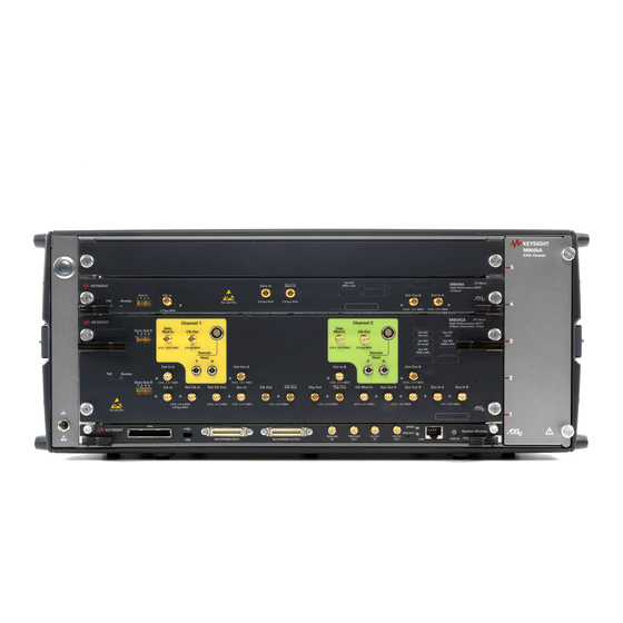
M9505A Axie Chassis
33
Axie Embedded System Module (USB ESM)
34
Host Computer
35
M8030A Overview
36
M9514A Axie Chassis
37
Axie System Module (ASM)
38
Keysight M9537A Axie Embedded Controller Module
39
M8020A / M8030A Modules
40
J-BERT M8041A Generator-Analyzer-Clock Module
40
M8041A Front Panel Connector Inputs/Outputs
43
J-BERT M8051A Generator-Analyzer
45
M8061A 32 Gb/S Multiplexer with De-Emphasis Module
48
M8061A Front Panel Connector Inputs/Outputs
50
M8062A 32Gb/S Front-End for J-BERT M8020A High-Performance BERT
51
M8062A Features
51
M8062A Module Components
52
M8062A Front Panel Pattern Generator Connectors
53
M8062A Front Panel Analyzer Connectors
54
M8020A Module Setup
55
Setting up a Single Channel System
55
Setting up a Multi-Channel System
55
M8030A Module Setup
57
M8030A Modules Arrangement Example
58
M8040A Overview
59
M8040A Modules
60
M8045A High-Performance BERT Pattern Generator-Clock Module
60
M8046A High-Performance BERT Analyzer Module
64
M8057A Pattern Generator Remote Head
66
M8040A Module Setup
69
AWG Modules Supported by M8070A System Software
70
M8195A 65 Gsa/S Arbitrary Waveform Generator
70
M8196A 92 Gsa/S Arbitrary Waveform Generator
71
Other Supported Hardware(S)
72
Keysight N1076A/N1077A DCA-M Clock Recovery
72
Keysight Real Time Oscilloscopes
73
Hardware Setup for M8046A and M8062A Modules
74
Limitations
75
ESD Protection
76
3 Quick Tour with M8070A User Interface
82
Overview
82
Launching M8070A User Interface
83
Messages While Launching M8070A GUI
83
Load Setting
85
Get Module Information
87
Exploring M8070A User Interface
89
Title Bar
89
Menu Bar
89
Main Window
109
Status Bar
110
Other GUI Features
115
Recall/Save Instrument State
122
Recall Instrument State
122
Save Instrument State
123
4 User Interface - M8070A Display Views
125
Overview
126
Module View
127
How to Launch Module View
127
Input and Output Ports
130
Show Module Information
136
Selecting Single/Multiple Ports
137
Parameters Window
137
Creating Groups in the Module View
155
System View
156
Using the Zoom Tool
157
Understanding the System View
158
System View with M8061A Integration
162
System View with M8062A Integration
169
M8040A System View
173
Impairment Setup View
175
How to Access the Impairment Setup View
175
Features of the Impairment Setup View
176
Viewing Options in the Impairment Setup View
178
How to Set Parameters in Impairment Setup View
180
How to Use Filters
182
Group View
185
How to Launch Group View
185
Setup View
191
How to Access the Setup View
191
Understanding Setup View
192
GUI Elements Description
195
How to Perform a Basic Measurement
197
Adjustable Intersymbol Interference
198
Using System View for ISI Configuration
198
How to Launch Adjustable ISI Window
199
Toolbar
200
Adjustable ISI Graph
201
ISI Parameters
201
Intersymbol Interference (ISI) Setup
202
Controlling AWG(S) from M8070A User Interface
203
Awg(S) in Module View
203
M819Xa Configuration
204
Configuring AWG(S) Parameters
207
Simultaneous Injection of CMSI and DMSI Using M819Xa Awgs
209
AWG as External Level Interference (RI/SI) Source
211
System View with AWG(S) Integration
213
Signal Generation in AWG
214
Using AWG Frequency Response Calibration for Improved Signal Performance
215
Selecting Line Coding
215
Creating Patterns for AWG(S)
217
Sequence Settings for AWG(S)
217
Settings to Generate Data and Clock Signals in AWG
219
Jitter Setting in AWG(S)
219
Extended Sequencing Capabilities in Awgs
221
Basic Sequencing
221
Extended Sequencing
221
Block Settings
223
Event Configuration
225
SCPI Commands
225
Controlling N1076A/77A from M8070A
226
One Time Preparation
226
Using N1076A/77A from Within M8070A
228
Flexdca and N1076A/77A Documentation
230
Offline Usage
230
Controlling a Real-Time Oscilloscope from M8070A
233
Required Preparation Steps
234
M8070A
234
Understanding BER Measurement with the Real-Time Oscilloscope
238
Real-Time Oscilloscope in Module View
241
Differences to a Hardware Based Error Detector
242
Best Practices
243
Remote Controlling the Real-Time Oscilloscope Based Error Detector
244
5 Setting up Generator
249
Overview
250
M8020A/M8030A Generator Ports
251
M8040A Generator Ports
253
Understanding the Output Protection Circuit
254
Understanding the Output Level Parameters
255
Why Incorrect Terminations Could Damage Your Device
258
AC Coupling and Bias Tees
258
Setting up Terminations
261
DC Check (Unbalanced/Balanced Termination) for M8040A
262
Adjust Output Levels (Optional)
265
De-Emphasis Signal Generator
266
M8045A De-Emphasis
269
Setting up Data out Port Parameters
272
Setting up Output Timing
274
Line Coding
275
Bit Rate
277
When to Use an External Clock Source
277
Bit Rate Range
277
Spread Spectrum Clocking
279
Setting the Bit Rate
280
External Clock Divider
281
External PLL Clock Divider and Multiplier
281
Trigger Output
282
FEC Error Insertion
284
Error Insertion
288
FEC Error Insertion
290
Interference
294
Common Mode Interference (CMI)
294
Differential Mode Interference (DMI)
295
Jitter Setup
296
High Frequency Jitter (HF Jitter)
296
Low Frequency Jitter (LF Jitter)
296
Global Jitter State On/Off Switch
296
How to Enable Global Jitter State
297
Set Jitter Configuration
297
6 Setting up Analyzer
309
Overview
310
M8020A/M8030A/M8040A Analyzer Ports
311
Data in Port Termination
312
Why Can Wrong Terminations Damage Your Device
312
Setting up Termination
313
Clock Setup
318
How Does Clock Data Recovery Work
318
Phase Locked Loop
318
CDR Setup in M8020A/M8030A
320
CDR Setup for M8040A
321
Sampling Point Setup
323
How Does the Sampling Point Setup Work
323
Auto Alignment
323
Threshold Center Alignment
324
Delay Center Alignment
325
Canceling Auto Align
326
Alignment BER Threshold
326
Sampling Point Setup Window
326
Equalization
332
Equalization in M8041A/M8051A Data in
332
Equalization in M8062A Data in
333
Equalization in M8046A Data in
334
Pattern Synchronization
344
Introduction to Pattern Synchronization
344
What Type of Synchronization Should You Use
347
What Is False Synchronization
348
How Can You Tell if Your Synchronization Is False
349
How to Synchronize an Incoming Pattern
351
Bit Recovery Mode
352
Understanding Bit Recovery Mode (BRM)
352
Setting up Bit Recovery Mode
353
Line Coding
354
Alignment Results
355
7 Setting up Patterns
357
Pattern Overview
358
Sequence Editor
359
Overview
359
When to Use a Sequence
359
How a Sequence Is Defined
359
How to Launch a Sequence Editor
360
Toolbar
361
Creating New Sequence
362
Importing a Sequence
363
Exporting a Sequence
365
Creating a Loop
365
Loop Within Sequences
366
Modifying the Existing Sequences
366
Sequence Setting Window
367
Editing a Pattern in a Sequence Editor
387
Sharing Sequences
388
User-Defined Sequences
389
Sequence Block Display
389
Sequence Block Parameters
389
Select Pattern Dialog
390
Application Specific Patterns
393
Oif Cei
393
Ieee
394
Pattern Editor
395
How to Launch Pattern Editor
395
Toolbar
396
Settings Window
412
Pattern Edit Pane
414
Bit Coding
419
8 B/10B Coding
421
128B/130B Coding
423
128B/132B Coding
425
Pattern Capture
428
How to Launch Pattern Capture Window
428
Toolbar
429
Parameters Window
430
How to Capture a Pattern
431
Pattern Capture Pane
432
Saving a Captured Pattern
433
Capture Results Pane
433
Interactive Link Training
435
PCI Express 3.0/4.0 Testing
435
Link Training Pcie 3.0 and Pcie 4.0 Parameters
440
Link Training for USB 3.0 and USB 3.1
443
Using M8062A Data out Squelch Feature
455
Limitations
455
Hardware Requirements
455
Hardware Setup
455
Software Usage
455
Overview
460
Exploring Measurement User Interface
461
Launching the Measurement User Interface
461
Toolbar
462
Status Indicator
463
Measurement History Window
463
Copy Measurement History Properties
464
Measurement Graph
464
Parameters Window
465
Calculated Results Pane
465
Error Ratio Measurement
467
Overview
467
Launching Error Ratio Measurement
467
Acquisition and Evaluation Parameters for Error Ratio
469
How to Run a Measurement
470
Error Ratio Measurement with PAM4 Symbols
471
How to Stop a Measurement
472
Measurement Graph
472
Test Times and Confidence Levels
473
Calculated Results
474
Error Ratio Measurement for a Group of Analyzers
477
Output Timing Measurement
479
Output Timing Characteristics
479
Jitter Characteristics
479
Example Results
479
Understanding the Jitter Calculation
480
Explanation of the Fast Total Jitter Measurement
483
Evaluation Parameters
485
Launching the Output Timing Measurement
487
Parameters Pane
488
How to Run Output Timing Measurement
489
How to Stop Output Timing Measurement
489
Measurement Graph
490
How an Output Timing Measurement Works
490
Calculated Results
491
Fast Total Jitter Measurement Results
493
Calculated Results for Fast Total Measurement
493
Output Level Measurement
495
Overview
495
Launching the Output Level Measurement
495
Parameters Window
496
Changing the Measurement Setting
499
Available Views
499
How to Execute Output Level Measurement
500
How to Stop Output Level Measurement
500
Measurement Graph
500
How to Improve the Output Levels Display
502
How to Change the Output Levels Properties
502
Calculated Results
503
Jitter Tolerance Measurement
508
Overview
508
Understanding Jitter Tolerance
508
Types of Jitter
510
BER Setup
511
Graph Setup
511
Instrument Setup
512
Measurement Setup
512
Launching Jitter Tolerance Measurement
518
How to Run Jitter Tolerance Measurement
519
How to Stop/Abort Jitter Tolerance Measurement
519
Measurement Graph
520
Viewing the Jitter Tolerance Results
521
Saving Jitter Tolerance Measurement Results
522
Using the Jitter Tolerance Template Editor
522
Template Editor Toolbar
523
Template Editor Functions
524
Eye Diagram Measurement
525
What Is an Eye Diagram
525
Methods of Representation of Eye Diagram
526
Eye Diagram Measurement Parameters
528
Launching the Eye Diagram Measurement
530
How to Start/Abort an Eye Diagram Measurement
530
How to Change the Default Settings
531
Calculated Eye Diagram Results
532
Parameter Sweep Plugin
534
Launching Parameter Sweep Plugin
534
Parameter Sweep Plugin Parameters
535
How to Run Parameter Sweep Measurement
537
How to Stop Parameter Sweep Measurement
537
Measurement Graph for Parameter Sweep
537
Measurement Data for Parameter Sweep
539
9 Utilities
541
Overview
542
Script Editor
543
Launching the Script Editor
544
Toolbar
545
Editor Pane
547
Output Pane
548
Console
549
Settings Window
549
Find and Replace
551
Creating a Script
552
Saving a Script
552
Importing a Script
552
Exporting a Script
553
Running a Script
553
Stopping a Script
554
Adding Duplicate Row/Selection in the Code
554
DUT Control Interface
556
Launching the DUT Control Interfacer
556
Toolbar
558
Editor Pane
560
Output Pane
562
Console
562
Insert Code Window
563
Settings Window
563
Find and Replace
565
Creating a New Script
566
Open a Script
566
Saving a Script
566
Importing a Script
566
Exporting a Script
567
Running a Script
568
Stopping a Script
568
Adding Duplicate Row/Selection in the Code
568
Effects on M8070A GUI on Installing a DUT Control Script
569
Writing a Script Code for DUT Control Interface
571
Communication with the M8070A Instrument Layer
578
SCPI Editor
588
SCPI Basics
588
Executing SCPI Commands
592
SCPI Recorder
593
Self Test Utility
596
Launching the Self Test Utility
596
Toolbar
597
Self Test History
597
Self Test Results Window
598
Executing Self Test
598
Aborting Self Test
599
Saving Self Test Results
599
Deleting Self Test Results
600
Licenses Window
601
Launching the Licenses Window
601
Settings Window
602
Display Tab
603
Channel Tab
603
Hints Tab
604
Logger Window
605
SCPI Server Information
606
Plug-In Manager
607
How to Launch Plug-In Manager
607
How to Install a Plug-In
608
How to Uninstall a Plug-In
609
How to Update a Plug-In
610
How to Access an Installed Plug-In through M8070A User Interface
612
10 Licenses
614
Overview
614
Supported Licenses
615
Node-Locked (Uncounted) Licenses
615
Floating Licenses
617
Module-Specific Licenses
617
M8020A/M8030A Licenses
618
M8070A System Software for M8000 Series of BER Test Solutions
618
M8041A - High-Performance BERT Module
618
Module
620
M8051A - High-Performance BERT Module
622
Module
623
M8061A Multiplexer 2:1 with De-Emphasis
624
M8062A 32Gb/S Front-End for J-BERT M8020A High-Performance BERT
624
M8040A Licenses
626
M8045A Pattern Generator and Clock Module, 32/64 Gbaud
626
M8046A Analyzer Module, 32/64 Gbaud
627
Keysight License Manager
628
Keysight License Service
629
Installing the Licenses
630
Software Requirements
630
Installing M8070A-OTP License (Not Required for M8020A-BU1 and M8030A-BU1)
630
Installing Temporary License (Trial License) for the M8000 Series
630
Installing M8070A-ONP Floating/Networked License
631
Installing the Flexnet License Manager
633
Creating a New License Service Using Lmadmin.exe
642
Installing and Setting up Client PC Floating Licenses
643
Installing Module Licenses (Not Required for M8020A-BU1 and M8030A-BU1)
644
Transporting an M8070A License
645
11 Appendix
647
Basic Troubleshooting
648
Updating Software Components
648
The Chassis Does Not Power up
648
Module Is Exceptionally Hot
648
Contacting Keysight Technologies
648
M8070A Factory Patterns
649
Advertisement
Keysight Technologies M8000 Series Installation Manual (78 pages)
BER Test Solutions.
Brand:
Keysight Technologies
| Category:
Control Unit
| Size: 15 MB
Table of Contents
Safety Summary
3
Compliance and Environmental Information
6
About this Guide
7
Table of Contents
9
Hardware and Software Requirements
14
Hardware Configurations for M8020A
15
M8020A Base System Configuration
15
M8020A Four Channel System Configuration
16
M8020A 32 Gb/S BERT Configuration (Pattern Generator Only)
17
M8062A 32Gb/S Front-End for J-BERT M8020A High-Performance BERT
18
Single M8020A LAN Network Configuration
19
Hardware Configurations for M8030A
20
Hardware Configurations for M8040A
22
M8045A Pattern Generator Module
22
M8046A Analyzer Module
23
M8057A/B Remote Head
23
M8040A LAN Network Configuration
24
2 Installing Modules
25
Axie Instrument Modules
26
Installing M8020A Module(S)
27
To Install the M8041A Module
28
To Install the M8041A and M8051A Modules
30
To Install the M8041A and M8061A Modules
33
To Install the M8041A and M8062A Modules
35
To Remove an M8020A Module
37
Setting up the M8020A
39
Benchtop Configuration
39
Benchtop Configuration with Support Assembly
40
Rack Mounted Configuration
40
Installing the Axie Embedded Controller Module
41
Setting up the M8030A
43
Removing Filler Panels
46
Installing the Axie Embedded Controller Module
46
Installing a Module
49
Removing a Module
52
Synchronization Cable Configuration
52
Installing M8040A Module(S)
55
To Install the M8045A Module
56
To Install the M8045A and M8046A Modules
58
To Connect the M8057A/B Remote Head
60
To Remove an M8040A Module
61
Setting up the M8040A
63
Benchtop Configuration
63
Rack Mounted Configuration
63
Installing the Axie Embedded Controller Module
64
Completing the Installation and Setup Process
66
3 Controlling Multiple Instruments
67
Controlling Multiple Instruments by Multiple Instances of M8070B System Software
70
Remote Control of Multiple M8070B Software Instances
74
Command Line Options
74
Creating M8070B Software Shortcut on the Desktop
75
Index
77
Keysight Technologies M8000 Series Getting Started Manual (72 pages)
BER Test Solutions, High-Performance BERT
Brand:
Keysight Technologies
| Category:
Test Equipment
| Size: 4 MB
Table of Contents
Safety Summary
3
Compliance and Environmental Information
6
About this Guide
7
Table of Contents
9
1 Introduction
13
Introduction
14
Key Features
14
Applications
14
M8040A Modules
16
M9505A Axie Chassis
17
Axie Embedded System Module (USB ESM)
18
Keysight M9537A Axie Embedded Controller Module
19
Host Computer
20
M8045A High-Performance BERT Pattern Generator-Clock Module
21
M8045A Features
21
M8045A Module Components
21
M8045A Front Panel Input/Output Ports
23
M8046A High-Performance BERT Analyzer Module
25
M8046A Features
25
M8046A Module Components
25
M8046A Front Panel Inputs/Outputs Ports
26
M8057A Pattern Generator Remote Head
28
M8057A Remote Head Components
28
2 Basic Setup for M8040A
31
Step 1 - Unpack the Shipment
32
Repair/Replacement
33
Step 2 - Set up the M8040A
33
Step 3 - Set up the External Host Computer (Not Required for M8040A-BU1)
33
Computer Hardware and Software Requirements
34
To Connect Via USB
35
To Connect Via Pcie
35
Step 4 - Connect the M9505A Axie Chassis to a Power Supply
36
Step 5 - Power up (if Connecting Via Pcie)
37
Step 6 - Verify Basic M8040A Operation
38
Step 7 - Install Keysight IO Libraries Suite (Not Required for M8040A-BU1)
39
Step 8 - Install M8070A Software (Not Required for M8040A-BU1)
39
Step 9 - Install the Licenses
40
Installing M8070A-0TP License (Not Required for M8040A-BU1)
41
Installing Temporary License (Trial License) for the M8000 Series
41
Installing M8070A-0NP Floating/Networked License
42
Installing the Flexnet License Manager
43
Installing Module Licenses (for Upgrades Only)
49
Transporting an M8070A License
50
Affix Option Label (Optional)
50
Step 10 - Turning off the Chassis and Modules
52
Step 11 - Connect the M8040A to the Device under Test (DUT)
52
Typical Test Setup Example
52
M9537A Embedded Controller Setup Example
53
Hardware Connections
54
3 Using the M8040A High-Performance BERT
55
Locating Electronic Manuals and Online Help
56
Routine Care
56
Starting the M8070A Software
57
Perform a Measurement
58
Updating Software Components
66
Contacting Keysight Service and Support
66
Quick Troubleshooting
66
Index
69
Advertisement
Keysight Technologies M8000 Series Manual (32 pages)
BER Test Solutions
Brand:
Keysight Technologies
| Category:
Control Unit
| Size: 1 MB
Table of Contents
Warranty
2
Keysight Cybersecurity
3
Safety Summary
4
Safety Symbols
5
Compliance and Environmental Information
7
Table of Contents
9
Tools Shipped with M8000 Series Modules
11
Preventing Damage to M8050A Connectors Including M8042A/M8043A/M8067A Connectors
12
Tips for Connecting and Removing M8050A Connectors
12
Tips for Connecting and Removing M8042A Connectors (External Semi-Rigid Cable Connection)
15
Tips for Connecting and Removing Cables To/From M8053A Interference Source
20
Connecting the Adapter to the Cable M8053A-801
20
Mounting the Cable with Attached Adapter to the M8053A Front Panel
21
General Tips to Prevent Unnecessary Repairs
22
Use Proper Connector Care and Connection Techniques
22
Protect the Input and Output Connectors
23
Protect the RF Connectors
23
Follow Proper RF Cable and Connector Care
24
Making a Connection
24
Using the Torque Wrench
25
Final Connection Using a Torque Wrench
26
Ensure Proper Grounding
26
Read the Warning Labels and Specifications
27
Avoid Overpowering the Product
27
Ensure Proper Instrument Cooling (Airflow)
27
Follow Electrostatic Discharge Precautions
28
Use Cable Discharger Box to Discharge Cables
28
Use Proper Lifting Techniques
30
Use Proper Packaging for Transport
30
Check Your Instrument Settings
30
Get more Information
30
Get the Latest Information about Your Product
31
Advertisement
Related Products
Keysight Technologies M8040A-BU1
Keysight Technologies M8040A-BU2
Keysight Technologies M8030A Multi-Channel BERT
Keysight Technologies M8040A High-Performance BERT
Keysight Technologies M8085A
Keysight Technologies MSO9064A
Keysight Technologies M9703A
Keysight Technologies M9362A-D01 PXIe
Keysight Technologies Infiniium MXR608A
Keysight Technologies Infiniium MXR108A
Keysight Technologies Categories
Measuring Instruments
Test Equipment
Control Unit
Portable Generator
Power Supply
More Keysight Technologies Manuals
Login
Sign In
OR
Sign in with Facebook
Sign in with Google
Upload manual
Upload from disk
Upload from URL