Table of Contents
Advertisement
Quick Links
PCE Americas Inc.
PCE Instruments UK Ltd.
711 Commerce Way
Unit 11
Suite 8
Southpoint Business Park
Jupiter
Ensign way
FL-33458
Hampshire / Southampton
USA
United Kingdom, SO31 4RF
From outside US: +1
From outside UK: +44
Tel: (561) 320-9162
Tel: (0) 2380 98703 0
Fax: (561) 320-9176
Fax: (0) 2380 98703 9
info@pce-americas.com
info@industrial-needs.com
www.pce-instruments.com/english
www.pce-instruments.com
Grain Moisture Analyzer
PCE-A-315
INSTRUCTION MANUAL
Advertisement
Table of Contents

Related Manuals for PCE Health and Fitness PCE-A-315


Summary of Contents for PCE Health and Fitness PCE-A-315
- Page 1 Hampshire / Southampton United Kingdom, SO31 4RF From outside US: +1 From outside UK: +44 Tel: (561) 320-9162 Tel: (0) 2380 98703 0 Fax: (561) 320-9176 Fax: (0) 2380 98703 9 info@pce-americas.com info@industrial-needs.com www.pce-instruments.com/english www.pce-instruments.com Grain Moisture Analyzer PCE-A-315 INSTRUCTION MANUAL...
-
Page 2: Table Of Contents
Contents Contents GENERAL SAFETY RECOMMENDATIONS .............. 3 1. GENERAL INFORMATION ..................4 2. SPECIFICATIONS....................6 3. PRINCIPLE OF OPERATION ................. 7 4. WORKING WITH CONTROL PANEL..............8 4.1. C ....................8 ONNECTIONS 4.2. S ..... 10 ELECTING PRODUCT AND PERFORMING MOISTURE MEASUREMENTS 4.3. -
Page 3: General Safety Recommendations
General safety recommendations General safety recommendations The product is designed for industrial use. Installation and service must be carried only out by trained and authorized personnel and according to valid standards. Before making any electrical connections, ensure that power supply voltage and frequency meet the specifications provided on the labels of devices and in this manual. -
Page 4: General Information
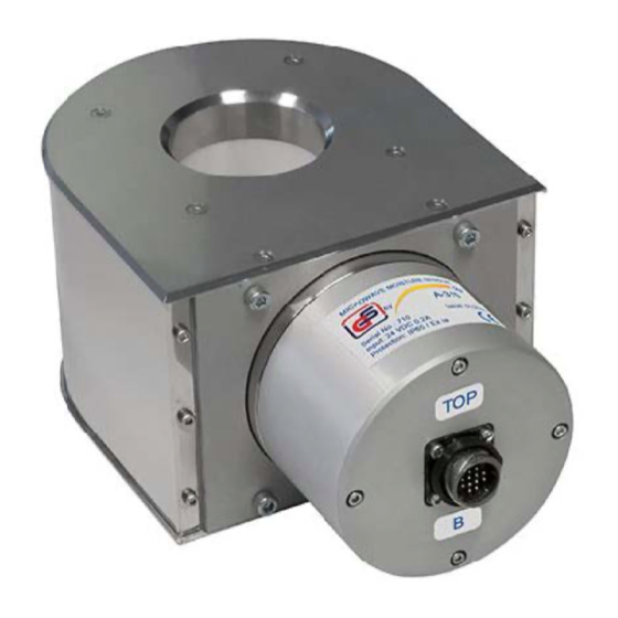
General information 1. General information The system of online moisture content measurement is designed for continuous measurement of current moisture content of grain products, oil or leguminous crops and other products at inlet and outlet of continuous flow grain dryers. fig 1. - Page 5 General information Control panel allows adjusting scaling settings of two moisture content current loop outputs for use in automation systems, storing correction coefficients for meas- ured moisture content of every product, time-averaging of measurement results and other functions described in this manual. 5/29...
-
Page 6: Specifications
Specifications 2. Specifications Sensor type ..............microwave; Measuring mode ............continuous; Measuring range ............5 – 40%; Moisture content measurement error (up to 18%) ..±0.5% max; Moisture content measurement error (18-40%) ... ±1% max; ... -
Page 7: Principle Of Operation
Principle of operation 3. Principle of operation The principle of sensor A315 operation is based on the considerable difference of the permittivity of dry substances and water at ultra-high frequencies (UHF). The feature and important advantage of A315 moisture content sensor is that due to simultaneous measurement of resonant frequency and amplitude of the reso- nance and special processing algorithm, moisture content measurements become practically independent of product bulk density. -
Page 8: Working With Control Panel
Working with control panel 4. Working with control panel 4.1. Connections Control unit is designed to work with two A315 grain moisture content sensors. One of the sensors has address A, and the second one – address B. fig 3. Wiring diagram Control panel is supplied with two pre-wired cables (3 m each) for connecting the sensors. - Page 9 Working with control panel fig 4. Control panel screen after system startup 9/29...
-
Page 10: Selecting Product And Performing Moisture Measurements
Working with control panel 4.2. Selecting product and performing moisture measurements The work with moisture content sensors starts with product selection. Press to open product selection menu (fig. 5). fig 5. Product selection menu Select the product and confirm selection by pressing . - Page 11 Working with control panel When grain is removed from moisture meters, the current values of the moisture will show zero, but the average values will retain their previous readings (fig. 7). Av- eraged values can be reset by pressing on them when the measurement channel of the sensor is empty.
- Page 12 Working with control panel display average of moisture content of the product based on four sample measure- ments. After this the similar procedure can be performed for sensor B (fig. 9). fig 9. Product moisture measured in “Laboratory” mode In certain cases the number of measurements in mode should be increased for correct measurements.
-
Page 13: Trend View
Working with control panel 4.3. Trend view Control panel provide an option to display trends of measured grain temperature and moisture content for the time period since the sensor start up. Press button to view trends. The screen will display the last 10 minutes trend of moisture content for sensor A (fig. - Page 14 Working with control panel the sensors at a particular moment of time click on a trend section corresponding to this moment and read the value in the "Watch line" line at the bottom of the screen (fig. 12). The scale of vertical axis can be changed. To change the upper limit press on the limit value and enter a new value using numeric keypad.
-
Page 15: Entering Corrections And Parameters
Working with control panel 4.4. Entering corrections and parameters The system of online moisture control allows adjusting scaling parameers of cur- rent loop outputs and applying individual correction and averaging coefficients for each sensor. Press button to enter “Settings” menu. The display will show pass- word enter screen. - Page 16 Working with control panel of the screen. The selected sensor is indicated by the corresponding letter in the left top corner of the panel (fig. 16). fig 16. Selecting sensor А Press button to read parameters from sensor A (fig. 17). To select mode for current loop output press button confirm selection by pressing .
- Page 17 Working with control panel “for minimum current” line. Enter new value and press (fig. 18). Press in the “Current output settings” to apply and check new settings. The moisture content value corresponding to the minimum current can be changed in similar way. fig 18.
- Page 18 Working with control panel “1 Offset - 0.0%” and enter “0.5%” confirming input by pressing . After this the “Moisture” line should read 13.8% (fig. 19). fig 20. Algorithm 2 Algorithm 2 uses Bulk Density Coefficient (BDC) (fig. 20). Sensor A315 is cali- brated for different products with bulk densities (test weight) as per Table 1.
- Page 19 Working with control panel When it is possible to determine bulk density of the custom product then correc- tion coefficient “2 BDC” may be tuned for better measurement accuracy. For exam- ple, the measured bulk density of corn passing through sensor is 0.810 kg/l. Accord- ing to Table 1, bulk density of corn for which the moisture sensor was calibrated is 0.726 kg/l.
- Page 20 Working with control panel urement and press button on the screen. Calibration screen will appear (fig. 22). fig 22. Calibration Press and after the calibration the screen should show “– Moisture 0.0%” (fig. 23). Calibration is finished and the sensor is ready for measurements. fig 23.
- Page 21 Working with control panel target and line will turn red and start flashing (fig. 25). Sound alarm can be disabled by pressing button. fig 24. «System» screen fig 25. Moisture level alarm Sliding window averaging may be used for averaging of moisture content measurement results.
- Page 22 Working with control panel fig 26. Turning off sensors Selection of sensor А or В can be performed not only in mode but in mode (fig. 4) as well. Pressing the letter corresponding to the sensor ad- dress in mode will turn the sensor off (fig. 26). Moisture and temperature values will read zero.
-
Page 23: Viewing Archive Data
Working with control panel 4.5. Viewing archive data Control panel stores data archive for the whole period of grain dryer operation. To view the archive, press button, and the panel will display image of mois- ture content trend over the past day (fig. 27). fig 27. -
Page 24: Setting Time And Date
Working with control panel 4.6. Setting time and date To set time and date press button in the bottom right corner of the display. In the appeared menu press button. Password window and keyboard will appear (fig. 28). Input “111111” (six times “one”) as the password. Press “Time/Date” button to enter time and date settings mode and set correct time and date with buttons . -
Page 25: Installation
Installation 5. Installation For correct operation and measurement complete filling of sensor’s measuring channel with grain must be ensured. Depending on the design of grain dryer sensors can be installed different ways. Several methods are described in this manual. To control flow moisture content of at the inlet the sensor should be installed on the side wall of bunker in its upper part where the bunker is filled. - Page 26 Installation (green light glows on the panel) and is ready for measuring moisture content of a new portion of grain. fig 30. Installation in the output bunker Not all grain dryer allow installing A315 sensors in the described manner. In case grain is unloaded from the bunker in small portions, the most accurate meas- urements can be demonstrated when using small flexible spiral screw conveyor mounted below moisture sensor (fig.
-
Page 27: Troubleshooting
Troubleshooting 6. Troubleshooting Problem: «Communication error» message on the screen (fig. 32). Solution: check the integrity of communication cables from moisture sensors to the control panel and reliability of connecting leads. fig 32. “Communication error” message Problem: «Error 7» message on the screen (fig. 33). Solution: repeat selection of product in mode. - Page 28 Troubleshooting In case of other failures please contact the manufacturer representatives or lo- cal dealer. After the end of drying season it is recommended to dismount moisture sensors from the grain dryer and store them in dry heated space. Moisture sensor connectors shall be protected from direct water effect.
-
Page 29: Dimensional Drawing
Dimensional drawing 7. Dimensional drawing 29/29...
Need help?
Do you have a question about the PCE-A-315 and is the answer not in the manual?
Questions and answers