Table of Contents
Advertisement
Quick Links
Condition Monitoring
Model : PCE-T 238
OPERATION MANUAL
PCE Americas Inc.
711 Commerce Way
Suite 8
Jupiter
FL-33458
USA
From outside US: +1
Tel: (561) 320-9162
Fax: (561) 320-9176
info@pce-americas.com
Your purchase of this
PHOTO/CONTACT
TACHOMETER marks a
step forward for you into
the field of precision
measurement. Although
this TACHOMETER is a
complex and delicate
instrument, its durable
structure will allow many
years of use if proper
operating techniques are
developed. Please read
the following instructions
carefully and always keep
this manual within easy
reach.
PCE Instruments UK Ltd.
Southpoint Business Park
Hampshire / Southampton
United Kingdom, SO31 4RF
From outside UK: +44
Tel: (0) 2380 98703 0
Fax: (0) 2380 98703 9
info@industrial-needs.com
www.pce-instruments.com/english
www.pce-instruments.com
Unit 11
Ensign way
Advertisement
Table of Contents

Subscribe to Our Youtube Channel
Related Manuals for PCE Health and Fitness PCE-T 238


Summary of Contents for PCE Health and Fitness PCE-T 238
- Page 1 Tel: (561) 320-9162 Tel: (0) 2380 98703 0 Fax: (561) 320-9176 Fax: (0) 2380 98703 9 info@pce-americas.com info@industrial-needs.com www.pce-instruments.com/english Model : PCE-T 238 www.pce-instruments.com Your purchase of this PHOTO/CONTACT TACHOMETER marks a step forward for you into the field of precision measurement.
-
Page 2: Table Of Contents
TABLE OF CONTENTS 1 FEATURES................2 SPECIFICATIONS..............3 FRONT PANEL DESCRIPTION......... 3-1 Display................3-2 TEST(Power) Button............3-3 Function Button............3-4 Memory Button............4 3-5 Surface Speed Wheel..........4 3-6 RPM Adapter ( Contact Tach. )............. 3-7 Photo Tach. detect sensor..............3-8 Laser Light Beam............ -
Page 3: Features
1. FEATURES * Compact and pocket tachometer. * The best Tachometer in the world. 2 in 1, one instrument combine Photo tachometer and Contact Tachometer. * Photo tachometer uses Laser light detecting source, long measuring range up to 1.5 meters, it is useful in the RPM measurement application where the machine would be a risk to the operator or close access is difficult or not possible. -
Page 4: Specifications
2. SPECIFICATIONS Measurement Photo Tachometer : & Range 5 to 99,999 RPM. Contact Tachometer : 0.5 to 19,999 RPM. Surface Speed : m/min. - 0.05 to 1,999 m/min. ft/min. - 0.2 to 6,560 ft/min. in/min. - 2.0 to 78,740 in/min. Resolution 0.1 RPM ( <... - Page 5 165 x 50 x 33 mm. ( 6.5 x 2.0 x 1.3 inch ). Weight 149 g ( 0.33 LB ). * W/O batteries. Accessories Tachometer PCE-T 238....1 PC. Rubberized measuring tip Included (cone shape)........ 2 PC. Rubberized measuring tip ....
-
Page 6: Front Panel Description
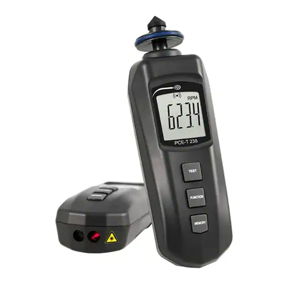
3. FRONT PANEL DESCRIPTION Fig. 1 3-1 Display 3-2 TEST(Power) Button 3-3 Function Button 3-4 Memory Button 3-5 Surface Speed Wheel 3-6 RPM Adapter ( Contact Tach. ) 3-7 Photo Tach. detect sensor 3-8 Laser Light Beam 3-9 Battery Cover/Compartment 3-10 Reflecting Mark 3-11 Monitor indicator 3-12 RS-232 Output Terminal... -
Page 7: Measuring Procedures
4. MEASURING PROCEDURE 4-1 Change the function 1) Short press the " TEST(Power) Button " ( 3-2, Fig. 1 ) once, the meter will power ON, 2) Short Press " Function Button " ( 3-3, Fig. 1 ) momentarily in sequence, the function will change to a. -
Page 8: Photo Rpm Measurement
4-2 Photo RPM measurement 1) Select ( default ) the function to " Photo RPM ", refer chapter 4-1, page 5. 2) Align the " Laser Light Beam " ( 3-8, Fig. 1 ) with the applied target. Verify that the " Monitor Indicator "... -
Page 9: Surface Speed Measurement
4-4 Surface Speed Measurement 1) Select ( default ) the function to surface speed " m/min " " ft/min " or " in/min " refer chapter 4-1, page 5. 2) Simply attaching the " Surface Speed Wheel " ( 3-5, Fig. 1 ) to the detector.reading stabilizes ( approx. -
Page 10: Battery Replacement
6. BATTERY REPLACEMENT * Replace the batteries when the LCD displays the low battery icon " ", using 4 fresh 1.5 V ( UM4, AAA ) batteries. * To change the batteries, open the " Battery Cover " ( 3-9, Fig. 1 ). * Make sure the "... - Page 11 Meter (9W 'D" Connector) (3.5 mm jack plug) Center Pin........... Pin 4 Ground/shield........... Pin 2 2.2 K resister Pin 5 The 16 digits data stream will be displayed in the following format : D15 D14 D13 D12 D11 D10 D9 D8 D7 D6 D5 D4 D3 D2 D1 D0 Each digit indicates the following status : Start Word = 02 D12 &...
- Page 12 RS232 setting Baud rate 9600 Parity No parity Data bit no. 8 Data bits Stop bit 1 Stop bit...
Need help?
Do you have a question about the PCE-T 238 and is the answer not in the manual?
Questions and answers