Table of Contents
Advertisement
Quick Links
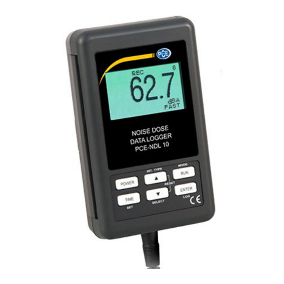
Sound Level Meter
PCE-NDL 10
OPERATION MANUAL
SD card real time datalogger, RS232/USB
Frequency weighting and Time weighting
meet IEC 61672 class 2 ,
Personal sound exposure meet IEC 61252
PCE Americas Inc.
711 Commerce Way
Suite 8
Jupiter
FL-33458
USA
From outside US: +1
Tel: (561) 320-9162
Fax: (561) 320-9176
info@pce-americas.com
www.pce-instruments.com/english
www.pce-instruments.com
Your purchase of this
Personal sound exposure
Noise Dosimeter
with SD CARD
DATALOGGER marks a
step forward for you
into the field of
precision measurement.
Although this METER is
a complex and delicate
instrument, its durable
structure will allow
many years of use if
proper operating
techniques are
developed. Please read
the following
instructions carefully
and always keep this
manual within easy
reach.
PCE Instruments UK Ltd.
Units 12/13
Southpoint Business Park
Ensign way
Hampshire / Southampton
United Kingdom, SO31 4RF
From outside UK: +44
Tel: (0) 2380 98703 0
Fax: (0) 2380 98703 9
info@industrial-needs.com
Advertisement
Table of Contents

Related Manuals for PCE Health and Fitness PCE-NDL 10


Summary of Contents for PCE Health and Fitness PCE-NDL 10
-
Page 1: Sound Level Meter
Fax: (561) 320-9176 Fax: (0) 2380 98703 9 info@pce-americas.com info@industrial-needs.com www.pce-instruments.com/english Sound Level Meter www.pce-instruments.com PCE-NDL 10 Your purchase of this Personal sound exposure Noise Dosimeter with SD CARD DATALOGGER marks a step forward for you into the field of precision measurement. -
Page 2: Table Of Contents
TABLE OF CONTENTS 1. FEATURES....................... 2. SPECIFICATIONS....................3. FRONT PANEL DESCRIPTION................4. MEASURING PROCEDURE..................4-1 Sound Pressure Level Measurements (SPL)......... 7 4-2 Running the Dose Meter Noise Survey (DOSE %)………………….. 4-3 Data Hold......................4-4 Data Record ( Max., Min. reading )................4-5 LCD Backlight ON/OFF…………………………………………………………………... -
Page 3: Features
1. FEATURES * Personal sound exposure meet IEC 61252 * Frequency and Time weighting are designed to meet IEC 61672 class 2. * A & C weighting networks comply with standards. * LCD is dot-matrix with backlight and easy reading. * Combination Dose meter, Data-logger and Sound level meter. -
Page 4: Specifications
2. SPECIFICATIONS Circuit Custom one-chip of microprocessor LSI circuit. Display LCD size : 50 mm x 30 mm LCD with green backlight ( ON/OFF ). Measurement SPL : Sound pressure level Type Dose t est noise exprosure : : : : Measurement A uto 30 - 130 dB. - Page 5 Frequency Characteristics of A & C. Weighting Network A weighting : The characteristic is simulated as "Human Ear Listing" response. Typical, if making the environmental sound level measurement, always select to A weighting. C weighting The characteristic is near the "FLAT" response.
- Page 6 Calibration VR Build in external calibration VR, easy to calibrate on 94 dB level by screw driver. * Calibrated via external SOUND CALIBRATOR ( SC-942, optional ). Calibrator B & K (Bruel & kjaer), MULTIFUNCTION ACOUSTIC CALIBRATOR Type 4226. Datalogger Auto 1 second to 3600 seconds Sampling Time...
- Page 7 Power off Auto shut off saves battery life or manual off by push button. Operating 0 to 50 ℃ Temperature Operating Less than 85% R.H. Humidity Power Supply * AC/DC power adapter is optional. Alkaline or heavy duty DC 1.5 V battery ( UM4, AAA ) x 6 PCs, or equivalent.
-
Page 8: Front Panel Description
3. FRONT PANEL DESCRIPTION Fig. 1 3-1 Display. 3-11 Microphone input jack 3-2 Power Button( Backlight Button ) 3-12 External 94dB CAL. VR Button Hold only for SPL 3-13 Reset Switch. ▲ 3-4 RUN Button ( REC only for SPL) 3-14 RS232 Output 3-5 TIME Button (Set) 3-15 SD card socket... -
Page 9: Measuring Procedure
4. MEASURING PROCEDURE 4-1 Sound Pressure Measurements (SPL) In SPL mode the display shows readings of the sound pressure level. 1) Power ON the meter by pressing and holding the " Power Button " ( 3-2, Fig. 1 )for at least 1.5 seconds, the meter's default function is "... -
Page 10: Running The Dose Meter Noise Survey (Dose %)
4-2 Running the Dose Meter Noise Survey 1) In " SPL" mode to select the " Dose " mode by pressing and holding the" RUN button" ( 3-4 Fig 1 ) into the DOSE mode . 2) In "DOSE" mode, display will show DUR(duration) , 0.00(cumulative dose) , 00 : 00 :00(current time) , 0(record sampling time counter) , %DOSE(Dose mode) , FAST(Time weighting). -
Page 11: Data Hold
pressing and holding the button , display is shown ▲ and the BEG , x.xx , xx - xx : xx(date - hr : min) and then pressing and holding the button , display is shown ▼ and the BEG , xx - xx : xx(dd - h : m) and END xx - xx : xx(dd - h : m) , pressing button to set ▲... -
Page 12: Lcd Backlight On/Off
2) With the " REC " symbol on the display : a) Press the " RUN Button " ( 3-4, Fig. 1 ) once, the " REC MAX " symbol along with the maximum value will appear on the display. Press the " RUN Button" again the "... -
Page 13: Datalogger
5. DATALOGGER 5-1 Preparation before execute datalogger function The dose meter measured data first be stored into the meter internal built EEPROM, can be stored total of 16,000 sets of data, when stored > 16000 sets , datalogger will be stop and display will show FULL. Remark : How to send the storage of information, you have two choices. - Page 14 Remark : How to set the sampling time, refer to Chapter 7-2, page 18. In Dose mode please start datalogger , then run Dose Function. b. Pause the datalogger During execute the Datalogger function , if press the " ENTER Button " ( 3-7, Fig. 1 ) once will pause the Datalogger function ( stop to save the measuring data into the memory circuit temporality ).
-
Page 15: Manual Datalogger ( Set Sampling Time = 0 Second )
please refer chapter 7-6 ( page 20 ). * It recommend strongly, do not use memory cards that have been formatted by other meter or by other installation ( such as camera…) Reformat the memory card with your meter. * If the sd memory card exist the trouble during format by the meter , use the Computer to reformat again can fix the problem . -
Page 16: Check Time And Sampling Time Information
5-4 Check time and sampling time information During the measurement if press " TIME Button " ( 3-5, Fig. 1 ) ones, the LCD display will present the time and sampling time information of Year/Month/ Date , Hour/ Minute/Second, and sampling time informationin in second unit. -
Page 17: Saving Data From The Sd Card To The Computer
6. Saving data from the SD card to the computer ( EXCEL software ) 1) After execute the Data Logger function, take away the SD card out from the " SD card socket " ( 3-15, Fig. 1 ). 2) Plug in the SD card into the Computer's SD card slot ( if your computer build in this installation ) or insert the SD card into the "... - Page 18 EXCEL graphic screen ( for example )
-
Page 19: Advanced Setting
7. ADVANCED SETTING Under do not execute the Datalogger function, press the " TIME Button " ( 3-5, Fig. 1 ) continuously at least 1.5 seconds will enter the " Advanced Setting " mode. then press the "TIME Button " (3-5, Fig. 1 ) once a while in sequence to select the eleven main function, the lower display will show : DATE……... -
Page 20: Set Sampling Time
2) After set all the time value ( Year, Month, Date, Hour, Minute, Second ), the screen will jump to " Set sampling time character " setting screen ( Chapter 7-2 ). Remark : After the time value is setting, the internal clock will run precisely even Power is off ( The battery is under normal condition, no low battery condition ). -
Page 21: Set Beeper Sound On/Off
7-4 Set beeper sound ON/OFF When the lower display show " BEEP " 1) Use the " Button " ( 3-3, Fig. 1 ) or " Button " ▲ ▼ ( 3-6, Fig. 1 ) to select the upper text to " YES " or "... -
Page 22: Sd Memory Card Format
2) After select the upper text to " USA " or " EURO ", press the " ENTER Button " ( 3-7, Fig. 1 ) will save the setting function with default. 7-6 SD memory card Format When the lower display show " SD-F " 1) Use the "... -
Page 23: Power Supply From Dc Adapter
Note : a. The characteristic table of A, C weighting, please ref. page 24. b. The characteristic of A weighting is simulated as the " Human Ear Listening " response. Typically always select the A weighting when makes environmental sound level measurement. c. -
Page 24: Battery Replacement
10. BATTERY REPLACEMENT 1) When the left corner of LCD display show " ", it is necessary to replace the battery. However, in-spec. measurement may still be made for several hours after low battery indicator appears before the instrument become inaccurate. 2) Loose the "... - Page 25 The 16 digits data stream will be displayed in the following format : D15 D14 D13 D12 D11 D10 D9 D8 D7 D6 D5 D4 D3 D2 D1 D0 Each digit indicates the following status : Start Word When send the SPL display data = 1 When send the DOSE display data = 2 D12, D11 Annunciator for Display...
-
Page 26: Frequency Weighting Characteristics Calibration
12. CALIBRATION 1) Prepare the optional " SOUND CALIBRATOR ", such as " SC-941 " or " SC-942 " ( set range to 94.0 dB ). Power on the Sound Calibrator & plug calibrator output socket into the " Microphone " head ( 3-8, Fig. 1 ) of the Sound Level meter. -
Page 27: Time Weighting (Fast & Slow)
14. TIME WEIGHTING ( F/S ) CHARACTERISTICS Max. response Tolerance Charac. ref. continuous ( IEC 61672 Class 2 ) signal F ( Fast ) - 1.0 dB + 1.0 dB , - 2.0 dB S ( Slow ) - 4.1 dB ±2.0 dB * Test under signal on 1,000 Hz/94 dB.
Need help?
Do you have a question about the PCE-NDL 10 and is the answer not in the manual?
Questions and answers