Table of Contents
Advertisement
Quick Links
POWER
ANALYZER
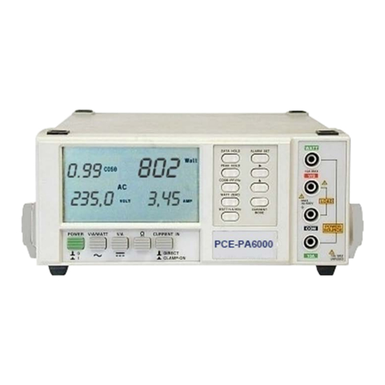
PCE-PA6000
Your purchase of this POWER ANALYZER marks a step forward
for you into the field of precision measurement. Although this
POWER ANALYZER is a complex and delicate instrument, its
durable
structure
instructions carefully and always keep this manual within easy
reach.
OPERATION MANUAL
developed.
Please
PCE Americas Inc.
711 Commerce Way
Suite 8
Jupiter
FL-33458
USA
From outside US: +1
Tel: (561) 320-9162
Fax: (561) 320-9176
info@pce-americas.com
www.pce-instruments.com/english
www.pce-instruments.com
read
the
following
PCE Instruments UK Ltd.
Unit 11
Southpoint Business Park
Ensign way
Hampshire / Southampton
United Kingdom, SO31 4RF
From outside UK: +44
Tel: (0) 2380 98703 0
Fax: (0) 2380 98703 9
info@pce-instruments.co.uk
Advertisement
Table of Contents

Related Manuals for PCE Health and Fitness PCE-PA6000


Summary of Contents for PCE Health and Fitness PCE-PA6000
- Page 1 Fax: (0) 2380 98703 9 info@pce-americas.com info@pce-instruments.co.uk ANALYZER www.pce-instruments.com/english www.pce-instruments.com PCE-PA6000 Your purchase of this POWER ANALYZER marks a step forward for you into the field of precision measurement. Although this POWER ANALYZER is a complex and delicate instrument, its durable structure developed.
- Page 2 Caution Symbol Caution : * Risk of electric shock ! * During the measurement, do not open the cabinet. Caution : * Do not apply the overload voltage, current to the input terminal ! * Remove test leads before open the battery cover ! * Cleaning - Only use the dry cloth to clean the plastic case !
-
Page 3: Table Of Contents
TABLE OF CONTENTS 1. FEATURES..............2. SPECIFICATIONS............2-1 General Specifications..........2-2 Electrical Specifications........... 3. FRONT PANEL DESCRIPTION.......... 4. PRECAUTIONS & PREPARATIONS FOR MEASUREMENT............. 5. MEASURING PROCEDURE ..........5-1 AC Watt/V/A/PF, Hz Measurement ......5-2 AC VA/V/A/PF, Hz Measurement ......5-3 AC Watt Hour ( Whr ) Measurement ....... 5-4 AC Voltage, Current Measurement ...... -
Page 4: Features
1. FEATURES * Multi-functions : WATT, VA, Whr, COS θ ( Power factor ), ACV, ACA, DCV, DCA, Hz, ohm. * True AC power( Watt ) & apparent power ( VA ) measurement. * True rms display for ACV, ACA. * 0.1 W resolution ( <... - Page 5 Measurement WATT, VA, Whr,, Power factor, ACV, ACA, DCV, DCA, Hz, ohm. Whr: Zero Adjustment External adjustment by push button. DCV, ACV, DCA, ACA : Automatic adjustment. Polarity Automatic switching, "-" indicates reverse polarity. Current input Direct input, inductive clamp probe or CT. mode Over input Indication of "...
-
Page 6: Electrical Specifications
2-2 Electrical Specifications ( 23± 5 ℃ Watt (AC, true power), current mode from direct input Range Resolution Accuracy 6,000 Watt ± ( 1.5% + 5 d ) 0.1 Watt (< 1000W) 1 Watt ( 1000W) ≧ * Accuracy is specified under the following conditions : a) AC input current is 0.05 ACA &... - Page 7 VA ( AC, Apparent Power ) current mode from direct input Range Resolution Accuracy 99.99 VA 0.01 VA ± ( 2 % + 2d ) 999.9 VA 0.1 VA 9,999 VA 1 VA * Accuracy is specified under the following conditions : a) AC input current is 0.05 ACA &...
- Page 8 AC VOLTAGE ( true rms ), DC VOLTAGE Range Resolution Accuracy 0.1 V to 299.9 V 0.1 V DCV : ± ( 1 % + 1d ) 300 V to 600 V ACV ( 10 V) : ≦ ± ( 1 % + 7d ) ACV (11 V to 100 V) : ±...
- Page 9 AC CURRENT current mode from CT ( current transformer ) Range Resolution CT 100/5A, 0.1 to 200 A 0.01 A, < 20 A 0.1 A, 20 A ≧ CT 1000/5A, 1 to 2000 A 0.1 A, < 200 A 1 A, 200 A ≧...
- Page 10 Range Resolution Accuracy 10.0 Hz to 99.9 Hz. 0.1 Hz ± ( 1 % + 1d ) 100 Hz to 999 Hz. 1 Hz * Auto range. * Frequency signal input voltage level should > 6V & 600 V. ≦ Remark : The above specifications are tested under the environment RF Field Strength less than 3 V/M &...
-
Page 11: Front Panel Description
3. FRONT PANEL DESCRIPTION Fig. 1... - Page 12 LCD Display Power Switch AC V/A/WATT Switch DC V/A Switch Ohm Switch Current In Switch WATT/VA/Whr Button Whr Zero Button COS θ ( power factor)/Hz Button 3-10 Peak Hold Button 3-11 Data Hold Button 3-12 Current Mode Button 3-13 " ^ " Button ( Alarm Set ) 3-14 "...
-
Page 13: Precautions & Preparations For Measurement
4. PRECAUTIONS & PREPARATIONS FOR MEASUREMENT 1) Ensure that the batteries are connected correctly to their snap terminals and placed in the battery compartment. 2) Select & push the correct Switch & button before marking measurements 3) Place the Test Lead into the proper input terminal before marking measurements. -
Page 14: Ac Watt/V/A/Pf/Hz Measurement
5-1 AC Watt/V/A/PF/Hz Measurement 1) Push the " Power switch " ( 3-2, Fig. 1 ) to " On " position. On = 1, Off = 0 2) Select the " AC V/A/WATT Switch " ( 3-3, Fig. 1). 3) Select the " Current In Switch " ( 3-6, Fig. 1 ) to the "... -
Page 15: Ac Va/V/A/Pf/Hz Measurement
6) * Connect the " LOAD " to the terminals of 3-17, 3-18, refer Fig. 2. * Connect the " POWER SOURCE " to the terminals of 3-16, 3-19, refer Fig. 2. 7) Power on the " Power Source " of the measured installation. -
Page 16: Ac Watt Hour ( Whr ) Measurement
5-3 AC Watt Hour ( Whr ) Measurement All the measuring procedures are same as the above " 5-1 AC Watt/V/A/PF/Hz Measurement " except should push the " WATT/VA/Whr Button " ( 3-7, Fig. 1 ) twice, then the display will show the Whr value along with the elapsed time. The Whr ( Watt Hour ) is the value of Watt x hour. -
Page 17: Dc Voltage, Current Measurement
5-5 DC Voltage, DC Current Measurement 1) Push the " Power switch " ( 3-2, Fig. 1 ) to " On " position. On = 1, Off = 0 2) Select the " DC V/A Switch " ( 3-4, Fig. 1 ). 3) Select the "... -
Page 18: Ohm Measurement
5-6 Ohm Measurement 1) Push the " Power switch " ( 3-2, Fig. 1 ) to " On " position. On = 1, Off = 0 2) Select the " Ohm Switch " ( 3-5, Fig. 1 ). 3) Connect red test lead to " V/Ohm Terminal " ( 3-17, Fig. 1 ). and black test lead to "... -
Page 19: Ac Watt, Va, Whr Measurement, Current Input Cooperate With Clamp-On Probe
Fig. 3 VOLTAGE INPUT 3-17 V/ohm 3-18 CURRENT INPUT 3-19 10 A CT ( 1000/5A, 100/5A ) 5-8 AC Watt, VA, Whr measurement, current input cooperate with Clamp-On Probe Other measurement procedures are same as the 5-1, 5-2, except : 1) Wire connection , ref. -
Page 20: Data Hold
Fig. 4 3-17 V/ohm VOLTAGE INPUT 3-18 Clamp-On Current CURRENT INPUT Input Terminals 3-20 ( Clamp-On Probe plugs ) 5-9 Data Hold During the measurement, Push the " Data Hold Button " ( 3-11, Fig. 1 ) will hold the display values & LCD will show the "... -
Page 21: Alarm Setting
5-11 Alarm Setting 1) Alarm setting function only for the " Watt " & " VA " display value. 2) " Alarm Set Button " ( 3-15 ) is used to set the Max., Min. alram value or set the alarm off ( display not show Max., Min. -
Page 22: Battery Replacement
6-1 Battery Replacement 1) When the LCD display shows the " BAT " marker, it is necessary to replace the batteries. However, in-spec. measurement may still be made for several hours after appear low battery indicator. 2) Loose the screw, slide the Battery Cover ( 3-23, Fig. 1 ), away from the instrument and remove the batteries. -
Page 23: Rs232 Pc Serial Interface
7. RS232 PC SERIAL INTERFACE The instrument features an RS232 output via 3.5 mm Terminal ( 3-22, Fig. 1). The connector output is a 16 digit data stream which can be utilized to the user's specific application. An RS232 lead with the following connection will be required to link the instrument with the PC serial input. - Page 24 D11 & D12 Annunuciator for Display Hz = 31 DCV = 34 DCA = 36 ohm = 38 K ohm = 39 Watt = 47 Hour = 61 VA = 63 Kw/hr = 65 K watt = 48 ACV = 50 ACA = 52 Minute = 62 KVA = 64...
Need help?
Do you have a question about the PCE-PA6000 and is the answer not in the manual?
Questions and answers