Table of Contents
Advertisement
Quick Links
Advertisement
Table of Contents

Related Manuals for Advantech PPC-L60T


Summary of Contents for Advantech PPC-L60T
- Page 1 Panel PC user’s Manual ed1 PPC-L60T VIA Eden Processor-based Fanless Panel PC with 6.4 TFT LCD. Contents Chapter 1 General information Chapter 2 System Setup Chapter 3 Jumper Setting and Connectors Chapter 4 Hardware Installation and Upgrading Chapter 5 Mounting Instructions...
-
Page 2: Chapter 1 General Information
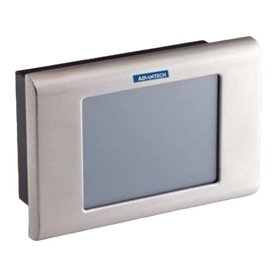
Chapter 1 General information Introduction The PPC-L60T panel PC is a VIA low-power Eden processor computer that is designed to serve as a human machine interface (HMI) and as a multimedia computer. It is a PC based system with 6.4” color TFT LCF display and. Stainless enclosure, the PPC-L60T is as compact and user friendly as a multi-function computer. -
Page 3: General Specifications
1.2General Specifications General Dimensions(WxHxD): 218x151x74.2 mm (8.58"X5.94"X2.92 ") Weight:1.8 kg (6.6 Ibs) Power supply: ATX type Input Voltage: -24 V 3.5A max. Output Voltage: 5V@5A, 12V@1A Power adaptor AC/DC Input Voltage: 100~240V ac Output Voltage:19V@3.16A Disc Driver housing: Space for one 2.5”HDD. Front Panel: IP65/NEMA compliant. - Page 4 selection and software enabled/disabled. Battery: 3.0V @ 195 Ma lithium battery Audio function Chipset: VIA82C686 South Bridge. Audio controller: AC 97 Ver.2.0 compliant interface, Multi stream direct sound and Direct Sound 3D acceleration. Stereo Sound: 18 bit full-duplex codes. Touch screen function: Type Analog Resistive Resolution...
-
Page 5: Lcd Specifications
Note: The color LCD display installed in the Panel PC is high-quality and reliable. However, it may contain a few defective pixls which don’t always illuminate. With current technology, it is impossible to completely eliminate defective pixles. Advantech is activity working to improve this technology. -
Page 6: Chapter 2 System Setup
Chapter 2 System Setup 2.1 A Quick Tour of the Panel PC Before you start to set up the Panel PC, take a moment to become familiar with location and purpose of the controls, driver, connectors and ports, which are illustrated in the figures as below. When you place the Panel PC upright on the desktop, its front panel appears as shown in the Figure 2-1. -
Page 7: Installation Procedures
2.2 Installation Procedures 2.2.1 Connecting the power Cord The Panel PC can only be powered by a DC electrical outlet 12~24 voltage, Max 3.5A). Be sure to always handle the power cord by holding the plug ends only. Please connect the male plug of the power cord to the DC inlet of the Panel PC. -
Page 8: Installing The System Software
Panel PC. Installed software requires an installed HDD. Software can be loaded in the PPC-L60T using any of two methods. 2.4.1 Method 1: Use the Ethernet You can use the Ethernet port to download software to the HDD. -
Page 9: Installing The Drivers
These files are a very useful supplement to the information in this manual. Note: The drivers and utilities used for the PPC-L60T Panel PCs are subject to change without notice. IF in doubt, check Advantech’s website or contact our application engineers for the... -
Page 10: Chapter 3 Jumper Setting And Connectors
Chapter 3 Jumper Setting and Connectors. 3.1 Jumpers The motherboard of the PPC-L60T has a number of jumpers that allow you to configure your system to suit your application. The table below lists the functions of the various jumpers. Table 3.1: Jumpers... - Page 11 Table 3.2: Connectors CN10 PC/104 expansion CN11 IDE hard drive connector CN12 COM2 port connector CN13 IR connector CN14 Audio connector CN15 Parallel port connector CN16 Power & HDD LED connector CN17 Ethernet connector CN18 Keyboard and PS/2 mouse connector CN19 USB channel 1, 2 connector CN20...
- Page 12 3.3 Locating jumpers Figure 3.1: Jumper locations...
- Page 13 3.4 Locating Connectors Figure 3.2: Connectors (component side) Chapter...
- Page 14 Figure 3.3: Connectors (solder side)
- Page 15 3.5 Setting Jumpers You may configure your panel PC to match the needs of your application by setting jumpers. A jumper is a metal bridge used to close an electric cir- cuit. It consists of two metal pins and a small metal clip (often protected by a plastic cover) that slides over the pins to connect them.
- Page 16 3.6 Clear CMOS (S2) Warning! To avoid damaging the computer, always turn off the power supply before setting “Clear CMOS.” Before turning on the power supply, set the jumper back to “3.0 V Battery On.” This jumper is used to erase CMOS data and reset system BIOS informa- tion.
- Page 17 3.7 COM port connector (CN20,CN12) The motherboard of PPC-L60T provides two serial ports (COM1: RS-232; COM2: RS- 232/422/485) in one DB-9 connector (COM1) and one 14-pin dual-inline, male header. It provides connections for serial devices (a mouse, etc.) or a communication network. You can find the pin assignments for the COM port connector in Appendix C.
- Page 18 3.9 Watchdog timer configuration An on-board watchdog timer reduces the chance of disruptions which EMP (electro-magnetic pulse) interference can cause. This is an invalu- able protective device for standalone or unmanned applications. Setup involves one jumper and running the control software (refer to Appendix 2.21.1 Watchdog timer action (pin 7-10 of JP1) When the watchdog timer activates (CPU processing has come to a halt), it can reset the system or generate an...
-
Page 19: Chapter 4 Hardware Installation And Upgrading
Chapter 4 Hardware Installation and Upgrading 4.1 Introduction The panel PC consists a PC-based computer that is housed in a metal rear cover and. You can install HDD, SDRAM and CF card by removing the rear panel. Any maintenance or hardware upgrades can be easily completed after removing the rear panel and HDD bracket. - Page 20 Fig 4-1 Fig 4-2...
- Page 21 Fig 4-3 Fig 4-4...
-
Page 22: Chapter 5 Mounting Instructions
Chapter 5 Mounting Instructions 5.1 Panel Mounting The PPC-L60T can be mounted into a panel. Panel Mounting can help system integrators conveniently integrate the Panel PC in their system. To construct a suitable panel, refer the following cutout dimensions diagram. -
Page 23: Installation Procedure
5.1.2 Installation procedure To mount the PPC-L60T into the Panel: Panel Mount (1) Panel Mount 1. There are seven holes located along the four sides of the Panel 2. Insert the screws from the front side into the holes and tighten them with the nuts provided.(See Figure E.2 ) - Page 24 Figure 5.2 Panel Mounting...
-
Page 25: Cut-Out Area
Figure 5.3 Panel Mounting 5.1.3 Cut-out area Refer to Figure 5-3 below for the locations and dimensions for the cut out area and mounting holes. - Page 26 Figure 5.3: Dimension of Panel mounting holes.
Need help?
Do you have a question about the PPC-L60T and is the answer not in the manual?
Questions and answers