Table of Contents
Advertisement
Quick Links
Advertisement
Table of Contents

Related Manuals for Advantech PPC-L61T


Summary of Contents for Advantech PPC-L61T
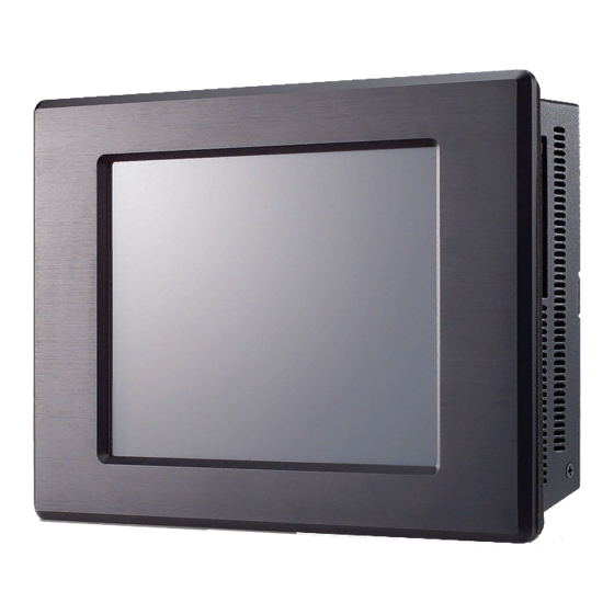
- Page 1 User Manual PPC-L61T AMD LX800 Processor based Fanless Panel PC with 6.5” TFT...
- Page 2 Microsoft Windows is a registered trademark of Microsoft Corp. RTL is a trademark of Realtek Semi-Conductor Co., Ltd. All other product names or trademarks are properties of their respective owners. For more information on this and other Advantech products, please visit our websites http://www.advantech.com http://www.advantech.com.tw For technical support and service, please visit our support website at: http://service.advantech.com.tw/eservice...
-
Page 3: Declaration Of Conformity
Consult the dealer or an experienced radio/TV technician for help. Warning! Any changes or modifications made to the equipment which are not expressly approved by the relevant standards authority could youíre your authority to operate the equipment. PPC-L61T User Manual... -
Page 4: Packing List
If any of these items are missing or damaged, contact your distributor or sales repre- sentative immediately. Additional Information and Assistance Visit the Advantech web site at www.advantech.com/support where you can find the latest information about the product. Contact your distributor, sales representative, or Advantech's customer service center for technical support if you need additional assistance. -
Page 5: Safety Instructions
The sound pressure level at the operator's position according to IEC 704-1:1982 is no more than 70 dB (A). DISCLAIMER: This set of instructions is given according to IEC 704-1. Advantech disclaims all responsibility for the accuracy of any statements contained herein. - Page 6 Anweisung des Herstellers. Der arbeitsplatzbezogene Schalldruckpegel nach DIN 45 635 Teil 1000 beträgt 70dB(A) oder weiger. Haftungsausschluss: Die Bedienungsanleitungen wurden entsprechend der IEC- 704-1 erstellt. Advantech lehnt jegliche Verantwortung für die Richtigkeit der in diesem Zusammenhang getätigten Aussagen ab. PPC-L61T User Manual...
-
Page 7: Table Of Contents
System Setup ........5 A Quick Tour of the Panel PC ..............6 Figure 2.1 Front View of the PPC-L61T Panl PC ......6 Figure 2.2 Left Side of the PPC-L61T.......... 6 Figure 2.3 Rear View of the PPC-L61T ........7 Figure 2.4 Panel PC I/O............... - Page 8 Table 4.5: COM port Pin 9 power output setting (CN13)... 22 4.3.2 COM port Pin 9 power output value setting (CN10) ....22 Table 4.6: COM port Pin 9 power output value setting (JP2) ..22 PPC-L61T User Manual viii...
-
Page 9: Chapter 1 General Information
Chapter General Information This chapter gives background information on the PPC-L61T Panel PC. Sections include: Introduction General Specifications LCD Specifications Dimensions... -
Page 10: Introduction
Introduction The PPC-L61T panel PC is an AMD low-power LX800 processor computer that is designed to serve a Human machine interface (HMI) and as a multimedia computer. It is a PC based system with 6.5"color TFT LCD display and aluminum front cover, the PPC-L61T is as compact and user friendly as a multi-function computer. - Page 11 – Wall Mount kit: PPC-174 WL-MT – Panel Mount kit: Included in standard purchase of PPC-L61T Extension SATA HDD Kit (without HDD): 989KL61T00E. 19 V / 60 W AC Adapter: 1757000272 Power cord: 1702002600 (USA type), 1702002605( Euro type), 1700000237 (JP type), 1700000596 (China type) Wireless LAN kit (802.11 b.g ): 989KL12709E...
-
Page 12: Lcd Specifications
The color LCD display installed in the Panel PC is high-quality and reli- able. However, it may contain a few defective pixels which do not always illuminate. With current technology, it is impossible to completely eliminate defective pixels. Advantech is actively working to improve this technology. Dimensions 186.00... -
Page 13: Chapter 2 System Setup
Chapter System Setup This chapter details system setup on the PPC-L61T Panel PC. Sections include: A quick Tour on Panel PC Installation procedures Running the BIOS Setup Pro- gram Installing System Software Installing the Drivers... -
Page 14: A Quick Tour Of The Panel Pc
When you place the Panel PC upright on the desktop, its front panel appears as shown in Figure 2.1. Figure 2.1 Front View of the PPC-L61T Panl PC When you look at the left side of the Panel PC, you will see the Complat Flash socket at left side as shown in Figure 2.2. -
Page 15: Figure 2.3 Rear View Of The Ppc-L61T
(75x75mm) and power Button. As shown in Figure 2.3. Product Lable Power Button Figure 2.3 Rear View of the PPC-L61T The I/O section is at the bottom of the Panel PC, as shown in Figure 2.4. Figure 2.4 Panel PC I/O... -
Page 16: Installation Procedures
CMOS RAM and compares them to the equipment check conducted during the power on self-test (POST). If an error occurs, an error message will be displayed on screen, and you will be prompted to run the setup program. PPC-L61T User Manual... -
Page 17: Installing System Software
Chapter 5 to 10 of this manual. Note! The drivers and utilities used for the PPC-L61T are subject to change without notice. If in doubt, check Advantech’s website or contact our application engineers for the latest information regarding drivers and utilities. - Page 18 PPC-L61T User Manual...
-
Page 19: Chapter 3 Hardware And Peripheral Installation
Chapter Hardware and Peripheral Installation This chapter details the installation of the PPC-L61T hardware. Sections include: Overview of Hardware Installation and upgrading Installing the Storage Device and Memory Installing the Optional accessory... -
Page 20: Overview Of Hardware Installation And Upgrading
Put the CFC into the CF slot and insert the RAM into the 200-pin SODIMM socket on the main board. Installing the Optional accessory Optional accessories, like Extension HDD kit or other functional modules are avail- able for purchase to complement PPC-L61T. The following are instructions for acces- sory installation. 3.3.1 Installing Extension HDD kit Place the HDD on the HDD mounting Bracket and tighten the screws. - Page 21 Plate the HDD Module into HDD Cover and tighten the screws. Detach and Remove the Rear cover. Remove the SATA HDD hole through (-) Screwdriver. Attach the SATA converter board to the Rear cover with two M2*5 screws. Connect the IDE HDD cable to the SATA converter. PPC-L61T User Manual...
- Page 22 Connect SATA cable to the SATA Converter board through the hole. Fix the SATA cable with green adhesive tape. Attach HDD cover on PPC-L61 back cover with Four M3*5 screws. Attached VESA Bracket to the HDD. Put the Rear cover on and tighten the screws. PPC-L61T User Manual...
-
Page 23: Installing The Minipci Wireless Lan Module
Tight the cable between the connector (main) on the WLAN module and the screw-in antenna hole on Middle Frame. Screw the antenna on the antenna hole on Middle Frame shown as below pic- ture. WLAN (Mini PCI) Power Power Switch PPC-L61T User Manual... - Page 24 PPC-L61T User Manual...
-
Page 25: Chapter 3
Chapter Jumper Settings and Connectors This chapter tells how to set up the Panel PC hardware, including instructions on setting jumpers and connecting peripherals, switches and indicators. Be sure to read all the safety precautions before you begin the installation procedures. -
Page 26: Setting Jumpers
4.1.1 Jumpers and Switches on Motherboard The motherboard of the PPC-L61T has a number of jumpers and Connector that allow you to configure your system to suit your applications. The table below lists the function of each jumper and Connector. -
Page 27: Locating Jumpers On Motherboard
Touch screen connector Inverter connector CN11 COM 3 / GPIO CN16 CN17 USB 1+USB 2 CN18 DC input CN19 COM2 / RS232/422/485 CN20 COM1 CN21 CN22 LVDS interface CN23 DIMM1 Dual In-line Memory Module Socket for SDRAM PPC-L61T User Manual... -
Page 28: Locating Connectors On Motherboard
4.1.4 Locating Connectors on Motherboard Figure 4.2 Locating Connectors on the PPC-L61T Mother-board (front side) Figure 4.3 Locating Connectors on the PPC-L61T Mother-board (back side) PPC-L61T User Manual... -
Page 29: Jumper Setting On Mother-Board
Clear CMOS 4.2.2 AT/ATX power Setting Power feature setting (J1) The default setting for PPC-L61T is ATX Mode, client can easy to adjust Power Mode to AT by jumper setting. Described as below: Table 4.4: AT/ATX Power setting (J1) ATX Power Model (Default) -
Page 30: Com Port Interface
The normal external power output value is DC 5 V 4.3.2 COM port Pin 9 power output value setting (CN10) Table 4.6: COM port Pin 9 power output value setting (JP2) 5 V (Default) 12 V (Optional) PPC-L61T User Manual... - Page 31 PPC-L61T User Manual...
- Page 32 No part of this publication may be reproduced in any form or by any means, electronic, photocopying, recording or otherwise, without prior written permis- sion of the publisher. All brand and product names are trademarks or registered trademarks of their respective companies. © Advantech Co., Ltd. 2007...
Need help?
Do you have a question about the PPC-L61T and is the answer not in the manual?
Questions and answers