
Related Manuals for Advantech PPC-L158T


Summary of Contents for Advantech PPC-L158T
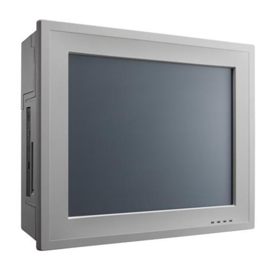
- Page 1 User Manual PPC-L158T Intel Atom Processor- Based Panel PC with 15” Color TFT LCD Display...
- Page 2 No part of this manual may be reproduced, copied, translated or transmitted in any form or by any means without the prior written permission of Advantech Co., Ltd. Information provided in this manual is intended to be accurate and reliable. How- ever, Advantech Co., Ltd.
-
Page 3: Declaration Of Conformity
This product has passed the CE test for environmental specifications when shielded cables are used for external wiring. We recommend the use of shielded cables. This kind of cable is available from Advantech. Please contact your local supplier for ordering information. -
Page 4: Safety Instructions
For use only with UL Listed Wall Mount Bracket with minimum weight/load 6 kg or equivalent. DISCLAIMER: This set of instructions is given according to IEC 704-1. Advantech disclaims all responsibility for the accuracy of any statements contained herein. PPC-L158T User Manual... - Page 5 Don't touch any components on the CPU card or other cards while the PC is on. Disconnect power before making any configuration changes. The sudden rush of power as you connect a jumper or install a card may damage sensitive elec- tronic components. PPC-L158T User Manual...
- Page 6 PPC-L158T User Manual...
-
Page 7: Table Of Contents
........5 A Quick Tour of the Panel PC ..............6 Figure 2.1 Front Panel of PPC-L158T ......... 6 Figure 2.2 Side View of the Panel PC ......... 6 Figure 2.3 I/O Peripheral Connectors Panel of AC Input Model .. 7 Figure 2.4 I/O Peripheral Connectors Panel of DC Input Model.. -
Page 8: Chapter 5 Jumpers And Connectors
Table 5.1: JP1 (CMOS Setting & AT / ATX Select)....33 Table 5.2: CN19(Ring and Power for COM1/2 pin 9)....33 5.1.3 Jumper and Connector Locations..........34 Figure 5.1 Jumpers & Connectors on PPC-L158T Motherboard... 5.1.4 Connectors ................. 35 Table 5.3: CN1 (LVDS Back Light)..........35 Table 5.4: CN2/3 (SATA Power) .......... - Page 9 Chapter Driver Installation ......43 Introduction ..................... 44 6.1.1 Driver Installation ................ 44 Updating Driver Search on the Advantech Website........ 44 Appendix A PCI Card and PCIe Size Limits ..45 PCIe Interface Card ................46 PCI Interface Card .................. 46 Add-on Card.................... 47...
- Page 10 PPC-L158T User Manual...
-
Page 11: Chapter 1 General Information
Chapter General Information This chapter gives background information on the PPC-L158T. Sections include: Specifications Dimensions... -
Page 12: Introduction
1.1 Introduction Advantech PPC-L158T is an Intel Atom processor based Panel PC with a bright 15" LCD display. The powerful Atom CPU and Intel ICH8M chipsets bring the most dynamic applications to life without sacrifices to any industrial reliability. The Internal... -
Page 13: Touchscreen Specifications (Optional)
Temperature: 0 ~ 50° C (32 ~ 122° F) Relative humidity: 10 ~ 95% @ 40° C (non-condensing) Shock: 10 G peak acceleration (11 msec duration) 1.2.9 Certifications: EMC: CE, FCC, BSMI, CCC Safety: CE, CB, UL, BSMI, CCC, VCCI PPC-L158T User Manual... -
Page 14: Dimensions
1.3 Dimensions Figure 1.1 Dimensions of PPC-L158T PPC-L158T User Manual... -
Page 15: Chapter 2 System Setup
Chapter System Setup This chapter gives system setup information for the PPC-L158T. Sections include: A Quick Tour Installation Procedures Running the BIOS Setup Installing System software... -
Page 16: A Quick Tour Of The Panel Pc
When placed upright on the desktop, the front panel of the panel PC appears as shown in Figure 2.1. Figure 2.1 Front Panel of PPC-L158T When viewed from the left side of the panel PC, the optical device drive, USB ports are visible, as shown in Figure 2.2. -
Page 17: Figure 2.3 I/O Peripheral Connectors Panel Of Ac Input Model
G: PS2 Mouse x 1 / Keyboard x 1 H :Power Swith I: DC Inlet J: RS-232 x 1 (or GPIO x 1 by cable swapping) K: 10/100/1000 Mbps Ethernet x 1 L: PCI Slot x 1 (or PCIe Slot x 1) PPC-L158T User Manual... -
Page 18: Figure 2.5 Rear View Of The Panel Pc
VESA standard, both 100 x 100 mm and 75 x 75 mm mounting size. Figure 2.5 Rear View of the Panel PC Caution! Use recommended mounting apparatus to avoid risk of injury. PPC-L158T User Manual... -
Page 19: Preparing For First-Time Use
The guidelines below will help determine the steps necessary to install the operating system onto the panel PC hard drive. Note! Some distributors and system integrators may have already pre- installed system software prior to shipment. PPC-L158T User Manual... -
Page 20: Installing The Drivers
Figure 2.6 Drivers and Utilities on the CD-ROM Note! The drivers and utilities used for the PPC-L158T panel PCs are subject to change without notice. If in doubt, check Advantech's website or con- tact our application engineers for the latest information regarding drivers utilities. -
Page 21: Chapter 3 Using The Panel Pc
Chapter Using the Panel PC This chapter explains onboard devices and peripheral I/O ports available on the PPC-L158T. Sections include: CD-ROM Drive PS/2 Mouse and Keyboard PCI or PCIe Bus Expansion Serial COM Ports VGA Port ... -
Page 22: Introduction
To insert a CD-ROM disc, press the eject button on the CD-ROM drive. To eject a CD-ROM disc, first ensure that the drive activity light is not active. Then press the eject button on the drive. Figure 3.1 Inserting and ejecting a CD-ROM PPC-L158T User Manual... -
Page 23: Ps/2 Mouse And Keyboard
Remove the metal plate by unscrewing the attaching screw. Insert the PCI or PCIe into the PCIe slot of the riser card. (See Figure 3.2) Run the setup program within the OS to configure the system. Figure 3.2 PCI & PCIe Bus Expansion PPC-L158T User Manual... -
Page 24: Serial Com Ports
Refer to the manual(s) which accompanied any serial device(s) for instructions on configuring the operating environment to recognize the device(s). Run the BIOS setup program and configure the jumper settings to change the mode of the COM ports. Figure 3.3 I/O Ports PPC-L158T User Manual... -
Page 25: Vga Port
3.10 Touchscreen (Optional) The touchscreen is connected to the internal USB port. Its function is similar to that of a mouse. PPC-L158T supports resistive touchscreen. It is necessary to install the touchscreen driver before it will function. The touch- screen drivers for various operating systems are stored on the CD-ROM disc inside the accessory box. - Page 26 PPC-L158T User Manual...
-
Page 27: Chapter 4 Hardware Installation
Chapter Hardware Installation This chapter gives instructions for installing hardware devices on the PPC-L158T. Sections include: Jumpers and Connectors Disassembling the Panel PC Installing the Central Processing Unit (CPU) Installing the DDR3 SDRAM Memory Module... -
Page 28: Jumpers And Connectors
The following are standard procedures for disassembling the panel PC before upgrading the system. All procedures are illustrated in Figure 4.1. Unfasten the screws securing the rear plastic cover and remove it. Figure 4.1 Unfastening the Rear Cover PPC-L158T User Manual... -
Page 29: Figure 4.3 The Ppc Hdd
Remove the two screws on side cover first. (See Figure 4.2) Figure 4.2 The PPC Side Cover Remove the four screws on the metal plate on both sides of the HDD. (See Fig- ure 4.3) Figure 4.3 The PPC HDD PPC-L158T User Manual... -
Page 30: Figure 4.4 Plugging In The Sata Cable
Connect the SATA cable from the mainboard. Figure 4.4 Plugging in the SATA Cable PPC-L158T User Manual... -
Page 31: Installing The Ddr3 Sdram Memory Module
The panel PC system provides two 204-pin SODIMM sockets and it is possible to install 4 GB of DDR3 SDRAM memory. Figure 4.5 Placing the Memory Module in the SODIMM Socket Figure 4.6 Stick the Thermal Pad on the Memory Heatsink PPC-L158T User Manual... -
Page 32: Figure 4.7 Fasten The Memory Heatsink Onto The Board
Figure 4.7 Fasten the Memory Heatsink onto the Board PPC-L158T User Manual... -
Page 33: Installing The Optical Device Drive
4.5 Installing the Optical Device Drive Remove all the screws on the rear cover. Figure 4.8 Rear Cover Photo Plug in the SATA ODD cable. Figure 4.9 Plug in the SATA ODD Cable PPC-L158T User Manual... -
Page 34: Figure 4.10Fasten Screw On Io Shielding
Place ODD on device bracket, then fasten screws on IO shielding. Figure 4.10 Fasten Screw on IO Shielding Fasten screws on the ODD bracket. Figure 4.11 Fasten Screws on the ODD Bracket PPC-L158T User Manual... -
Page 35: Installing Gpio Cable
The GPIO cable uses same cable as COM4 Figure 4.12, so just change the cable PIN header from CN18 to CN11, see Figure 4.13. Figure 4.12 GPIO Location on I/O Bracket Figure 4.13 Change Cable PIN Header to CN11 PPC-L158T User Manual... -
Page 36: Installing The Lpt Cable
I/O bracket, and insert the LPT cable PIN header on the motherboard CN37 location. Figure 4.14 Insert LPT Cable PIN Header on the Motherboard Assemble the device bracket, then fasten the LPT cable bracket on the I/O bracket. PPC-L158T User Manual... -
Page 37: Figure 4.15Fix The Lpt Cable On The I/O Bracket
Figure 4.15 Fix the LPT Cable on the I/O Bracket Remember to secure the LPT bracket and I/O bracket with a screw. Figure 4.16 Fasten the Screw on the Bracket The completed LPT cable assemblage below. Figure 4.17 Completed Photo of LPT Cable Assemblage PPC-L158T User Manual... -
Page 38: Installing Dual-Usb Cable
PIN header on motherboard CN9 or CN10 location. Figure 4.18 Insert Dual-USB Cable on CN9 or CN10 Assemble the device bracket, then fasten the dual-USB cable bracket on the I/O bracket. PPC-L158T User Manual... -
Page 39: Figure 4.19Dual-Usb Cable Assembly On I/O Bracket
Figure 4.19 Dual-USB Cable Assembly on I/O Bracket Remember to secure dual-USB bracket and I/O bracket with a screw. Figure 4.20 Fasten Screw on Bracket PPC-L158T User Manual... -
Page 40: Figure 4.21Completed Assembled Dual-Usb Cable
Completed assembly as below. Figure 4.21 Completed Assembled Dual-USB Cable PPC-L158T User Manual... -
Page 41: Connectors
Chapter Jumpers and Connectors This chapter gives information on setting jumpers and using the connectors on the PPC-L158T motherboard. Sections include: Setting Jumpers Jumpers and Connectors loca- tions Connectors... -
Page 42: Jumpers And Connectors
5.1 Jumpers and Connectors This chapter supplies more detailed information about the internal jumper settings and an outline of the I/O ports available on the PPC-L158T. 5.1.1 Setting Jumpers The Panel PC can be configured to match the needs of each application by setting jumpers. -
Page 43: Jumpers
It also has LED indicator lights that display the system operation status. The table below lists the function of each jumper and LED. The motherboard of the PPC-L158T has a number of jumpers that allow you to con- figure your system to suit your applications. -
Page 44: Jumper And Connector Locations
5.1.3 Jumper and Connector Locations CN12 CN13 CN14 CN9/10 CN37 CN19 CN16 CN18 CN35 CN21 CN20 CN22 CN23 CN34 CN25 CN31 CN30 CN11 CN29 CN28 CN32 CN33 CN24 CN26/27 Figure 5.1 Jumpers & Connectors on PPC-L158T Motherboard PPC-L158T User Manual... -
Page 45: Connectors
CN23 Speak CN24 LAN1&USB01 CN25 CN26/27 13940/1 CN28 LAN2 CN29 USB23 CN30 COM1&VGA CN31 COM23 CN32 MIC IN CN33 LIN OUT CN34 DC IN (For DC) Table 5.3: CN1 (LVDS Back Light) Pin Name +V12_INVERTER BKLT_EN LVDS0_CTLBK PPC-L158T User Manual... -
Page 46: Table 5.4: Cn2/3 (Sata Power)
Table 5.4: CN2/3 (SATA Power) Pin Name +V3.3 +V12 Table 5.5: CN4/5 (SATA0/1) Pin Name SATA1_TX+ SATA1_TX- SATA1_RX- SATA1_RX+ Table 5.6: CN6 (LVDS) Pin Name LVDS0_z_D0- LVDS0_z_D0+ LVDS0_z_D1- LVDS0_z_D1+ LVDS0_DDC_SD LVDS0_z_D2- LVDS0_z_D2+ LVDS0_DDC_SC LVDS0_z_CLK- LVDS0_z_CLK+ +V_LCD +V_LCD PPC-L158T User Manual... -
Page 47: Table 5.7: Cn7 (Minipcie)
Pin Name +V5_USB +V5_USB USB4//6_P- USB5/7_P- USB4//6_P+ USB4//6_P+ 7~10 Table 5.9: CN11 (GPIO) Pin Name GPIO4 GPIO0 GPIO5 GPIO1 GPIO6 GPIO2 GPIO7 GPIO3 Table 5.10: CN12/13 (Memory 0/1) Standard connect Table 5.11: CN14 (T/S) Standard connect SENSE PPC-L158T User Manual... -
Page 48: Table 5.12: Cn18 (Com4)
Table 5.13: CN20 (LED Connect) Pin Name LAN2_LED0 LAN1_LED0 SATA_LED# Table 5.14: CN21 (Button) Pin Name PWRBTN# Table 5.15: CN22 (DC IN (For 12V)) Pin Name DC_IN (+12v) DC_IN (+12v) Table 5.16: CN23 (Speak) Pin Name AUD_OA- AUD_OA+ AUD_OB+ AUD_OB- PPC-L158T User Manual... -
Page 49: Table 5.18: Cn25 (Ps2)
XTPBM XTPBP XTPAM XTPAP Table 5.20: CN28 (LAN2) Pin Name MDI0+ MDI0- MDI1+ MDI1- VDC1 VDC2 MDI2+ MDI2- MDI3+ MDI3- +3.3V ACT# LINK1000# LINK100# Table 5.21: CN29 (USB23) Pin Name +V5_USB USB2_P- USB2_P+ +V5_USB USB5/7_P- USB4//6_P+ 8~12 PPC-L158T User Manual... -
Page 50: Table 5.22: Cn30 A (Com1 Rs232)
Table 5.22: CN30 A (COM1 RS232) Pin Name COM1_DCD COM1_RXD COM1_TXD COM1_DTR COM1_DSR COM1_RTS COM1_CTS Table 5.23: CN30B VGA Standard Connect Table 5.24: CN31 A (COM2 RS232/422/485 Select by BIOS) Pin Name RS232 RS422 RS485 422_TXD- 485_Data- 422_TXD+ 485_Data+ 422_RXD+ 422_RXD- PPC-L158T User Manual... -
Page 51: Table 5.25: Cn31 B (Com3 Rs-232 Serial Port)
DSR# RTS# CTS# Table 5.26: CN32 (MIC IN) Pin Name GND_AUD MIC1_z_L GND_AUD MIC_JD MIC1_z_R Table 5.27: CN33 (LINE OUT) Pin Name GND_AUD LOUT_z_L GND_AUD FRONT_JD LOUT_z_R Table 5.28: CN34 (DC IN (For DC)) Pin Name DC_IN PPC-L158T User Manual... - Page 52 PPC-L158T User Manual...
-
Page 53: Chapter 6 Driver Installation
Chapter Driver Installation This chapter gives information on installing drivers for the PPC- L158T. Sections include: Driver Installation Updating Drivers... -
Page 54: Introduction
Before installing the Ethernet driver, note the procedures below. It is necessary to know which operating system is installed on the PPC-L158T. Then refer to the corre- sponding installation flow chart. Follow the steps described in the flow chart to com- plete the installation quickly. -
Page 55: Appendix Apci Card And Pcie Size Limits
Appendix PCI Card and PCIe Size Limits This chapter details the size limits for PCI and PCIe cards that may be installed on the Panel PC moth- erboard. -
Page 56: Pcie Interface Card
A.1 PCIe Interface Card A.2 PCI Interface Card PPC-L158T User Manual... -
Page 57: Add-On Card
A.3 Add-on Card PPC-L158T User Manual... - Page 58 PPC-L158T User Manual...
- Page 59 No part of this publication may be reproduced in any form or by any means, electronic, photocopying, recording or otherwise, without prior written permis- sion of the publisher. All brand and product names are trademarks or registered trademarks of their respective companies. © Advantech Co., Ltd. 2011...
Need help?
Do you have a question about the PPC-L158T and is the answer not in the manual?
Questions and answers