Rosslare AC-Q4 Series Instruction Manual
Vandal resistant stand-alone controllers
Hide thumbs
Also See for AC-Q4 Series:
- Installation and programming manual (57 pages) ,
- Installation and programming manual (57 pages)

Related Manuals for Rosslare AC-Q4 Series


Summary of Contents for Rosslare AC-Q4 Series
- Page 1 AC-Q4x Family Vandal Resistant Stand-Alone controllers Instruction Manual Models: AC-Q41H/HB AC-Q41SB AC-Q42H/HB AC-Q42SB AC-Q44 December 2006...
-
Page 3: Table Of Contents
Table of Contents Table of Contents General Information............4 INTRODUCTION ................4 CONTROLLER TYPES..............4 BOX CONTENT ................. 5 ANCILLARY EQUIPMENT .............. 5 TECHNICAL SPECIFICATIONS ............6 KEY FEATURES ................7 FRONT PANEL DESCRIPTION ............8 Installation ................9 MOUNTING THE CONTROLLER ........... 9 WIRING THE CONTROLLER ............ - Page 4 Table of Contents Pr gramming ..............26 INTRODUCTION ................26 4.1.1 Entering the Programming Mode ..........28 4.1. Exiting the Programming Mode ............ 28 CHANGING THE OPEN CODE ............29 CHANGING THE AUXILIARY CODE .......... 29 CHANGING THE PROGRAMMING CODE........30 CHANGING THE NORMAL/SECURE CODE ......
-
Page 5: General Information
General Information General Information INTRODUCTION The AC-Q4x series Access Control units are vandal resistant stand- alone controllers. All the units are water resistant and suitable for indoor or outdoor mounting. The unit(s) accepts up to 500 users and allows entry via a personal identification number (PIN) and / or by presenting a proximity card. -
Page 6: Box Content
General Information BOX CONTENT Before beginning verify that all of the following is in the box, if anything is missing please report the discrepancy to your nearest Rosslare Office. • One unit • One Drilling Template (Label/Sticker) • One security spline key •... -
Page 7: Technical Specifications
General Information TECHNICAL SPECIFICATIONS AC-Q41H AC-Q41HB AC-Q42H AC-Q42HB AC-Q41SB AC-Q42SB AC-Q44 Input Voltage 12-24 VDC 12-24 VAC 16-24 VAC 12-24 VAC 16-24 VAC Maximum Input Heater Off 100mA 130mA 125mA 145mA 130mA 145mA 125mA Current (12VDC) Heater On 580mA 610mA 605mA 625mA 610mA... -
Page 8: Key Features
General Information KEY FEATURES • 500 Users • Water and vandal resistant • Programmable Backlight and active LED control (option “B”) • Three user levels: normal; secure; master • Three modes of operation: normal; bypass; secure • Integrated keypad for PIN entry (Piezoelectric - Q44 only) •... -
Page 9: Front Panel Description
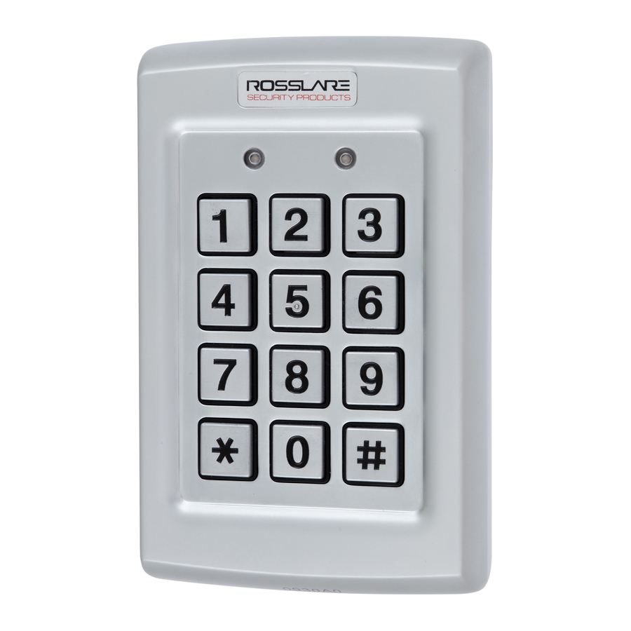
General Information FRONT PANEL DESCRIPTION Controls and indicators of all controller versions are identical. See Figure 1 (excluding the antenna, which is unique to Q42 and Q44). Figure 1: Front Panel AC-Q4x Family, Installation and user Manual Page 8... -
Page 10: Installation
Installation Installation MOUNTING THE CONTROLLER Prior to starting, select the location where the controller unit is to be mounted. Perform the following steps: 1) Open the controller by loosening and removing the case security screw at the bottom using the security spline key. Depending on the type of installation, gang box or panel mount, drill the respective holes in the rear cover. -
Page 11: Wiring The Controller
Installation Use the provided drilling template to accurately locate and drill the required holes in the wall or panel. Use the hardware provided to mount the back plate on the wall or on a gang box. Be sure to route the wiring via the large center hole in the back plate. - Page 12 Installation Wiring Color Guide Color Description V input Black Ground Green REX / BL White In / Monitor Purple Lock: Com Gray Lock: N.O. Brown Lock: N.C. Blue Aux: Com Yellow Aux: N.O. Orange Aux: N.C. Page 11 AC-Q4x Family, Installation and user Manual...
- Page 13 Installation Figure 3: Pre-Wired Connection for Lock Strike Relay & REX AC-Q4x Family, Installation and user Manual Page 12...
- Page 14 Installation Figure 4: Pre-Wired Connection for Auxiliary Input & Output Page 13 AC-Q4x Family, Installation and user Manual...
- Page 15 Installation Figure 5: Pre-Wired Connection for the BL-D40 External Sounder AC-Q4x Family, Installation and user Manual Page 14...
-
Page 16: Terminal Block Models
Installation 2.2.2 Terminal Block Models These controllers come with removable terminal blocks that are pushed on pins on the motherboard of the controllers. Wire according to the following steps: Route the wires or cable through the large hole in the back cover See Figure 6. - Page 17 Installation Figure 7: Terminal Block Wiring of the Lock Strike Relay & REX AC-Q4x Family, Installation and user Manual Page 16...
- Page 18 Installation Figure 8: Terminal Block Wiring of the Auxiliary Input & Output Page 17 AC-Q4x Family, Installation and user Manual...
- Page 19 Installation Figure 9: Terminal Block Wiring of the BL-D40 External Sounder AC-Q4x Family, Installation and user Manual Page 18...
-
Page 20: Operation
Operation Operation Note: • In the Operation chapter, “code” refers to a PIN code or proximity card depending on the unit you have. • Memory slots can be a proximity card or PIN code depending on the unit you have. MODES OF OPERATION The Control units have three modes of operation. -
Page 21: Bypass Mode
Operation 3.1.3 Bypass Mode • Mode indicator is orange. In bypass mode, access to the premises is dependent on the Lock Strike relays; that is, if the relay is programmed for failsafe operation or fail-secure operation. When the Lock Strike relay is programmed for fail secure operation, the door is locked until the star button ( ) is depressed. -
Page 22: Secure User
Operation 3.2.2 Secure User A secure user must have a primary and secondary code assigne and the two codes must not be the same . The secure user can n access in any mode of operation. In normal mode the secure er must use th e primary code to gain entry. -
Page 23: From Secure To Normal Mode
Operation 3.3.2 From Secure to Normal Mo faul t factory setting for the normal / se cure code is 3838. Ente r the normal / secure code. Mode Door • Mode indicator will flash green. Mode Door Green 2) Depress the # key to confirm the Mode Mode Door change. -
Page 24: From Bypass To Normal Mode
Operation 3.3.4 From Bypass to Normal Mode Ent r the normal / bypass code. Mode Door Orange Mode Door • Mode indicator will flash green. Green 2) Depress the # key to confirm the mode change. • Mode indicator will turn green. Mode Door Green... -
Page 25: Tamper Feature
Operation Fail Secure Operation: from the moment the REX pushbutton depressed, the door will be unlocked until the Lock Strike release time has elapsed. After this time, the door will be locked, even if the REX pushbutton has not been released. Failsafe Operation: from the moment the REX pushbutton is depressed, the door will be un locked until the REX pushbutton is leased. -
Page 26: Bl-D40 External Sounder
(opened or removed from the wall). The length of the siren can also be programmed in the controller. The controller communicates with the BL-D40 via a Rosslare proprietary protocol. If the BL-D40 receives an unrecognized code over its communication line or communications between the controller and the BL-D40 are severed, the strobe will flash repeatedly, until the communication problem has been resolved. -
Page 27: Pr Gramming
Programming Programming Note: • In the Programming chapter, “code” refers to a PIN code or proximity card depending on the unit you have. • When entering a PIN or presenting a proximity card is mentioned, the meaning may vary between units. INTRODUCTION Programming an AC-Q4x series Access Control unit is done solely via the unit’s keypad-driven Programming Menu System. - Page 28 Programming The table below shows all the programming menus, with default factory codes and settings. Menu Description Default Page No. 4 Digit 5 Digit 6 Digit 4-8 Digits Change open code 2580 25802 258025 25802580 Change auxiliary code 0852 08520 085208 08520852 Change program code...
-
Page 29: Entering The Programming Mode
Programming 4.1.1 Entering the Programming Mode Note: • The controller must be in normal mode to enter the programming mode. • The factory default 4-digit programming code is 1234. • If a programming code is not entered within 5 seconds, the controller will return to its normal mode. -
Page 30: Changing The Open Code
Programming CHANGING THE OPEN CODE The open code is mainly used as a method to quickly test the Lock Strike relay during installation. The factory 4-digit default setting for the open code is 2580. For security reasons when the first user is added to the controller or the auxiliary code is changed, the default open code will automatically be deleted, non-default codes will not be erased automatically. -
Page 31: Changing The Programming Code
Programming Note: • Auxiliary code does not function in secure mode. • Auxiliary code only works when the auxiliary mode is 0, 1, 8 or 9. • Wrong entries: you will hear a long beep and the controller will return to its normal mode. •... -
Page 32: Changing The Normal/Secure Code
Programming CHANGING THE NORMAL/SECURE CODE Note: • When the auxiliary mode is 1, 2, 3 or 4, the auxiliary input takes priority over the normal/secure code. • Wrong entries: you will hear a long beep and the controller will return to its normal mode. •... -
Page 33: Setting Failsafe/Secure Operation
Programming Hereafter, are four different ways to program the normal / bypass code and door chime. Disable both Bypass Code and the door chime. Enter the code 0000. Disable Bypass Code and enable the door chime. Enter the code 0001. Enable Bypass Code and disable the ? ? ? door chime. -
Page 34: Setting Auxiliary Modes
Programming Construct a code using instructions hereafter. ? ? ? ? First Digit For fail secure operation, the first digit is set to 0. For failsafe operation, the first digit is set to 1. Second Digit Siren time, enter any number from 0 to 9 (minutes). - Page 35 Programming Construct a code using the instructions hereafter. The Quick Reference Guide for Auxiliary Mode ? ? ? Setting Table provides a quick reference listing for the auxiliary modes and settings. Auxiliary Mode Auxiliary Setting Note: Auxiliary Relay activation is subject to users' Auxiliary code assignment (Excluding Shunt, which is activated by all users), for more details see paragraph 4.14 RELAY CODES ASSIGNMENT.
-
Page 36: Quick Reference Guide For Auxiliary Mode Setting
Programming 4.8.2 Quick Reference Guide for Auxiliary Mode Setting Auxiliary Auxiliary Input Auxiliary Auxiliary Auxiliary Settings Mode Function Output Relay (in seconds) Activated by AUX REX Valid code or N.O. 01 to 99 Aux. relay release time AUX REX 00 Aux. relay toggle Normal/Secure Valid code N.O. -
Page 37: Detailed Reference Guide
Programming 4.8.3 Detailed Reference Guide The following are brief descriptions of each auxiliary mode. To implement the features of each mode, refer to Setting the Auxiliary Mode, paragraph 4.8.1. AUXILIARY MODE 0 Auxiliary input function: Activates the auxiliary output Auxiliary output activated by: Valid user code, Auxiliary code, Auxiliary input E.g. - Page 38 Programming AUXILIARY MODE 2 Auxiliary input function: Toggles normal/secure modes Auxiliary output activated by: Star Button (*) E.g. In auxiliary mode 2, the auxiliary relay can function as a general purpose time switch that can be activated when the star button ( ) is depressed.
- Page 39 Programming AUXILIARY MODE 4 Auxiliary input function: Toggles normal/secure modes Auxiliary output activated by: direct shunt (explanation below) E.g. In auxiliary mode 4, the controller is capable of bypassing an alarm zone by shunting an alarm system’s door sensor. The auxiliary output is to be wired in parallel to the door sensor output.
- Page 40 Programming AUXILIARY MODE 6 Auxiliary input function: Door Monitor Auxiliary output activated by: Forced entry E.g. In auxiliary mode 6, the controller can trigger the auxiliary relay if the door has been forced. If the Siren Settings is enabled the siren will be activated. In this mode, the auxiliary input functions as a door monitor switch and is wired to the magnetic contact switch on the door.
- Page 41 Programming AUXILIARY MODE 8 Auxiliary input function: Green LED control Auxiliary output activated by: Valid user code, Auxiliary code E.g. In auxiliary mode 8, the controller can function as a two-door controller and also provide indicator functionality control. The auxiliary relay is connected to the lock on the second door. The auxiliary setting defines the door open time for the second door.
-
Page 42: Keypad Heater Operation
Programming KEYPAD HEATER OPERATION ⌦ NOT APPLICABLE FOR AC-Q44 (without keypad heater) The controllers contain a built-in keypad heater. Once the heater circuitry is activated, the heater will turn on when the ambient temperature drops to 4±1°C and will remain on until the keypad temperature rises to 7(+2 or -1)°C. - Page 43 Programming During Lockout, Mode LED is Off, Door LED flashes Red, and the controller beeps every two seconds. The default setting for the Lockout Feature is 4000 (Lockout Disabled) Note: Using the lockout feature is highly recommended, especially when selecting to use short PIN code length (4 or 5 digits). Enter the programming mode.
-
Page 44: Backlight And Led Behavior
Programming 4.11 BACKLIGHT and LED BEHAVIOR ⌦ APPLICABLE FOR AC-Q4xHB/SB MODELS ONLY (backlight) The controller allows you to define the way the units' Backlight as well as the Mode and Door LEDs will work. To define the Backlight and LEDs operation: Enter the programming mode. -
Page 45: Secondary Codes Definition
Programming • A primary code must be unique; for instance, one user’s primary code may not be the same as that of another user. • Primary codes cannot be the same as system codes, such as: the normal / secure code or the open code. •... -
Page 46: Standard Method For Codes Enrolling
Programming 4.12.4 Standard Method for Codes Enrolling Enter the programming mode. Mode Door Green Depress 7 to enter Menu 7. • The Door indicator will turn orange. Mode Door Orange Enter the 3-digit user slot number into the memory ? ? ? (from 001 to 500) so as to enroll a primary or secondary code. -
Page 47: Search Method For Codes Enrolling
Programming 4.12.5 Search Method for Codes Enrolling The code search method enables to quickly enroll a secondary code for a user whose primary code is known and whose slot number is unknown. Mode Door Enter the programming mode. Green Depress 7 to enter Menu 7. Mode Door •... -
Page 48: Deleting Codes
Programming 4.13 DELETING CODES There are two methods to delete primary and secondary codes: a standard method and a search method. When deleting a user slot, both the primary code and the secondary code are erased. Note: It is recommended that a record be kept of added and deleted users. - Page 49 Programming En r the programming mode. Mode Door Green Press 8 to enter Menu 8. Mode Door • The Mode indicator w ill turn red. Orange E ter 000 for user slot. • The Door indicator w ill flash orange. The controller is now waiting for the Mode Door...
-
Page 50: Relay Codes Assignment
Programming 4.14 RELAY CODES ASSIGNMENT When a primary code is enrolled for any user, the user is authorized to activate the Lock Strike relay. However, different user codes may be set to operate the auxiliary relay instead or operate both the Lock strike and auxiliary relay. Assignment of such codes is achievable for any valid user code entered in the controller. -
Page 51: Relay Code Assignment Using Search Method
Programming 4.14.2 Relay Code Assignment using Search Method Enter the programming mode. Mode Door Depress 9 to enter Menu 9. Green • The Mode indicator will turn green. Mode Door • The Door indicator will turn orange. Green Orange Enter 000 for user slot access. Mode Door •... -
Page 52: Pin Code Length / Factory Default Settings
Programming 4.15 PIN CODE LENGTH / FACTORY DEFAULT SETTINGS Warning: You must be very careful before using this command! Changing the pin code length will also erase the entire memory contents, including all user and special codes, and return all codes to their factory-default settings Enter the programming mode. -
Page 53: Replacing A Programming Code
Programming 4.16 REPLACING A PROGRAMMING CODE Note: The controller must be in its normal mode for the procedure to work. Insure that the Mode indicator is green before proceeding. Remove power from the controller. Depress and hold the REX pushbutton. Apply power to the unit with the REX pushbutton depressed. -
Page 54: Appendix A. Limited Warranty
(60 months) for models AC-Q41SB, AC-Q42SB and AC-Q44. Warranty Remedy Coverage In the event of a breach of warranty, ROSSLARE will credit Customer with the price of the Product paid by Customer, provided that the warranty claim is delivered to ROSSLARE by the Customer during the warranty period in accordance with the terms of this warranty. - Page 55 This warranty shall not extend to any ancillary equipment not furnished by ROSSLARE, which is attached to or used in conjunction with a Product, nor to any Product that is used with any ancillary equipment, which is not furnished by ROSSLARE.
-
Page 56: Appendix B. Technical Support
Technical Support Appendix B. Technical Support Asia Pacific, Middle East, Africa Rosslare Security Products Headquarters 905-912 Wing Fat Industrial Bldg, 12 Wang Tai Road, Kowloon Bay Hong Kong Tel: +852 2795-5630 Fax: +852 2795-1508 E-mail: support.apac@rosslaresecurity.com United States and Canada... - Page 58 www.rosslaresecurity.com...
Need help?
Do you have a question about the AC-Q4 Series and is the answer not in the manual?
Questions and answers