
Related Manuals for Hunter GSP9712


Summary of Contents for Hunter GSP9712
- Page 1 OPERATION INSTRUCTIONS Form 4202T, 11-05 Supersedes Form 4202T, 07-05 GSP9700 Series Road Force Measurement System With SmartWeight™ Balancing Technology Software Version 5.0 © Copyright 1997-2005 Hunter Engineering Company...
- Page 2 OWNER INFORMATION Model Number ____________________________________________________________________ Software Version Number ___________________________________________________________ Serial Number ____________________________________________________________________ Date Installed _____________________________________________________________________ Service and Parts Representative _____________________________________________________ Phone Number ____________________________________________________________________ Sales Representative _______________________________________________________________ Phone Number ____________________________________________________________________ Concept and Procedure Training Checklist Trained Declined Safety Precautions Quick-Thread Autostart Servo-Stop Maintenance &...
- Page 3 Individuals and Date Trained __________________________________ __________________________________ __________________________________ __________________________________ __________________________________ __________________________________ __________________________________ __________________________________ __________________________________ __________________________________ __________________________________ __________________________________...
-
Page 5: Table Of Contents
Standard Balancer Accessories................10 1.4 Operating the Console ..................... 11 Using Softkeys ..................... 11 Primary Balancing Display ................... 12 Using the Control Knob (GSP9712)..............12 Using Control Knobs (GSP9702)................. 13 Resetting the Program ..................13 Using the Screen Saver/Merchandising Display..........13 2. - Page 6 4. BALANCING A WHEEL................. 35 4.1 Balancing Procedures ....................35 SmartWeight™ Balancing Technology ..............35 Using SmartWeight™ ..................35 Switching from SmartWeight™ to Traditional Dynamic Balancing Modes..37 Dynamic Balancing Selection ................37 Static Balancing Selection ................... 37 Static Balance Mode Reminder for “Dynamic Balance Importance” (Except Patch Balance) ....................
- Page 7 Show Details ......................77 Determining Tire Conicity Outliers..............77 Printout......................... 77 Inflation Pressure ....................78 4.8 Quick-Thread™ Feature ................... 78 4.9 Motor Drive/Servo-Stop.................... 79 ® 4.10 Spindle-Lok Feature....................79 4.11 Hood Autostart Feature..................79 4.12 Loose Hub Detect Feature ..................79 4.13 Blinding and Rounding ..................
- Page 8 6.4 Service Mode Setup and Features ................ 111 Setting Up the Runout & Road Force™ Limits ........... 111 Setting the “P” Limits ................... 111 Setting the “P/SUV” Limits................111 Setting the “LT” Limits ................. 112 Setting the Limits to “Factory Default” ............112 Programmed Road Force™...
-
Page 9: Getting Started
1. Getting Started 1.1 Introduction The GSP9700 Series Road Force Measurement System is a wheel balancer with the added capabilities of measuring tire/wheel Road Force, Lateral Force, Assembly, and Wheel runout. The GSP9700 simulates a “road test”, with a unique “load roller” which applies up to 1400 pounds of force against the rotating assembly. -
Page 10: Important Safety Instructions
Keep all instructions permanently with the unit. Keep all decals, labels, and notices clean and visible. To prevent accidents and/or damage to the balancer, use only Hunter GSP9700 Series Road Force MeasurementSystem recommended accessories. Use equipment only as described in this manual. -
Page 11: Electrical
ALWAYS WEAR OSHA APPROVED SAFETY GLASSES. Eyeglasses that have only impact resistant lenses are NOT safety glasses. Keep the safety hood and its safety interlock system in good working order. Verify that the wheel is mounted properly and that the wing nut is firmly tightened before spinning the wheel. -
Page 12: Decal Information And Placement
Decal Information and Placement Right Side View Decal 128-963-2 gives the maximum wheel diameter, maximum wheel weight, and maximum rotational frequency for the GSP9700. Decal 128-605-2-00 cautions the user that spindle rotation may occur with foot pedal depression and to keep clear of clamping components during Quick-Thread™ shaft rotation. -
Page 13: Left Side View
Left Side View Decal 128-391-2-00 cautions that the unit may automatically start upon closing of the hood when hood Autostart is enabled. Decal 128-229-2 and decal 128-905-2 work in conjunction to caution the user to not remove the screw because of the risk of electrical shock. 1. -
Page 14: Back View
Back View Decal 128-907-2 warns the user to place the GSP9700 at garage floor level, and not in a recessed area, to avoid the possibility of flammable fume ignition. Decal 128-229-2 and decal 128-905-2 work in conjunction to caution the user to not remove the screw because of the risk of electrical shock. -
Page 15: Specific Precautions/Power Source
20 amp branch circuit. Please refer all power source issues to a certified electrician. Refer to “Installation Instructions for GSP9700 Series Road Force Measurement System,” Form 4203T (for GSP9702) or “Installation Instructions for GSP9712 Series Road Force Measurement System,” Form 4972T (for GSP9712). CAUTION: A protective ground connection, through the grounding conductor in the power cord, is essential for safe operation. -
Page 16: Equipment Installation And Service
Equipment Installation and Service A factory-authorized representative should perform installation. This equipment contains no user serviceable parts. All repairs must be referred to a qualified Hunter Service Representative. NOTE: To replace program cartridge, refer to “Program Cartridge Removal and Installation,” page 103. -
Page 17: Equipment Components
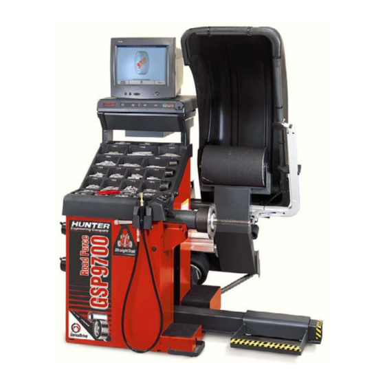
1.3 Equipment Components GSP9712 1. Getting Started • 9 GSP9700 Series Road Force Measurement System Operation... -
Page 18: Standard Balancer Accessories
Pressure Ring 65-72-2 Calibration Weight NOTE: Hunter wheel balancers do not include a standardized set of mounting adaptors. For optional accessories, refer to Wheel Balancer Brochure, Form 3203T. 10 • 1. Getting Started GSP9700 Series Road Force Measurement System Operation... -
Page 19: Operating The Console
1.4 Operating the Console Using Softkeys The “softkeys,” located on the CRT support console directly beneath the CRT, provide operator control of the balancer. The keys are identified as: K1 key K2 key K3 key K4 key Menu shift key Start key Stop key Reset key... -
Page 20: Primary Balancing Display
Primary Balancing Display Using the Control Knob (GSP9712) The control knob is located to the right of the softkeys. The control knob is used to control the on-screen switches and manually input data. The on-screen switches that are available are dependent upon the setup configuration of the balancer. -
Page 21: Using Control Knobs (Gsp9702)
Using Control Knobs (GSP9702) The control knobs are located to the right of the CRT screen. The control knobs are used to control the on-screen switches and to manually input data. The control knobs are identified as the upper, middle, and lower control knobs. The on-screen switches that are available are dependent upon the current mode of the balancer. - Page 22 14 • 1. Getting Started GSP9700 Series Road Force Measurement System Operation...
-
Page 23: Balancing Overview
2. Balancing Overview 2.1 Balancing Modes SmartWeight™ Balancing Technology SmartWeight™ balancing technology is a method of reducing forces on a wheel during balancing. This results in less weight used, and less time balancing tires. SmartWeight is not a procedure. Instead, it measures the forces of side-to-side shimmy and up-and-down shake and computes weight to reduce these forces. -
Page 24: Couple Imbalance
Static balancing alone is a seldom-recommended procedure. For example, a single weight is commonly placed on the inner clip weight position for cosmetic purposes. This is not a recommended practice and usually insures the assembly is not properly dynamically balanced. The assembly may then experience side-to-side imbalance while in motion, causing a shimmy condition and objectionable vibration. -
Page 25: Static And Dynamic Imbalance Sensitivity
Modern “dynamic” balancers spin the wheel in order to measure both the up and down imbalance force and the wobble or shimmy related imbalance (side-to-side). Dynamic balancers direct the operator to place correction weights on the inside and outside correction locations of the rim so that both imbalance shake (static) and imbalance wobble (couple) will be eliminated. -
Page 26: Identifying The Static Balance Weight Plane
2.2 Identifying the Static Balance Weight Plane In “STANDARD BALANCE” mode, using only a clip-on weight, the plane is input as follows: For static balancing, it is recommended that you place half of the correctional weight value on each side of the tire to reduce residual dynamic imbalance. In “MIXED WEIGHTS BALANCE”... -
Page 27: Identifying The Dynamic Balance Weight Planes
2.3 Identifying the Dynamic Balance Weight Planes The balancer must know the location of the two weight circle planes for placement of correction weights on the wheel assembly. Each plane is described by a distance from the balancer and a diameter. STANDARD MIXED WEIGHTS ADHESIVE WEIGHTS... -
Page 28: Smartweight™ Dynamic Weight Planes
In “PATCH BALANCE” mode, using patch weights, left and right planes are input as follows: LEFT DISTANCE DIAMETER RIGHT DISTANCE 2.4 SmartWeight™ Dynamic Weight Planes SmartWeight requires the operator to enter two weight planes. This balancing method will automatically determine if one or both weight planes require a weight to be added. -
Page 29: Mounting Wheels On The Balancer
3. Mounting Wheels on the Balancer 3.1 Mounting the Wheel Using Wheel Lift (Optional) The Wheel Lift is an optional feature on the GSP9700 series balancer. For instructions on mounting the tire/wheel assembly without the optional wheel lift, refer to “Mounting the Wheel,” page 23. Raising the Tire/Wheel Assembly Press the lift control handle “down”... - Page 30 Slide the tire/wheel assembly onto the spindle and center on the mounting cone. Verify that the tire/wheel assembly is centered vertically on the spindle. Refer to “Mounting the Wheel,” page 23. TIRE/WHEEL ASSEMBLY CENTERED VERTICALLY ON SPINDLE SPINDLE Install the clamping cup and wing nut on the spindle shaft against the wheel and secure the entire assembly by firmly tightening the wing nut, while depressing the foot pedal to hold the spindle in place.
-
Page 31: Lowering The Tire/Wheel Assembly
Lowering the Tire/Wheel Assembly Raise the hood. Lift the lift control handle “up” to move the lifting beam and trolley into position to support the tire/wheel assembly. ® Step on the Spindle-Lok /foot pedal of the GSP9700, and then loosen the wing nut that secures the clamping cup. -
Page 32: Mounting Error Detection Features
Mounting Error Detection Features To verify that the tire/wheel assembly is centering, remount the tire/wheel assembly and observe the results. Do any of the following conditions occur? • Weight amount varies excessively • Weight location changes • Runout and road force measurements vary excessively If any of these conditions occur, the centering accuracy of the tire/wheel assembly needs to be verified. - Page 33 ® NOTE: If equipped with optional Spindle-Lok foot pedal, depress and hold down while tightening the wing nut. Holding the shaft locked while tightening the wing nut improves centering accuracy. Slowly roll the wheel toward you during the initial tightening of the wing nut.
-
Page 34: Using Plastic Wheel Mounting Washer
Using Plastic Wheel Mounting Washer The plastic wheel mounting washer, 46-320-2, is used to prevent scratches on wheels where the standard plastic cup and scratch guard cannot be used. The plastic wheel mounting washer can also be used when mounting a wheel with a large offset that is between cone sizes. -
Page 35: Cone/Flange Plate Mounting
Wheels with center bores over 3 9/16 inch diameter require one of the light truck cones. The light truck cones must be mounted from the outside of the wheel. NOTE: When using the light truck cones, the pressure ring is used in place of the clamping cup. -
Page 36: Expandable Collet Mounting
The correct flange adaptor setup is determined by: Measure and set the bolt circle diameter and number of studs to use against the lug holes. Set the number of lugholes as follows: A three-lug wheel uses three studs. A four-lug wheel uses four studs. A five-lug wheel uses five studs. -
Page 37: Spacers
The pressure ring should be used to prevent the wing nut from directly contacting an adaptor or a cone. It will act as a bearing to enable higher clamping forces. Spacers Hub Ring Spacers These light truck spacers are designed to build a larger pocket when using extra large truck cones. -
Page 38: Centeringcheck
® CenteringCheck ® The CenteringCheck feature can be used to inspect each mounting to identify possible centering errors, thus preventing improper measurements from occurring. ® The inner Dataset arm, is used to measure wheel runout which is an indication of mounting repeatability. - Page 39 Position the valve stem at 12 o’clock, and then press “Enter Valve Stem.” After measuring rim runout, you will be prompted to loosen the wheel and re-clamp at one half turn (approximately 180 degrees) from the current position. Place the inner arm against the rim as shown. Press the outer arm button or “Start”...
- Page 40 The GSP9700 will then proceed to the “Balance” screen. If a centering problem is detected, the following screen will appear. The procedure will repeat the re-centering check up to four times and always compare the previous measurement to the next check. If centering is not achieved after four attempts, the following screen will appear.
-
Page 41: On-Vehicle Wheel Mounting Methods
3.3 On-Vehicle Wheel Mounting Methods Hub Centric A hub centric wheel is aligned to the hub by the center bore of the wheel. The vehicle weight rests on the hub bore. The clearance between the hub bore and the hub on a hub centric wheel is between 0.003 and 0.004 of an inch. - Page 42 To verify if the wheel is lug centric: Remove the lug nuts (or bolts) and try to move the wheel up/down and side/side on the hub. A lug centric wheel will display noticeable movement. TIP: When mounting a lug centric wheel to a vehicle, extreme centering care must be taken by ensuring the lug nuts (bolts) are tightened equally, while rotating the wheel.
-
Page 43: Balancing A Wheel
4. Balancing a Wheel 4.1 Balancing Procedures The GSP series balancer offers two primary ways to balance tires: 1. SmartWeight™ balancing technology 2. Traditional balancing technology Both of these methods can balance tires dynamically. The main difference is SmartWeight will reduce the amount of corrective weight and possibly limit the number of steps in a basic wheel balancing situation. - Page 44 Install the tire/wheel assembly as normal. Rim measurements are not required. Lower the hood and spin. If SmartWeight requires correction weights wheel dimensions will be required. Enter the dimensions using the dataset arms. The SmartWeight tire graphs will display red for excessive forces and green for acceptable amounts of force. Prior to measurement the tire graphs will display no color.
-
Page 45: Switching From Smartweight™ To Traditional Dynamic Balancing Modes
Switching from SmartWeight™ to Traditional Dynamic Balancing Modes At any time, SmartWeight can be switched to standard balancing as long as both standard and SmartWeight modes are enabled in setup. On units with a control knob, press the knob until SmartWeight is highlighted. Once highlighted, press and hold the knob till the standard balance icons appear. -
Page 46: Static Balance Mode Reminder For "Dynamic Balance Importance" (Except Patch Balance)
Static Balance Mode Reminder for “Dynamic Balance Importance” (Except Patch Balance) Two reminder pop-up text messages appear on the balance screen dialog box when you first select static mode. The first screen gives the warning: Avoid STATIC single-plane balancing. The second screen suggests: DYNAMIC dual-plane balancing recommended (even for hidden weights). -
Page 47: Selecting Weight Types And Placement Modes
Selecting Weight Types and Placement Modes Press “ ” to change the weight types and placement. The GSP9700 offers Standard Balance, Mixed Weights Balance, Adhesive Weights Balance, and Patch ® Balance for dynamic and static modes. With these four selections, a correction weight can be placed at an infinite number of locations, based upon the choice of the operator. - Page 48 Select either grams or ounces by rotating the control knob and highlighting either “g” or “oz.” Select “DYNAMIC” by rotating the control knob to highlight “ .” Refer to “Dynamic Balancing Selection,” page 37. ® Use both Dataset arms in the UPWARD position at the clip-on weight location to measure the distance, diameter, and rim width dimensions.
-
Page 49: Mixed Weights Balancing Procedure (Combination Of Clip-On & Adhesive Weights)
Attach the weight amount shown on the CRT for the right weight plane to the outer rim of the wheel. ® If necessary, use the right “ ” to split the weight. Refer to “Split Weight Feature,” page 87. Verify balance condition by spinning again with the load roller disabled. Refer to “Load Roller Operation,”... - Page 50 ® Use both Dataset arms in the UPWARD position at the clip-on weight location to measure the distance, diameter, and rim width dimensions. Refer to “Using the Auto ® Dataset Arms,” page 48. Do NOT return the arm to the “home” position. ®...
-
Page 51: Adhesive Weights Balancing Procedure (Adhesive Weights Only)
With the servo enabled, attach the adhesive weight using the weight amount shown for the right weight plane on the CRT. Refer to “Servo-Aided Adhesive Weight Placement,” page 51. If servo is not enabled, BDC placement should be used. Refer to “Manual Weight Position Measurement,”... - Page 52 ® Using the DOWNWARD position, place the inner Dataset arm disk edge to the outermost location for placement of the right edge of the left adhesive weight and ® enter the data by depressing the foot pedal. Refer to “Using the Auto Dataset Arms,”...
-
Page 53: Patch Balance Procedure
With the servo enabled, attach the adhesive weight for the right weight plane using the weight amount shown on the CRT. Refer to “Servo-Aided Adhesive Weight Placement,” page 51. If servo is not enabled, BDC placement should be used. Refer to “Manual Weight Position Measurement,”... - Page 54 Verify that the wheel is clean and free of debris. Remove all previous weights. Mount tire/wheel assembly. Refer to “Mounting the Wheel,” page 23. Press “ .” Use the arrows to select “PATCH BALANCE” and press “OK.” Select either grams or ounces by rotating the control knob and highlighting either “g” or “oz.”...
- Page 55 ® Place outer Dataset arm roller directly over the right mark and enter data by depressing the foot pedal. Close safety hood. Press the green “START” button if “Hood Autostart” is disabled. After wheel stops spinning, raise the safety hood. Press the green “START”...
-
Page 56: Using The Auto Dataset Arms
® 4.2 Using the Auto Dataset Arms ® Auto Dataset arms perform two functions: 1. Input weight position measurements for balancing. 2. Input wheel runout measurements for Road Force™ Measurements. Refer to “Road Force™ Measurement,” page 133. ® Auto Dataset is a faster and more accurate method to take rim measurements than ®... -
Page 57: Measuring Dimensions For Standard Clip-On Weight Balancing
Measuring Dimensions for Standard Clip-on Weight Balancing To measure rim dimensions for clip-on weights, activate the Standard balancing ® mode. Pull the inner Dataset arm away from the weight tray and UPWARD until it is ® touching the top of the wheel inner rim lip. Simultaneously pull the outer Dataset arm out and upward until it is touching the top of the wheel outer rim lip. -
Page 58: Measuring Dimensions For Adhesive Weights Balancing (Tape-On/Tape-On)
Measuring Dimensions for Adhesive Weights Balancing (Tape-on/Tape-on) ® To enter adhesive weight dimensions for the inner plane, pull the inner Dataset away from the weight tray and DOWNWARD, until the roller disk edge is touching the wheel at the right edge of the desired left weight plane location. Depress the foot pedal to enter the dimensional data. -
Page 59: Measuring 20 Inch Or Larger Rims
To extend and lock the arm, loosen the locking screw, and slide the arm to the desired length. If the GSP balancer is not equipped with the extendable two-position arm, an upgrade kit is available through the local Hunter Engineering Company service representative. Servo-Aided Adhesive Weight Placement ®... - Page 60 ® Place the required amount of adhesive weight in the weight clip on the inner Dataset arm and remove the peel-off backing from the adhesive weight. NOTE: The adhesive weight strip should be centered in the weight clip and the peel-off backing should face away from the inner ®...
-
Page 61: Manual Adhesive Weight Placement
Manual Adhesive Weight Placement NOTE: Manual weight placement is not as accurate as servo-aided weight placement. Servo-aided weight placement should be used whenever possible. NOTE: If the servo-aided weight placement is enabled, press the “STOP” button with the hood in the RAISED position to disable. -
Page 62: Rim Runout Measurements
Rim Runout Measurements Rim runout can be measured externally with the tire mounted to the rim bead seats, or the bare rim can be measured separately for more precise measurements. If the assembly does not have a flat faced rim, take the runout measurement. Refer to “Rim Runout External Measurement (Tire and Wheel Assembly),”... - Page 63 ® When Dataset arms are in place, press the outer arm button. The motor will slowly rotate the wheel to measure runout. While the wheel is in motion, gently apply ® upward and inward fingertip pressure on both Dataset arms as shown below: CAUTION: Take care when placing hands to measure rim runout that no part of your hands or body interfere with parts in motion.
-
Page 64: Rim Runout Measurement (Bare Rim)
Rim Runout Measurement (Bare Rim) To measure bare rim runout, remove the tire from the rim. Mount the bare rim on the GSP9700. Select “Measure Rim Runout” from the “Balance” primary screen. Select ® “Measure Bare Rim.” Loosen the outer Dataset arm locking screw by turning it ®... -
Page 65: Primary And Popup Screens
4.3 Primary and Popup Screens Primary Screen Selection Primary screens are selected from either of the two softkey rows of the “Logo” screen of the GSP9700 by pressing the menu shift key. When a primary screen is showing, there is only a single “title bar” across the top of the display. -
Page 66: Balance Primary Screen
® For example, the “CenteringCheck ” popup screen pops up over the “Balance” primary screen. The softkeys change from the primary screen to support the “CenteringCheck®” operation. When the operation is complete or has been cancelled/exited, the popup screen reveals the primary screen from which it appeared. Notice two very important aspects of this scheme: The popup screen does not completely “hide”... - Page 67 The “Set Dimensions” view is displayed in reduced size in the lower left-hand corner. It can be enlarged by pressing “Set Dimensions” or will automatically enlarge if a ® Dataset Arm is moved from home position and triggered to take rim data. “BALANCE VIEW”...
-
Page 68: Load Roller
4.4 Load Roller Load Roller Operation The load roller runs parallel to the tire and applies a perpendicular load on the assembly to take Road Force™ Measurements. It is capable of applying up to 1400 pounds of force. The amount of force placed on the tire is dependent upon the tire’s diameter and stiffness. -
Page 69: Forcematching
4.5 ForceMatching™ ForceMatching™ is a method of aligning the stiffest spot of the radial tire road force first harmonic (once-per-revolution component) with the average low point of the radial rim runout first harmonic to decrease vibration in the wheel assembly. Refer to “Theory of Operation,”... -
Page 70: Forcematching™ Procedures
ForceMatching™ Procedures To correct road force by ForceMatching™: Rotate the tire road force high spot on the wheel to TDC, or with the hood in the raised position and the servo enabled, press “START.” Mark the tire with a piece of chalk or a marker at TDC. If desired, mark the tire with the ForceMatch Code. -
Page 71: Forcematching™ Using Previous Bare Rim Measurement
Use a tire changer and align the tire and rim marks to one another. Refer to the operation instructions for the tire changer in your shop. NOTE: If the wheel assembly can be corrected by ForceMatching™, the results can be viewed prior to removing the assembly from the balancer by selecting “Show After ForceMatching”... -
Page 72: Using Forcematch Codes Feature
Lay the tire down on the floor. Remove the rim from the balancer and set it on top of the tire with the valve stem (“VS”) mark on the tire aligned to the valve stem. With the valve stem and valve stem (“VS”) mark aligned, transfer the road force (“FV”) mark from the rim to the tire and label it “FV.”... -
Page 73: Lateral/Radial Rim High Spot Indicators Feature
Lateral/Radial Rim High Spot Indicators Feature The “Show Lateral High Spot(s)” and “Show Radial High Spot(s)” softkeys are available to select a graphic depiction of the exact radial (blue indicators) or lateral (orange indicators) first harmonic runout high spot locations. The high spots indicated are the high spots of the first harmonic, NOT the T.I.R. -
Page 74: Do's And Don'ts Of Road Force™ Measurement
Do’s and Don’ts of Road Force™ Measurement • Tires may need to be warmed up to remove temporary flat spots prior to testing. • Verify the wheel is centered. • Use the approved adaptors for GSP9700. • Use wing nut provided and it must be tight (do not use quick take up wing nuts). -
Page 75: Quickmatch™ Procedures
QuickMatch™ Procedures To correct loaded runout by QuickMatch™: Rotate the tire loaded runout high spot on the wheel to TDC, or with the hood in the raised position and the servo enabled, press “START.” Mark the tire with a piece of chalk or a marker at TDC. Rotate the rim low spot on the wheel to TDC, or with the hood in the raised position and the servo enabled, press “START.”... -
Page 76: Quickmatch™ Using Previous Bare Rim Measurement
QuickMatch™ Using Previous Bare Rim Measurement If bare rim measurements (refer to “Rim Runout Measurement (Bare Rim),” page 56) have been taken and will be used for QuickMatch™ procedures, it will be necessary to scribe two aligning marks with a marker or chalk on the hub/shaft assembly and the rim. -
Page 77: Lateral/Radial Rim High Spot Indicators Feature
As the wheel assembly is rotated on the spindle, the dial indicator gauges will change to display current information for each dial indicator gauge position. ASSEMBLY LOADED RUNOUT DIAL INDICATOR LATERAL RIM RUNOUT DIAL INDICATORS RADIAL RIM RUNOUT DIAL INDICATORS “Hide Dial Indicators”... -
Page 78: Do's And Don'ts Of Loaded Runout Measurement
• Rim Safety Hump Design ‘Hangs Up’ Tire Bead During Bead Seating: Some types of wheels use a square safety hump that may further inhibit uniform tire bead seating. This further underscores the importance of proper lubrication and bead seating procedures. •... - Page 79 ® Performing a StraightTrak LFM Procedure: Mount the tire/wheel assembly centered on the shaft of the GSP9700. Use care to make sure the wing nut is well tightened. Choose the appropriate balancing procedure for the particular type of rim construction. Check the tire pressure.
- Page 80 After the radial measurements are taken, a lateral force sensor measures forces exerted in the lateral (axial) direction. The drive system then reverses direction and again measures the forces exerted in the lateral (axial) direction. The display provides the operator with RoadForce and imbalance measurements. NOTE: Lateral force is not shown for individual tires, but is stored in memory for use on the Vehicle Plan View screen.
-
Page 81: Disabling Straighttrak
Press “Tire Tags” to number the third tire/wheel assembly. The screen will default to tag 3. Press “OK” to accept tag 3. Refer to “Changing Tag Numbers,” page 75. After tagging the third tire/wheel assembly, the vehicle plan view will reappear. Refer to “Vehicle Plan View,”... -
Page 82: Vehicle Plan View
Vehicle Plan View The vehicle plan view provides a graphic depiction of the information that is gathered by the GSP9700 during a loaded spin. Net Tire Pull Arrow Net pull indicates the direction and the magnitude of pull, due to the tires, that the vehicle will be subject to, if the tire/wheel assemblies are mounted on the vehicle as currently shown on the screen. -
Page 83: Changing Tag Numbers
Changing Tag Numbers The Changing Tag Numbers is the means of identifying each tire/wheel assembly during the StraightTrak® Lateral Force Measurement procedure. When the first tire/wheel assembly is ready to be tagged, the only option will be to tag it as tag 1. The second tire/wheel assembly will default to tag 2, however you may change it to tag 1 by rotating the control knob and then pressing “OK.”... -
Page 84: Show Least Pull
Show Least Pull By pressing “Show Least Pull,” the placement of tire/wheel assemblies on the vehicle that will yield the least net tire pull will be shown. This positioning tries to place the two tire/wheel assemblies on the front axle that have the same amount of pull, but in opposite directions when on the vehicle. -
Page 85: Show Details
Show Details The net tire pull results of all alternate placements appear in a table on the summary printout and can be viewed on-screen by pressing the “Show Details” softkey on the second row of softkeys. The following example shows a case where the “Show Details” softkey can help. With the tire/wheel assemblies positioned as recommended to provide least pull, a vibration could be induced, due to the large amount of radial force in tire/wheel assembly 4. -
Page 86: Inflation Pressure
Inflation Pressure Inflation pressure of each tire, as recorded by the Inflation Station, is displayed on the summary printout. A blank reading indicates that the tire was not measured (inflated or deflated) with the Inflation Station feature. Summary printout will print the tire pressure rounded to the nearest tenth of a pound. The range allowable to fill each tire may vary on the printout by one or two pounds per assembly. -
Page 87: Motor Drive/Servo-Stop
4.9 Motor Drive/Servo-Stop The programmable DC motor drive on the GSP9700 is able to position and hold the tire assembly in position for weight application, apply different amounts of torque, and control the speed and direction of the spindle. If Servo-Stop is enabled, when the “Start” button is pushed with the hood in the raised position, while weights are showing, the motor will automatically rotate the wheel to the next weight plane and hold the assembly in position for weight or ForceMatching Mark application. -
Page 88: Blinding And Rounding
4.13 Blinding and Rounding If traditional balancing method is selected, the balancer can display either an “actual” or “blinded and rounded” amount of imbalance. “Blind” is a tolerance or amount of imbalance required before an imbalance amount is displayed. “Round” allows the balancer to display weight imbalance to a desired increment. -
Page 89: Inflation Station
4.14 Inflation Station Inflation Station provides preset tire pressure setting to ensure accurate Road Force™ Measurement (before and after matching) and safe assemblies for final mounting on the vehicle. The GSP9700 can reduce as well as increase the tire pressure. NOTE: The Inflation Station is a factory installed feature that is not on earlier models of the GSP9700. - Page 90 82 • 4. Balancing a Wheel GSP9700 Series Road Force Measurement System Operation...
-
Page 91: Balancing Features And Options
5. Balancing Features and Options 5.1 SmartWeight™ Balancing Technology SmartWeight™ balancing technology revolutionizes the wheel balancing/vibration correction process. SmartWeight computes balancing correction weights in an effort to eliminate the static forces (up and down shake) and reduce couple forces (side to side shimmy) that are present in the tire and wheel assembly. -
Page 92: Weightsaver™ Wheel Balancing Feature
5.2 WeightSaver™ Wheel Balancing Feature Essentially, SmartWeight sets limits on the forces. WeightSaver adjusts the percentage of these forces to either save weight, or have a more fine-tuned balance. With SmartWeight, and bar graph in the green is within acceptable limits. WeightSaver allows that bar graph window to be changed. -
Page 93: Motor Drive/Servo-Stop
NOTE: Heavier wheel assemblies may require extra lifting to prevent the software limited motor torque control from stopping the rotation of the spindle. Tap the foot pedal twice and the spindle will rotate to install the wing nut to save threading time. -
Page 94: Hood Autostart Feature
5.6 Hood Autostart Feature The balancer can be set to automatically spin the wheel upon hood closure. After a spin, the hood must be lifted completely before the balancer will Autostart again. For safety, the balancer will not Autostart in “Calibration,” “Setup,” “Diagnostics,” if no balancing procedure is selected, or if the Inflation Station hose is out of its “home position.”... -
Page 95: Split Weight Feature
The Inflation Station screen exits automatically when you remove the hose from the valve stem, or if you manually exit via the softkeys. For safety, spinning is prevented for any of the following conditions: When the Inflation Station screen is showing, the hose is not at the storage position, or the hose is pressurized (not disconnected from the valve stem). -
Page 96: Correcting Large Imbalances
Correcting Large Imbalances ® Split Weight can also be used to apply three weights when needed. For example, a large wheel may require 6.75 ounces. Not only is this size unlikely to be in the weight tray, but splitting 6.75 ounces would likewise result in large weights. In this case, apply one-third of the called for weight (in this case 2.25 ounces) at the 6.75 ounce weight location and spin the assembly again. - Page 97 ® Move the inner Dataset arm to the far right weight position, using the DOWNWARD arm position. Enter the data by pressing the foot pedal. ® After inputting weight plane(s), the Split Spoke feature may be initiated by the following steps before returning the arm to the “home” position: ®...
-
Page 98: Re-Entering Similar Wheel After Split Spoke Is Enabled
After wheel comes to a complete stop, raise safety hood. SERVO-AIDED ADHESIVE WEIGHT PLACEMENT SPOKE LOCATION SHOWN POSITIONED AT DATASET ARM HOLDER CONTACT POINT WITH RIM SPOKES OF WHEEL Place left plane weight (if in DYNAMIC mode) per the balance procedure being performed. -
Page 99: Placing Hidden Weight Inside Of Hollow Spokes
® Move the inner Dataset arm to a position centered behind a spoke, using the DOWNWARD arm position to align the spoke location. Enter the data by pressing the foot pedal. Placing Hidden Weight Inside of Hollow Spokes On some wheels, it may be possible to hide all of the right weight plane adhesive weights inside of the hollow spoke. - Page 100 Measure the weight plane diameter manually, using caliper. NOTE: This may need to be done before the wheel is mounted on the GSP9700. Add the measurement from the left weight plane to the desired right weight plane to the distance to the inner rim lip and enter this new dimension manually. Enter the weight plane distance (mm) and diameter (in) manually.
-
Page 101: Matchmaker™ Tire And Wheel Mounting Procedure
5.11 MatchMaker™ Tire and Wheel Mounting Procedure MatchMaker™ tire and wheel mounting procedure allows the operator to match four identical tires on identical rims, to achieve the optimal combination of match mounting. MatchMaker™ provides the operator with on-screen prompts throughout the procedure. -
Page 102: Tires Not Mounted To Rims
Tires Not Mounted to Rims Mount the bare rim on the GSP9700. Measure rim runout by using the outer dataset arm. Refer to “Rim Runout Measurements,” page 54. Position the valve stem at the 12 o’clock position. Press “OK.” Attach an identifying tag to the valve stem of the rim. Repeat the procedure for rims 2, 3, and 4. -
Page 103: Diagnosis Explanation Screen (Limits Disabled)
5.12 Diagnosis Explanation Screen (Limits Disabled) After the Road Force™ Measurement and rim runout measurements have been taken, the GSP9700 will ask whether or not to perform QuickMatch. If any tire or rim assembly component exceeds a non-first harmonic limit, the “Diagnosis Explanation” popup screen will appear to provide a description of the component limit(s) exceeded. -
Page 104: Details Screen
5.14 Details Screen From the “Diagnosis Explanation” screen, you may select to “Show Details.” The “Details” popup screen will present a charted depiction of each measured component and compare the measured data to the limits. Components that are not within limits, but are unlikely to cause vibration are shown in yellow. -
Page 105: Print Summary
From the “Details” popup screen, “Show Runout Plots” may be selected. From this screen, a graphic depiction of the measured data, multiple harmonics, road force, and runout may be viewed. Refer to “Harmonics & T.I.R. Data/Plots,” page 98. 5.15 Print Summary Balance and road force screens have “Print Summary”... -
Page 106: Harmonics & T.i.r. Data/Plots
5.16 Harmonics & T.I.R. Data/Plots A graphic depiction of the data displayed on the “Current Runout & Road Force” popup screen can be viewed by selecting “Show Runout Plots” from the “Details” popup screen. The dotted line represents total indicated reading (T.I.R.), actual movement of the ®... -
Page 107: Tire Data Plots Screen
Tire Data Plots Screen Selecting “Show Tire” will show the tire harmonic and total indicated reading of runout data with the rim contribution removed. The “Tire” lines are color coded to represent a specific value as follows: LINE COLOR DESCRIPTION Violet T.I.R. -
Page 108: Statistics
5.17 Statistics Show Statistics From the “GSP9700 Series Road Force Measurement System” logo screen, “View Statistics” may be selected from the second menu tier. This allows a tally of the spins to be categorized by their road force, radial runout, and lateral runout measurements and viewed or printed for statistical purposes. -
Page 109: Weight Savings
Weight Savings Select from the main logo screen to view a statistical page of balance figures classified by type of weight and rim diameter. The page shows the amount of weight savings, highlighted in blue, using SmartWeight™ balancing technology. The savings are shown in both actual weight and percentage. -
Page 110: Rim Data Plots Screen
Rim Data Plots Screen “Show Rim” may be selected to view rim runout at the inner and outer measured flanges (Refer to “Rim Runout Measurement-Wheel Assembly,” page 54) or bead seats (Refer to “Rim Runout Measurement-Bare Rim,” page 56). The screen defaults to the inner radial rim data. From this screen, you may select to view lateral or radial runout for the inner or outer rim data plot screens. -
Page 111: Equipment Information
Selecting “Identify Software” from the logo screen will display the software version, and all installed features and trademarks. 6.2 Program Cartridge Removal and Installation CAUTION: Only a Hunter authorized service representative should perform this procedure. A static wrist strap should be worn to prevent damage to static sensitive parts. NOTE: Customer settings should be recorded prior to cartridge replacement. -
Page 112: Balancer Set Up
Remove the installed program cartridge from the CRT support console. Insert the new program cartridge into the console. Ensure proper alignment of the cartridge guides with the console alignment guides. Press the cartridge into the data communications board receptacle. Reinstall the access panel and secure with the two Phillips screws previously removed. -
Page 113: Setting Up The Display Language
Setting Up the Display Language Selects the language for displays. Setting Up the Printout Language Selects the language for printouts. ® Setting Up the QuickMatch Feature QuickMatch can be disabled, enabled, or enabled with the toggle key. 6. Equipment Information • 105 GSP9700 Series Road Force Measurement System Operation... -
Page 114: Setting Up The Use Limits Feature
Setting Up the Use Limits Feature This set up choice will allow the operator to enable or disable Runout & Road Force limits. If this is disabled, there will be no Road Force™ failures and many diagnostic messages will not be shown. NOTE: If this is disabled, you will not see “Runout &... -
Page 115: Setting Up The Hood Autostart Feature
Setting Up the Hood Autostart Feature Enables or disables automatically starting the spin upon closing the hood. Setting Up the Servo-Stop/Servo-Push Enables or disables the intelligent DC motor drive to automatically rotate the wheel to the weight or ForceMatch mark positions. Servo-Push may also be enabled, which allows pushing the wheel (approximately 1/8 of a revolution) to cause the intelligent DC motor drive to automatically rotate the wheel to the next weight or ForceMatch Mark positions. -
Page 116: Setting Up The Quick-Thread™ Feature
Setting Up the Quick-Thread™ Feature Enables or disables motor assisted threading of the wing nut. Setting Up the Balance Check Spin Enables or disables the load roller during balance verification spins. When enabled the load roller will automatically disabled as necessary. Setting Up the Weight Units Selects the Weight Units setting for start-up of the GSP9700. -
Page 117: Setting Up The Inflation Station Units
Setting Up the Inflation Station Units Selects English or Metric units for air pressure, or disable the option altogether. Setting Up the Runout Units Selects English or Metric units for displaying runout measurements. Setting Up the Road Force Units Selects the desired units for road force measurement to be displayed on the screen and in printouts. -
Page 118: Setting Up The Prompted Inflation Station
Setting Up the Prompted Inflation Station Enables or disables the program to automatically prompt the user to set tire pressure. Setting Up the Prompted Centering Checks Enables or disables the program to automatically prompt the user to perform a centering check on each wheel. 110 •... -
Page 119: Service Mode Setup And Features
NOTE: Service Mode should only be used by advanced users or Hunter Engineering Company authorized service personnel. By pressing K2 and K3 during boot up or reset twice, the GSP9700 will enter its “Service Mode” enabling the selection of advanced customized settings and hardware specific setup. -
Page 120: Setting The "Lt" Limits
Limits in the Light Truck column are set higher to address the decreased vehicle sensitivity. Hunter Engineering suggests that advanced users consider setting the default specs to a lower value for “P” setting and use the limit title “P” for sensitive applications. -
Page 121: Setting Up The Balance Limits
Setting Up the Balance Limits Enables and sets limits for both standard wheel balancing and SmartWeight balancing. Click on the control knob to change the fields. The current selected field will be highlighted with a description at the bottom of the screen. Main Selections Setting Up the Weight Units Selects the corrective weight units as ounces or grams. -
Page 122: Smartweight™ Options - Setting Up The Force Limits
SmartWeight™ Options - Setting Up the Force Limits NOTE: The force limits values are set to exact default measurements and should not be changed except by qualified personnel for very specific reasons. Force Limits can be adjusted for the up and down static force and the side-to-side couple force. -
Page 123: Setting Up The Console Type
Setting Up the Console Type Selects the three control knob (Model 9700) or single control knob (Model 9712) balancer console. Setting Up the Load Roller Type Selects the correct load roller type, or disables if there is no load roller present. 6. -
Page 124: Calibration And Maintenance
7. Calibration and Maintenance 7.1 Calibration Procedures The “Calibration” primary screen can be selected by pressing “Calibrate” from the “Logo” screen. The “Calibration Procedures” primary screen contains a list box of calibration procedures. As the procedures are individually highlighted by selecting “↑”... -
Page 125: Balancer (3 Spin Procedure)
Balancer (3 Spin Procedure) CAUTION: Remove all cones from shaft prior to beginning calibration procedures. Select “Calibrate” from the “Logo” screen. Select “Balancer” from the “Calibration Procedures” primary screen. Select “Begin Procedure.” Spin 1: Lower hood and press the green “START” button. Spin 2: Lift hood and install calibration weight on the left side of the faceplate in either hole by threading the calibration weight clockwise into the hole. -
Page 126: Inner Dataset ® Arm (Calibration Tool, 221-672-1, Required)
® Inner Dataset Arm (Calibration Tool, 221-672-1, Required) Select “Calibrate” from the “Logo” screen. Select “Inner Dataset” from the “Calibration Procedures” primary screen. Select “Begin Procedure.” Verify that the inner arm is in the “home” position at the top of the weight tray and is not moving. - Page 127 Position the calibration tool parallel to the floor. Tap the foot pedal once or press “OK.” NOTE: To verify that the tool is parallel to the floor, measure from both ends of the calibration tool to the floor. The measurement will be the same at both ends when the tool is parallel to the floor.
- Page 128 ® Place the inner Dataset arm at downward position “4.” Tap the foot pedal once or press “Enter Cal Step.” ® Place the inner Dataset arm at downward position “5.” Tap the foot pedal once or press “Enter Cal Step.” ®...
-
Page 129: Outer Dataset ® Arm (Calibration Tool, 221-672-1, Required)
® Outer Dataset Arm (Calibration Tool, 221-672-1, Required) Select “Calibrate” from the “Logo” screen. Select “Outer Dataset” from the “Calibration Procedures” primary screen. Select “Begin Procedure.” With the hood in the raised position, verify that the outer arm is in the “home” position and that the arm and hood are not moving. - Page 130 ® Place the outer Dataset arm at position “1.” Tap the foot pedal once or press “Enter Cal Step.” ® NOTE: If the outer Dataset arm is unstable while entering any step, a long, high-pitched tone will sound to advise that the step has NOT been entered.
-
Page 131: Load Roller (Calibration Tool, 221-672-1, Required)
® Place the outer Dataset arm ball in the hole for position “4.” Tap the foot pedal once or press “Enter Cal Step.” ® Place the outer Dataset arm at position “5.” Tap the foot pedal once or press “Enter Cal Step.”... - Page 132 Position the calibration tool on the spindle shaft using the spindle shaft slot closest to the end of the tool. Place load roller at position “1.” Tap the foot pedal once or press “Enter Cal Step.” NOTE: If the load roller is unstable while entering any step, a long, high-pitched tone will sound to advise you that the step has NOT been entered.
-
Page 133: Servo-Stop
Position the calibration tool on the spindle shaft using the spindle shaft slot closest to the center of the tool. Place load roller at position “3.” Tap the foot pedal once or press “Enter Cal Step.” Reconnect the load roller return spring. Reconnect the air supply. -
Page 134: Quick Calibration Check Procedure
“End This Test.” Most of the diagnostic data is available for the sole purpose of conveying information to your Hunter Service Representative. Your service representative may request information from these screens to diagnose service concerns. The ability to convey diagnostic data to the representative prior to servicing the GSP9700 will expedite service to your equipment. -
Page 135: Force Sensors
Force Sensors Tests both force sensors and displays samples from the last spin. Rotary Encoders Tests spindle and knob encoders. Displayed data can be changed by turning the spindle and control knob verifying that they are in working order. Keys and Switches Tests keypad and switches. -
Page 136: Changing Ribbon Cartridge (P/N 162-42-2)
Changing Ribbon Cartridge (P/N 162-42-2): Remove the access cover by lifting it off. Slide the printhead to the middle of the printer away from the rollers on the bail. Grasp the cartridge on both sides and lift up. Snap the new cartridge on the printhead plate. (Tilt the back of the cartridge so it slides into the plate, lower the top of the cartridge over the printhead aligning the tabs on either side with the inserts on the printhead plate.) Reinstall the access cover. -
Page 137: Spindle Hub Face And Shaft Maintenance
7.5 Spindle Hub Face and Shaft Maintenance Keep the shaft and wing nut threads clean and lubricated. Lubricate the shaft without contaminating the hub face. Select “Clean Spindle Threads” from the “Balance” primary screen. Run the edge of a rag between the threads while the spindle is slowly turned by the motor drive. - Page 138 130 • 7. Calibration and Maintenance GSP9700 Series Road Force Measurement System Operation...
-
Page 139: Theory Of Operation
8. Theory of Operation 8.1 Harmonic Vibrations A vibration in a tire and rim assembly can be caused by: Imbalance Change in Sidewall Stiffness (Force Variation) Rim Bent/Out-of-Round Tire Out-of-Round Wheel to Axle Mounting Error* Brake Component Wear or Failure* Drivetrain or Engine Component Wear or Failure* Vehicle Component Characteristics* Combination of Some or All Factors... - Page 140 During ForceMatching, the first harmonic vibration of the tire is matched opposite of the first harmonic vibration of the rim to decrease the first harmonic vibration of the assembly. This reduces the vibration felt inside of the vehicle. A vibration that occurs twice for every revolution is defined as a second harmonic vibration.
-
Page 141: Road Force™ Measurement
8.2 Road Force™ Measurement Road Force™ Measurement is new to the automotive service industry. It emulates tire uniformity measurement, which has been measured for years in assembly plants and manufacturing facilities. Road Force™ Measurement can be used to locate and solve uniformity related tire and wheel vibrations. -
Page 142: Tire Radial Force Variation (Uniformity)
Tire Radial Force Variation (Uniformity) To understand the effects of radial force variation, imagine the tire as a collection of springs between the rim and the tire tread. If the “springs” are not of uniform stiffness, a varied force is exerted on the axle as the tire rotates and flexes. This creates a vibration in the vehicle. -
Page 143: Radial Force Variation Vs. Unloaded Run Out
8.4 Radial Force Variation vs. Unloaded Run Out In the manufacturing community, tire uniformity is called radial force variation. The uniformity of most tires manufactured today is measured with a machine in accordance to SAE practice J332. This practice is widely used in the tire industry and describes tire testing equipment and procedures used to measure radial force variation of the tire. -
Page 144: Straighttrak Lateral Force Measurement System
The tests were performed with the vehicle running at different speeds. The first test was at 50 miles per hour and the second test at 70 miles per hour. At 50 MPH: A measured 0.030” (about 30 pounds of road force) of loaded radial runout caused the same amount of vibration as 1.5 ounces (42 grams) of wheel imbalance at 50 mph. -
Page 145: Theory
With the StraightTrak® Lateral Force Measurement (LFM) feature, the Hunter GSP9700 Series Road Force Measurement System can measure the primary lateral forces generated by a rolling tire/wheel assembly. Using the load roller, it applies radial loads of up to 1400 pounds to the tire. -
Page 146: Conicity
Conicity Conicity is the primary lateral tire force measurement that contributes to vehicle pull problems. When combined with other tire and vehicle variables, the vehicle may drive off line if the steering wheel is released. The steering wheel may be straight when the vehicle travels straight, but the driver must exert a force to the wheel to maintain the straight-ahead stability. -
Page 147: Glossary
9. Glossary 9.1 Balancing Terms Amplitude (Magnitude) The amount of force or the intensity of the vibration. Back Coning When the wheel requires the cone to center the wheel on the balancer’s shaft from the backside, primarily due to the chamfer of the wheel. Also referred to as Back-Cone Mounting. - Page 148 Dynamic Balance A procedure that balances the wheel assembly by applying correction weights in two planes so that up and down imbalance and wobble imbalance are eliminated. Electro-Mechanical Ear A device used much like a doctor’s stethoscope and is for noise diagnosis problems only. Force Matching™...
- Page 149 Order The number of disturbances per cycle (rotation). For example, a 1st order vibration occurs once per cycle, and a 2nd order vibration occurs twice per cycle. P, P/SUV, LT “P Tires” refers to passenger tires, “LT Tires” refers to light truck tires, and “P/SUV Tires” refers to P-Rated sport utility vehicle tires.
- Page 150 Road Force™ Variation A change in force exerted on the axle by the tire/wheel assembly while rotating under load. Units of measurement are in pounds, Newton’s, etc. Servo-Stop The ability to locate varying positions of the tire/wheel assemblies and hold the position in place while correctional weights or OE-Matching marks are applied.
Need help?
Do you have a question about the GSP9712 and is the answer not in the manual?
Questions and answers