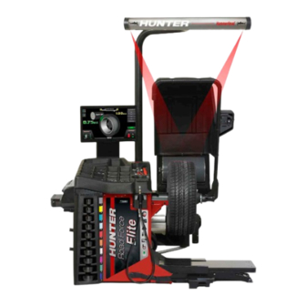
Hunter Road Force Elite GSP9700 Series Operation Instructions Manual
Hide thumbs
Also See for Road Force Elite GSP9700 Series:
- Operation instructions manual (98 pages) ,
- Operating instructions manual (90 pages)
Summary of Contents for Hunter Road Force Elite GSP9700 Series
- Page 1 Form 7118-T 09-21b Supersedes Form 7118-T, 02-21 ® Road Force Elite GSP9700 Series Wheel Balancer Operation Instructions...
-
Page 2: Getting Started
• Do not operate equipment with a damaged cord or • EN/IEC Class 1 Laser Product Certification is shown damaged until examined by a Hunter Service Repre- on Decal 128-1638-2. sentative. • An explanation of FDA compliance standards is •... - Page 3 Figure 1: Right Side View Left Side View Decal 128-391-2-00 cautions that the unit may automati- cally start upon closing of the hood when Hood Autostart is enabled. 128-391-2-00 Figure 5: : Left Side View Back View Figure 2: Front View Decal 128-381-2 warns the operator not to remove the balancer cover and not to use below garage floor level.
- Page 4 A manufacturer’s identification label is on the rear of the a field serviceable part. No maintenance is to be per- balancer. formed on the laser.) Figure 9: Class 1 Laser Warning Wavelength: 650nm. ® HammerHead TDC Laser Precaution The TDC (Top Dead Center) Laser Indicator is a class 2M laser designed to aid in applying clip-on weights.
- Page 5 • Road Force® uses a roller that applies a load to the Main Power Switch tire in order to take road force measurements The main power ON/OFF switch is located on the back of the balancer cabinet. To power the balancer “ON,” press the “I” side of the ON/ OFF switch.
- Page 6 Road Force Elite Main Screen Figure 16: ® Road Force Elite GSP9700 Main Screen Components 1. Tire Stack / Vehicle Plan View Tab 9. Imbalance and Couple Force Display 2. Load Roller 10. Road Force Limits Display 3. Clip Weight Plane 11.
-
Page 7: Inflation Station
Balancing Proce- Hunter Help Video Player On main balancer screen, touch Help → Launch Video dures Player button. Select balancer topic from video menu. Wheel Lift Operation Getting Wheel On Balancer Use two hands to maintain control of the wheel. -
Page 8: Calibration And Maintenance
Calibration & Maintenance Auto Calibration The balancer utilizes an eCal™ automatic calibration procedure. Once the balancer is calibrated at installation time, no further operator input is required. Cleaning the Monitor To maintain a brand new appearance of the display, clean with soft cloth regularly. Do not touch screen with chemicals/ solvents on fingers. - Page 9 Warranty Information Balancing Procedures...
- Page 10 ASE-certified instructor. Fully-equipped training service bays offer hands-on practice using the latest Hunter equipment. Heavy- duty truck alignment facilities offer alignment train- ing on class 8 trucks and semi-trailers. Visit hunter.com/training for more information...


Need help?
Do you have a question about the Road Force Elite GSP9700 Series and is the answer not in the manual?
Questions and answers