Sign In
Upload
Download
Table of Contents
Contents
Add to my manuals
Delete from my manuals
Share
URL of this page:
HTML Link:
Bookmark this page
Add
Manual will be automatically added to "My Manuals"
Print this page
×
Bookmark added
×
Added to my manuals
Manuals
Brands
Hunter Manuals
Wheel Balancers
GSP9200 Touch
Operation instructions manual
Hunter GSP9200 Touch Operation Instructions Manual
Hide thumbs
1
2
Table Of Contents
3
4
5
6
7
8
9
10
11
12
13
14
15
16
17
18
19
20
21
22
23
24
25
26
27
28
29
30
31
32
33
34
35
36
37
38
39
40
41
42
43
44
45
46
47
48
49
50
51
52
53
54
55
56
57
58
59
60
61
62
63
64
65
66
67
68
69
70
71
72
73
74
75
76
77
78
79
80
81
82
83
84
85
86
87
88
page
of
88
Go
/
88
Contents
Table of Contents
Bookmarks
Table of Contents
Table of Contents
Owner Information
Concept and Procedure Training Checklist
1 Getting Started
Introduction
References
For Your Safety
Hazard Definitions
Important Safety Instructions
Save These Instructions
Electrical
Decal Information and Placement
Right Side View
Left Side View
Back View
Specific Precautions/Power Source
Specific Precautions/Bdc Laser Indicator
Specific Precautions/Hammerhead TDC Laser Indicator (Optional)
Turning Power ON/OFF
Push Button Switch
Main Power Switch
Equipment Installation and Service
Equipment Specifications
Explanation of Symbols
Smartweight Touch /GSP9200 Touch Components
Main Screen Components
Operating the Balancer
Main Balance Screen
Main Balance Screen - Error Pop-Ups
Main Balance Screen - Prompt Text
Main Balance Screen - Performing a Spin
Main Balance Screen - Servoing to Position
Main Balance Screen - Smartweight® Buttons
2 Introduction to Balancing
Balance Forces
Balancing Theory - Static Imbalance
Balancing Theory - Couple Imbalance
Smartweight Balancing Technology
Static and Dynamic Imbalance Sensitivity
Smartweight Balancing Technology® Dynamic Weight Planes
Using Smartweight Balancing Technology
Switching from Smartweight Balancing Technology® to Traditional Dynamic Balancing
Switching from Traditional Dynamic Balancing to Traditional Static Balancing
Blinding and Rounding
Enable Performance Mode
Show Savings
3 Balancing Procedures
Mounting a Wheel Using Wheel Lift (Optional)
Raising the Wheel Assembly
Lowering the Wheel Assembly
Mounting the Wheel on the Balancer Spindle Shaft
Installing the Wheel - Typical Scenario
Installing the Wheel Using Quick-Thread® Wheel Clamping
Installing the Wheel Using Auto-Clamp™ Wheel Clamping (Optional)
Centeringcheck® Wheel Centering Feature
Centeringcheck
Centeringcheck® Errors
Balance Mode Centeringcheck
Mounting Error Detection Features
Front / Back Collet Mounting
Using the Plastic Wheel Mounting Spacer
Using the 9-Inch Alloy Wheel Pressure Cup
Front Collet Mounting
Heavy Wheel Centering
Specialized Mounting Conditions
Collet / Flange Plate Mounting
Using the Pressure Ring and Spacers
Pressure Ring
On-Vehicle Wheel Installation Methods
Hub Centric
Lug Centric
Wheel Assembly Selection for Saving Spin Data
Saving Spin Data
Measurement Storage
Print Summary
Balance Modes
Smartweight® Balancing Technology
Dynamic Balancing - Traditional Balancing Mode
Switching from Smartweight Balancing Technology® to Traditional Dynamic Balancing
Static Balancing - Traditional Balancing Mode
Switching from Traditional Dynamic Balancing to Traditional Static Balancing
Blinding and Rounding
Balancing Procedures for Specific Weight Types and Placement Using Truweight
Dimensions Entry
Dimensions Entry - Inner Clip
Dimensions Entry - Inner Tape
Dimensions Entry - Outer Tape
Dimensions Entry - Enter Spoke(S)
Dimensions Entry - Outer Clip
Dimensions Entry - Inner and Outer Clip
Balancing Procedure Using Clip-On Weights
Balancing Procedure Using a Combination of Clip-On & Adhesive (Tape) Weights (Mixed Weights)
Balancing Procedure Using Adhesive (Tape) Weights
Automatic Dataset® Arms Operation
Automatic Weight Position Measurement
Manual Weight Position Measurement
Measuring Dimensions
Blinding and Rounding
Tape Weight Menu
Split Weight
Correcting Large Imbalances
Split Spoke® Feature
BDC Laser Adhesive Weight Locator
Optional Hammerhead TDC Laser Adhesive Weight Locator
Specific Precautions / Hammerhead TDC Laser System
Tpmspecs™ Feature
Hunter Help
Video Player
Launch Help
Printout
Quick-Thread® Wheel Clamping
Auto-Clamping™ Wheel Clamping (Optional)
Motor Drive/Servo-Stop and Spindle-Lok
Motor Drive/Servo-Stop
Spindle-Lok® Feature
Safety Hood Features
Hood Autostart
Loose Hub Detect Feature
4 Equipment Information
Tools
Quick Calibration Check
Set up
Reset All" Button
Specification Database
Volume Control
Date and Time
Support of 3M Tape Weights
Display Language
Print Language
Printer
Print Preview
Printout Paper Size Selection
Selectable Print Destination
Servo-Stop
Rim Dimension Manual Entry
Rim Interior Light
Balance Checkspin
Weight Units
Background Color
Calibration Procedures
Diagnostics
Identify Software
Authorization
Tpms
Clean Threads
Balance Bare Rim
USB Program Flash Drive and Security Key Removal and Installation
5 Calibration and Maintenance
Calibration Procedures
Ecal™ Auto-Calibration
Calibration Check
Diagnostic Tools
Data Acquisition Circuits
Keys and Switches
Ecal
Spindle Encoder
Dataset Arm Sensors
Cleaning the Console
Cleaning the Screen
Safety Instructions
Spindle Hub Face and Shaft
BDC Laser Adhesive Weight Locator Maintenance or Service
Optional Hammerhead TDC Laser Clip-On Weight Locator Maintenance or Service
Mounting Cone Maintenance
6 Glossary
Advertisement
Quick Links
1
Equipment Installation and Service
2
Diagnostics
Download this manual
Form 6555TE-05, 05-14a
Supersedes Form 6555TE-05, 09-12
®
SmartWeight Touch
and GSP9200
Touch Wheel Balancer
Operation Instructions
Software Version 2.0
Copyright © 2012 - 2014 Hunter Engineering Company
Table of
Contents
Previous
Page
Next
Page
1
2
3
4
5
Advertisement
Table of Contents
Need help?
Do you have a question about the GSP9200 Touch and is the answer not in the manual?
Ask a question
Questions and answers
Related Manuals for Hunter GSP9200 Touch
Wheel Balancers Hunter Lite GSP9200 Series Operation Instructions Manual
Computerized lcd balancer with smartweight balancing technology software version 3.3 (83 pages)
Wheel Balancers Hunter GSP9712 Operation Instructions Manual
Road force measurement system with smartweight balancing technology (150 pages)
Wheel Balancers Hunter GSP9720JLR Operation Instructions Manual
Road force measurement system, with smartweight balancing technology software version 3.0 (157 pages)
Wheel Balancers Hunter SmartWeight Touch Operation Instructions Manual
(88 pages)
Wheel Balancers Hunter HD Elite Operation Manual
(52 pages)
Wheel Balancers Hunter HD Elite Operation Instructions Manual
(90 pages)
Wheel Balancers Hunter Road Force Touch GSP9700 Series Installation Instructions Manual
(56 pages)
Wheel Balancers Hunter Road Force Elite GSP9700 Series Operation Instructions Manual
(98 pages)
Wheel Balancers Hunter SmartWeight Pro Operation Manual
(8 pages)
Wheel Balancers Hunter SmartWeight Pro Series Operation Instructions Manual
(98 pages)
Wheel Balancers Hunter DSP9600 Installation Instructions Manual
(18 pages)
Wheel Balancers Hunter Road Force Elite GSP9700 Series Operating Instructions Manual
(90 pages)
Wheel Balancers Hunter Road Force Elite GSP9700 Series Operation Instructions Manual
(10 pages)
Wheel Balancers Hunter SmartWeight Elite Operation Manual
(7 pages)
Wheel Balancers Hunter Lite-A-Line Instruction Manual
Wheel aligner (20 pages)
Summarization of Contents
1. Getting Started
1.1 Introduction
Manual purpose and audience for operating the SmartWeight Touch®/GSP9200 Touch Balancer.
1.2 For Your Safety
Essential safety precautions, hazard definitions, and critical warnings for safe operation of the wheel balancer.
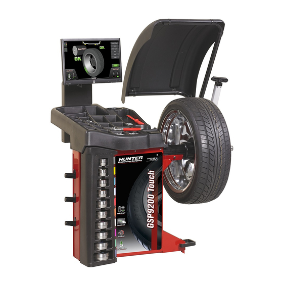
1.3 SmartWeight Touch®/GSP9200 Touch Components
Identification and overview of the main physical components of the SmartWeight Touch® and GSP9200 Touch balancer.
1.4 Main Screen Components
Labels and descriptions of all elements displayed on the balancer's main operational screen.
1.5 Operating the Balancer
Guidance on using the main balance screen, handling error pop-ups, and performing balancing spins.
2. Introduction to Balancing
2.1 Balance Forces
Explanation of static and couple imbalance principles and their impact on wheel balancing.
2.2 SmartWeight Balancing Technology®
Overview of SmartWeight® technology, its benefits, and how it measures forces for accurate balancing.
2.3 SmartWeight Balancing Technology® Dynamic Weight Planes
How SmartWeight® uses two weight planes to effectively address vibration issues in wheel balancing.
2.4 Using SmartWeight Balancing Technology®
Instructions for interpreting the SmartWeight® forces display and executing balancing procedures.
3. Balancing Procedures
3.1 Mounting a Wheel Using Wheel Lift (Optional)
Step-by-step guide for mounting a wheel assembly onto the balancer using the optional wheel lift.
3.2 Mounting the Wheel on the Balancer Spindle Shaft
Procedures for accurately centering and mounting various wheel types onto the balancer spindle.
3.3 CenteringCheck® Wheel Centering Feature
How to use the CenteringCheck® feature to verify wheel mounting accuracy and detect errors.
3.4 Front / Back Collet Mounting
Methods for mounting wheels using collets, covering both front and back collet mounting techniques.
3.5 Specialized Mounting Conditions
Addressing unique wheel mounting scenarios like flange plate use and pressure ring applications.
3.6 On-Vehicle Wheel Installation Methods
Explanation of hub centric vs. lug centric wheel mounting and how to verify them.
3.7 Wheel Assembly Selection for Saving Spin Data
How the balancer tracks and stores wheel assembly data for before/after service comparison.
3.8 Balance Modes
Overview of different balancing modes: SmartWeight®, Dynamic, and Static balancing options.
3.9 Balancing Procedures for Specific Weight Types and Placement using TruWeight™
Detailed steps for applying clip-on, tape, and mixed weights using the TruWeight™ system.
3.10 Automatic Dataset® Arms Operation
Using Dataset® arms for quick and accurate rim measurement and weight position input.
3.11 Blinding and Rounding
Understanding and adjusting settings for displaying imbalance amounts: actual versus blinded/rounded.
3.12 Tape Weight Menu
How to select, split, and apply tape weights using the on-screen menu for improved accuracy.
3.13 Split Spoke® Feature
Utilizing the Split Spoke feature to hide correction weights behind wheel spokes for aesthetic placement.
3.14 BDC Laser Adhesive Weight Locator
Using the BDC laser to assist in precise placement of adhesive weights at bottom dead center.
3.15 Optional HammerHead® TDC Laser Adhesive Weight Locator
Using the HammerHead TDC laser for accurate weight placement at top dead center.
3.16 TPMSpecs™ Feature
Accessing and utilizing TPMS specifications for vehicle wheel service and information.
3.17 Hunter Help
Navigating the integrated help system, including video tutorials and troubleshooting guides.
3.18 Printout
Customizing and printing vehicle service summaries and wheel balance reports.
3.19 Quick-Thread® Wheel Clamping
Using the Quick-Thread feature for fast motor-assisted wing nut installation and removal.
3.20 Motor Drive/Servo-Stop and Spindle-Lok®
Features for precise wheel positioning, motor control, and spindle locking mechanisms.
3.21 Safety Hood Features
Details on the hood autostart function and safety interlocks that control automatic wheel spinning.
3.22 Loose Hub Detect Feature
How the balancer detects loose wheel assemblies and automatically stops rotation for safety.
4. Equipment Information
4.1 Tools
Accessing setup options, calibration checks, and diagnostic tools via the 'Tools' menu.
4.2 USB Program Flash Drive and Security Key Removal and Installation
Procedures for installing and removing USB drives and security keys for software updates.
5. Calibration and Maintenance
5.1 Calibration Procedures
Steps for calibrating balancer systems like datasets, load roller, and performing spin balancer calibration.
5.2 Diagnostic Tools
Utilizing self-diagnostic tools for data acquisition circuits, keys, switches, and eCal™ functionality.
5.3 Cleaning the Console
Guidelines for safely cleaning the balancer's display, console, and spindle area.
5.4 Mounting Cone Maintenance
Proper cleaning and lubrication procedures for mounting cones to ensure correct wheel mounting.
6. Glossary
Table of Contents
Print
Rename the bookmark
Delete bookmark?
Delete from my manuals?
Login
Sign In
OR
Sign in with Facebook
Sign in with Google
Upload manual
Upload from disk
Upload from URL
Need help?
Do you have a question about the GSP9200 Touch and is the answer not in the manual?
Questions and answers