
Related Manuals for Hunter SmartWeight Touch


Summary of Contents for Hunter SmartWeight Touch
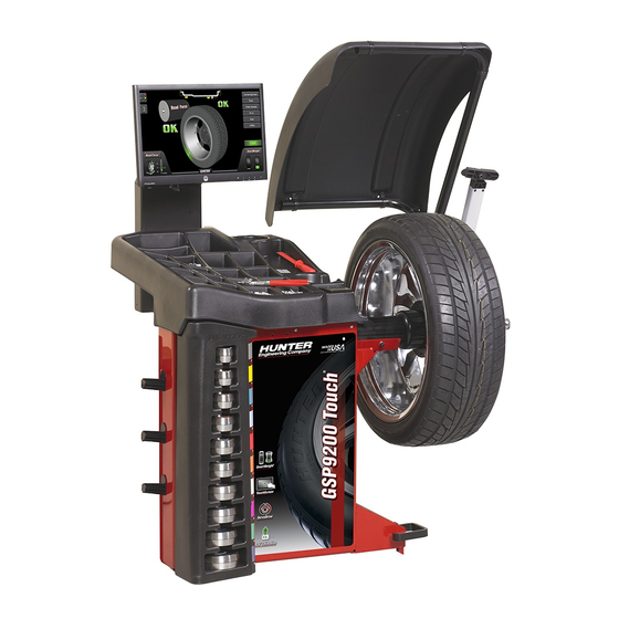
- Page 1 Form 6555TE-05, 05-14a Supersedes Form 6555TE-05, 09-12 ® SmartWeight Touch and GSP9200 Touch Wheel Balancer Operation Instructions Software Version 2.0 Copyright © 2012 - 2014 Hunter Engineering Company...
-
Page 3: Table Of Contents
Explanation of Symbols ............. . 6 1.3 SmartWeight Touch ®... - Page 4 3.17 Hunter Help........
- Page 5 Hood Autostart ..............55 3.22 Loose Hub Detect Feature .
- Page 6 THIS PAGE INTENTIONALLY LEFT BLANK...
-
Page 7: Owner Information
OWNER INFORMATION Model Number Software Version Number Serial Number Date Installed Service and Parts Representative Phone Number Sales Representative Phone Number CONCEPT AND PROCEDURE TRAINING CHECKLIST Trained Declined Safety Precautions Quick-Thread® AutoClamp (optional) Autostart Servo-Stop Maintenance & Calibration Cleaning, Lubrication, and Maintenance of Adaptors, Hub, and Shaft Calibrating the Balancer Calibrating the Load Roller and Dataset Arms Calibrating the Inflation Station... - Page 8 Split Spoke® RimScan TPMS Do’s and Don’ts of Wheel Balancing Adjusting P/SUV/LT Limits Assembly Measurements Applying Previous Wheel Measurements Applying Previous Tire Measurements Wheel Measurement with Dataset Arms Tire Installed Bare Rim Matching Without Rim Runout Individuals and Date Trained: ___________________________________ _____________________________________ ___________________________________...
-
Page 9: Getting Started
1.1 Introduction 1. Getting Started This manual provides operation instructions and information required to operate the SmartWeight Touch®/ GSP9200 Touch Balancer. Read and become familiar with the contents of this manual prior to operating the SmartWeight Touch® or the GSP9200 Touch Balancer. -
Page 10: For Your Safety
Immediate hazards, which will result in severe personal injury or death. To prevent accidents and/or damage to the balancer, use only Hunter SmartWeight Touch® and GSP9200 Touch Balancer recommended accessories. These symbols identify situations that could be detrimental to your safety and/or cause equipment damage. -
Page 11: Save These Instructions
Quick- Thread® shaft rotation. Decal 128-1234-2 gives the maximum wheel diameter ® and maximum wheel weight for the SmartWeight Touch GSP9200 Touch. Decal 128-116-2 warns the operator not to view the laser light with optical instruments. -
Page 12: Left Side View
(Figure 2.)Decal 128-391-2-00 cautions that the unit may Decal 128-381-2 warns the operator not to remove automatically start upon closing of the hood when hood the cover of the SmartWeight Touch/GSP9200 Touch Autostart is enabled. because of the risk of electrical shock and not to use below garage floor level. -
Page 13: Specific Precautions/Bdc Laser Indicator
Push Button Switch to NEMA L15-20P Power Plug Conversion Instructions.” The SmartWeight Touch®/GSP9200 Touch is equipped with a push button power switch located on the left side of the LCD support. Use this switch for normal shut down Specific Precautions/BDC Laser Indicator and restarting procedures. -
Page 14: Equipment Installation And Service
“I” side of the ON/OFF switch. To turn all power the perform installation. balancer “OFF,” press the “O” side of the ON/OFF switch. (Figure 8.) This equipment contains no operator serviceable parts. All repairs must be referred to a qualified Hunter Service Representative. Equipment Specifications Electrical Voltage:... -
Page 15: Smartweight Touch /Gsp9200 Touch Components
® 1.3 SmartWeight Touch /GSP9200 Touch Components TOUCH SCREEN SAFETY HOOD DISPLA Y WEIGHT TRAY OUTER DATASET BULLSEYE™ CENTERING SPINDLE SHAFT SYSTEM COLLET STORAGE INNER DATASET INFLATIO N STATIO N FOOT PEDAL Figure 10. GETTING STARTED... -
Page 16: Main Screen Components
1.4 Main Screen Components Figure 11. 1. Tire Stack / Vehicle Plan View Tab 6. Wheel Assembly Display 2. Wheel Dimensions Tab 7. Start / Stop Button 3. Clip Weight Plane 8. SmartWeight® Menu Button 4. Tape Weight Plane 9. Imbalance and Couple Force Display 5. -
Page 17: Operating The Balancer
1.5 Operating the Balancer Main Balance Screen - Prompt Text When the operator needs more info in a non-error condition, prompting text will appear in the lower portion Main Balance Screen of the screen. Pull-out tabs are on the left for Tire Stack/Vehicle Information (upper tab) and Wheel Dimensions (lower tab). -
Page 18: Main Balance Screen - Servoing To Position
Main Balance Screen – Servoing To Position If servoing is enabled in Setup, the balancer will servo either the inner or outer place weight position to top-dead-center. To servo to the next position, the operator can either touch the “Start” button or touch the corresponding weight amount. -
Page 19: Introduction To Balancing
2. Introduction to 2.1 Balance Forces Balancing Balancing Theory - Static Imbalance As the word static implies, the tire will be balanced when at rest. For example, if an unmoving assembly was centered on a cone and was balanced, it would be statically balanced. -
Page 20: Balancing Theory - Couple Imbalance
A statically imbalanced tire driven for an extended period felt in the steering wheel. Excessive dynamic imbalance may cause “cupping” in the tire’s tread, create vibration, of this type creates a shimmy that transfers through the and adversely effect handling. suspension components to the occupants of the vehicle, especially at higher speeds. -
Page 21: Smartweight Balancing Technology
Dynamic balancers direct the operator to place correction 2.2 SmartWeight Balancing weights on the inside and outside correction locations Technology® of the rim, or a single weight away from the center of the wheel, so that both imbalance shake (static) and SmartWeight Balancing Technology®... -
Page 22: Smartweight Balancing Technology® Dynamic Weight Planes
The traditional “static” and “dynamic” modes are eliminated. The traditional non- The SmartWeight Touch®/GSP9200 Touch balancer round off mode is eliminated. These modes are no longer offers two primary ways to balance tires: necessary with SmartWeight®... -
Page 23: Switching From Smartweight Balancing Technology® To Traditional Dynamic Balancing
Prior to balance spin, the tire graphs will display no color. The SmartWeight® balance force graphs will display red for excessive forces and green for acceptable amounts of force. Figure 30. Figure 33. If the SmartWeight® balancing procedure requires correction weights, wheel dimensions will be required. Install the weights as indicated on the screen using the Enter the dimensions using the Dataset®... -
Page 24: Switching From Traditional Dynamic Balancing To Traditional Static Balancing
SmartWeight Balancing Technology® is the default balancing method and is the most recommended way to accurately balance wheel / tire assemblies. Touch the Disable SmartWeight® button. Figure 40. Figure 36. Touching the static mode icon will switch to static mode. The balancer is now in traditional dynamic balancing mode. -
Page 25: Show Savings
Figure 44. Show Savings Touch the Show Savings button. Figure 45. Figure 50. The SmartWeight® Savings screen will be displayed. Figure 46. Touch the Show Details button to view details of SmartWeight® savings. Figure 47. The Weight Savings screen will be displayed. Figure 48. - Page 26 THIS PAGE INTENTIONALLY LEFT BLANK INTRODUCTION TO BALANCING...
-
Page 27: Balancing Procedures
3. Balancing 3.1 Mounting a Wheel Using Wheel Lift (Optional) Procedures The wheel lift is an optional feature on the SmartWeight Touch®/GSP9200 Touch/GSP9200 Touch series balancer. Raising the Wheel Assembly Slide the appropriate Bullseye™ Centering System collet onto the spindle shaft. Position wheel lift carriage at the end of the wheel lift rail. -
Page 28: Lowering The Wheel Assembly
Roll the wheel assembly onto the wheel lift carriage. Keep the wheel lift carriage in place under the wheel assembly and close the hood. The lifting assembly will automatically lower and park the carriage below. Figure 53. Raise the lift control handle “up” to move the lifting assembly into a position where the wheel assembly can Figure 56. -
Page 29: Mounting The Wheel On The Balancer Spindle Shaft
Slide the carriage with wheel assembly to the end of the 3.2 Mounting the Wheel on the wheel lift rail. Balancer Spindle Shaft Press the lift control handle “down” until the carriage is at Use only cones, collets and accessories that its lowest level. -
Page 30: Installing The Wheel Using Quick-Thread® Wheel Clamping
Position the wheel with the inside surface facing the Slowly roll the wheel towards you while tightening the balancer, centered on the collet. wing nut. This improves accurate wheel centering, since the wheel is allowed to roll up the taper of the collet as opposed to forcing it to slide up the collet. -
Page 31: Installing The Wheel Using Auto-Clamp™ Wheel Clamping (Optional)
Lift the wheel assembly onto the shaft as normal without Heavier wheel assemblies may require extra threading on the wing nut. lifting to prevent the software limited motor torque control from stopping the rotation of the spindle. Tap the foot pedal twice and the spindle will rotate to install the wing nut to save threading time. - Page 32 Install the plastic clamping cup and Auto-Clamp™ device To remove the Auto-Clamp™ assembly, slightly tap the by sliding onto the spindle shaft with the clamping cup Spindle-Lok® foot pedal to release the pneumatically pressed against the wheel. powered spindle. Squeeze the levers on the Auto- Clamp™...
-
Page 33: Centeringcheck® Wheel Centering Feature
3.3 CenteringCheck® Wheel Centering Feature CenteringCheck® CenteringCheck® is an inspection or verification of the wheel’s mount to balance to identify possible centering errors, thus recognizing improper measurements. From the main balance screen, touch the “CenteringCheck” button. Figure 77. Hold down the Spindle-Lok® foot pedal. Loosen the wing nut / AutoClamp™... -
Page 34: Mounting Error Detection Features
Spindle-Lok foot pedal to enter the valve stem The CenteringCheck® procedure will repeat up to four position. times and always compare the previous measurement to the next check. If centering is not achieved after four attempts, the CENTERING FAILURE screen will appear. Figure 80. -
Page 35: Front / Back Collet Mounting
3.4 Front / Back Collet Mounting Install the clamping cup and wing nut / Auto-Clamp™ on the spindle shaft against the wheel and secure the entire assembly as previously described. Collet mounting is one of the most common and reliable ways to mount wheels on balancers. -
Page 36: Using The 9-Inch Alloy Wheel Pressure Cup
Front Collet Mounting LARGE OFFSET RIM Front collet mounting is generally not PLASTIC recommended. It should only be used in SPACER WING NUT instances where traditional backside collet mounting is not possible. SPINDLE This procedure utilizes a collet inserted from the front SHAFT side of the wheel instead of the backside as previously described. -
Page 37: Specialized Mounting Conditions
3.5 Specialized Mounting Conditions because of improper fit, interference, or lack of a center hole. Collet / Flange Plate Mounting A flange plate in many cases adds value because it aids in more effective centering than a collet alone. This Some wheels may be centered using the lugholes and statement is true for many wheels including hub centric center bore with a flange plate and collet. -
Page 38: On-Vehicle Wheel Installation Methods
3.6 On-Vehicle Wheel Installation Lug Centric Methods A lug centric wheel is identified by removing the lug nuts (or bolts) and moving the wheel up, down, and side-to- side. If movement around the hub is apparent, the wheel Hub Centric is centered on the vehicle by the lugs or studs of the axle flange. -
Page 39: Wheel Assembly Selection For Saving Spin Data
Saving Spin Data balanced. (Figure 101.) Saving Spin Data The SmartWeight Touch®/GSP9200 Touch automatically tracks the wheel assembly currently being balanced. The balancer assumes that the technician is working “around the vehicle” by beginning at the LEFT FRONT and working around the vehicle in a clockwise fashion. - Page 40 From this screen, several options may be used to create Select “Recall Next Option Set” to cycle to the next set. custom printouts. Information such as the shop name, customer name, vehicle, etc., can be displayed on the printout. Figure 109. Figure 105.
-
Page 41: Balance Modes
3.8 Balance Modes Touch the SmartWeight® button to display the SmartWeight® menu buttons. SmartWeight® Balancing Technology SmartWeight® Balancing Technology is a method of reducing forces on a wheel during balancing. SmartWeight® is not a procedure. Instead, it measures the forces of side-to-side movement and up-and-down shake and computes weight to reduce these forces. -
Page 42: Static Balancing - Traditional Balancing Mode
Static Balancing – Traditional Balancing Dynamic mode, blinding/rounding is disabled: Mode Enter wheel dimensions before selecting dynamic balancing. If SmartWeight® mode is enabled in setup, the balancer will return to SmartWeight® balancing upon dimension entry. Figure 120. Static balancing provides a less desirable balance than dynamic balancing. -
Page 43: Balancing Procedures For Specific Weight Types And Placement Using Truweight
3.9 Balancing Procedures for Specific Dimensions can be viewed by touching the Dimension button. Weight Types and Placement using TruWeight™ The SmartWeight Touch®/GSP9200 Touch offers both automatic and manual modes for weight placement. Figure 122. Automatic Mode Figure 123. Manual Mode Figure 125. -
Page 44: Dimensions Entry - Outer Tape
Dimensions Entry - Outer Tape Dimensions Entry - Outer Clip Pulling out only the inner Dataset® arm, pointing Pulling out only the outer Dataset® arm after already it down and pressing on the foot pedal records the measuring an inner clip dimension signals to the balancer first dimension. - Page 45 Use both Dataset® arms in the UPWARD position at the clip-on weight location to measure the distance, diameter, The SmartWeight Touch®/GSP9200 Touch will find the and rim width dimensions. top-dead-center (TDC) for the first weight plane if “Servo- Stop” is enabled. “Servo-Stop” will hold the wheel in the TDC position while the weight is applied.
-
Page 46: Balancing Procedure Using A Combination Of Clip-On & Adhesive (Tape) Weights (Mixed Weights)
Left and right weight plane displays should show “OK” after the check spin. Figure 139. The SmartWeight Touch®/GSP9200 Touch will rotate the wheel to TDC for the next weight plane. The view of the wheel will also change to the next plane view and the weight amount for the next plane will be displayed in green. - Page 47 Verify that the wheel is clean and free of debris. Remove all previous weights. Mount tire/wheel assembly. INNER Use the inner Dataset® arm in the UPWARD position DATASET at the clip-on weight location to measure the distance, diameter, and rim width dimensions. Figure 148.
- Page 48 The SmartWeight Touch®/GSP9200 Touch will find the The SmartWeight Touch®/GSP9200 Touch Servo- top-dead-center (TDC) for the first weight plane if “Servo- Activated Laser automatically locates BDC to aid in fast Stop” is enabled. “Servo-Stop” will hold the wheel in the adhesive weight positioning.
-
Page 49: Balancing Procedure Using Adhesive (Tape) Weights
Balancing Procedure Using Adhesive (Tape) Weights Figure 156. INNER DATASET LEFT PLANE Figure 159. Do NOT return the inner Dataset® arm to the “home” LEFT RIGHT DIAMETER DIAMETER position. Using the DOWNWARD position, move the inner Dataset® arm disk edge to the location for placement of the right edge of the adhesive weight on the right weight TAPE plane and enter data by depressing the foot pedal. - Page 50 If the Split Spoke® feature of hiding weights behind The SmartWeight Touch®/GSP9200 Touch Servo- spokes is to be used, position the Dataset® arm disk in Activated Laser automatically locates BDC to aid in fast the center of a spoke and tap the foot pedal.
-
Page 51: Automatic Dataset® Arms Operation
3.10 Automatic Dataset® Arms Operation Auto Dataset® arms are a faster and more accurate method to take rim measurements than traditional methods. Auto Dataset® arms are used to input rim distance, rim width, and weight plane location automatically. The Dataset® arms of the SmartWeight Touch®/GSP9200 Touch are positioned on the weight plane and data is entered by depressing the foot pedal. -
Page 52: Manual Weight Position Measurement
Automatic is the default setting, automatically choosing the correct type of weights and locations determined by Dynamic mode, blinding/rounding is disabled: the placement of the Dataset® arms. Hunter Engineering Company recommends using the inner and outer Dataset® arms to enter dimensions (Automatic). -
Page 53: Tape Weight Menu
3.12 Tape Weight Menu calculations. The ability to “tell” the balancer what you are using and doing avoids time consuming weight chasing. By touching a weight on the wheel, such as the strips of The weight menu won’t always provide a choice using weight shown below, a weight style menu will appear. -
Page 54: Correcting Large Imbalances
To return to the single weight, touch “Split the Weight” 3.13 Split Spoke® Feature repeatedly until the weights become larger than the single weight and return to the un-split weight. When in either mixed weight or adhesive weight modes, (dynamic or static), correction weights can be hidden behind the spokes of a wheel. -
Page 55: Bdc Laser Adhesive Weight Locator
® 3.14 BDC Laser Adhesive Weight 3.15 Optional HammerHead Locator Laser Adhesive Weight Locator The Servo-Activated Laser automatically locates BDC to The balancer will find the TDC for the left or right weight aid in fast adhesive weight positioning. plane if “Servo-Stop” is enabled. “Servo-Stop” will hold the wheel in the TDC position while the servo-activated During the mixed weights and adhesive weights laser automatically locates TDC to aid in fast clip-on... -
Page 56: Specific Precautions / Hammerhead Tdc Laser System
3.16 TPMSpecs™ Feature Laser System TPMS specifications can also be found on Use caution in regard to reflective materials around the Hunter Aligners (with WinAlign 11.0 and greater) laser and never look into the laser beam and online at UnderCarInfo.NET (subscription service). - Page 57 The main TPMSpecs® screen is displayed. Select the The “AT A GLANCE” overview starts each vehicle TPMS make, model and specifics of the vehicle being serviced. specification. The first image shows the type of TPMS sensor on the vehicle. The following three images show the requirements for servicing the wheel: process, scan tool and OEM scanner.
-
Page 58: Hunter Help
Touch the “print” button to print the current page. 3.17 Hunter Help Video Player The Video Player feature provides tips and procedures for using the SmartWeight Touch ®/GSP9200 Touch GSP9700. To access the Video Player: Figure 192. Touch “X” to return to the balancer screen. -
Page 59: Launch Help
Stop the video by touching the “stop” button. The Hunter Help feature provides tips and procedures for Hunter balancers and tire changers. It also provides a Rolling Smooth Sample Quiz. Additional content will be added to the Hunter Help files and can be updated as it becomes available. - Page 60 The Main Menu of Hunter Help is displayed. Select the Scroll up or down by dragging the scroll bar, or touching item to view by touching the selection. the “up” and “down” arrows on the right side of the screen.
-
Page 61: Printout
3.18 Printout Touching the “Print” button will allow the operator to print summary information. Figure 216. Touching the “Vehicle Summary” button opens the Vehicle Summary screen. Figure 220. Touching in any text field will launch the on-screen keyboard. Use the on-screen keyboard to type in the desired fields. -
Page 62: Quick-Thread® Wheel Clamping
• If the balancer is in “Diagnostics,” “Setup,” or feature that allows motor assisted threading for fast “Calibration.” installation and removal of the SmartWeight Touch®/ GSP9200 Touch wing nut. • If either Dataset® arm is out of its “home position”... -
Page 63: Motor Drive/Servo-Stop And Spindle-Lok
3.20 Motor Drive/Servo-Stop and 3.21 Safety Hood Features Spindle-Lok® Hood Autostart Motor Drive/Servo-Stop The balancer can be set to automatically spin the wheel upon hood closure. After a spin, the hood must be raised The intelligent DC motor drive on the SmartWeight™ is completely before the balancer will Autostart again. -
Page 64: Loose Hub Detect Feature
3.22 Loose Hub Detect Feature When the SmartWeightTouch® senses that the wheel is loose, it will automatically stop the spin. Secure the tire/ wheel assembly before proceeding. If the wing nut appears to be tight, remove the wing nut and then clean and lubricate the spindle threads. -
Page 65: Equipment Information
4. Equipment 4.1 Tools The Tools button contains equipment information and set Information up options. Quick Calibration Check Quick Calibration Check allows the operator to check balancer calibration. From the main balance screen, touch the “Tools” button. Figure 224. Touch the “Quick Calibration Check” button. Figure 225. -
Page 66: Reset All" Button
From the main balance screen, touch the “Tools” button. When the selection is made, touch “OK” to save or “Cancel” to abandon. Figure 228. Touch the “Advanced” button. Figure 229. Touch the “Set Up” button. Figure 234. To scroll up or down in the list of items, either press the “Up”... -
Page 67: Specification Database
Figure 239. Figure 242. TPMS specification information can be accessed by Specification Database touching the “View TPMS Info” button. The specification database can be accessed by two different methods. Touch the specification database tab button or touch the text that says “No Vehicle Selected.” Figure 243. -
Page 68: Date And Time
Figure 245. Figure 248. Date and Time Date and time can be set by user. There is also support Support of 3M Tape Weights for international date format (DD/MM/YYYY). The ability to use 3M tape weights is now available. Note: From the set up screen, touch “Set Date and Time”. -
Page 69: Display Language
When prompted for adding balance weight, touch the weight icon on the rim. The 3M tape weights will show up as a selection. Touch the 3M tape weight to use it. Figure 251. The screen will display a list of available set up options. -
Page 70: Printout Paper Size Selection
Printout Paper Size Selection Selects the size of paper for printouts. Selectable Print Destination From any printable screen or report, there is now an option to print to multiple destinations. For example, if there is a printer attached to the balancer and a thumb drive is plugged into a USB port, the operator is given a choice of where the print job should go. -
Page 71: Rim Interior Light
Use a tape measure to obtain the outer rim dimension. Rim Interior Light ® When the inner Dataset is rotated downward, the rim Touch the box and use the keypad to enter the interior light activates. This is useful for inspection, dimension. -
Page 72: Calibration Procedures
Calibration Procedures Using calibration procedures, the operator can calibrate the following systems: • Inner Dataset • Outer Dataset The operator can also perform a 3 Spin Balancer Calibration and check calibration of any of the systems. From the main balance screen, touch the “Tools” button. Figure 269. -
Page 73: Identify Software
Touch the “Advanced” button. Figure 280. Touch the “Identify Software” button. Figure 281. Touch the “Show Authorization” button. Figure 274. Identify Software Figure 282. From the main balance screen, touch the “Tools” button. The Electronic Key Authorization screen is displayed. Figure 275. - Page 74 The main TPMSpecs® screen is displayed. Select the The “AT A GLANCE” overview starts each vehicle TPMS make, model and specifics of the vehicle being serviced. specification. The first image shows the type of TPMS sensor on the vehicle. The following three images show the requirements for servicing the wheel: process, scan tool and OEM scanner.
-
Page 75: Clean Threads
Touch the “print” button to print the current page. Figure 293. Touch “X” to return to the balancer screen. Figure 298. Balance Bare Rim From the main balance screen, touch the “Tools” button. Figure 294. Clean Threads Figure 299. From the main balance screen, touch the “Tools” button. Touch the “Balance Bare Rim”... -
Page 76: Usb Program Flash Drive And Security Key Removal And Installation
4.2 USB Program Flash Drive and Security Key Removal and Installation Turn power to balancer OFF. Remove the rear cover from the support assembly for the LCD display by removing the six screws. Set the rear cover and attaching hardware aside. Insert the USB program flash drive(s) into open USB sockets on the Mini-ITX/Atom Motherboard. -
Page 77: Calibration And Maintenance
5. Calibration and 5.1 Calibration Procedures Maintenance eCal™ Auto-Calibration The SmartWeight Touch®/GSP9200 Touch utilizes eCal™ automatic calibration. Once the balancer is calibrated at installation time, no further operator input is required. Calibration Procedures Using calibration procedures, the operator can calibrate the following systems: •... -
Page 78: Calibration Check
Select the desired calibration procedure and follow the on-screen instructions. Figure 314. Figure 310. Calibration Check A quick calibration check can be performed on the balancer using a calibration weight. From the main balance screen, touch the “Tools” button. Figure 311. Touch the “Quick Calibration Check”... -
Page 79: Diagnostic Tools
Figure 318. Most of the diagnostic data is for the sole purpose of conveying information to the Hunter Service Figure 322. Representative. The service representative may request information from these screens to diagnose service eCal™... -
Page 80: Spindle Encoder
The eCal™ screen is displayed. The Test Spindle Encoder screen is displayed. Figure 324. Figure 329. Touch the “eCal History” button. Dataset Arm Sensors Touch the “More...” button. Figure 325. Choose which eCal history timeframe to view. The eCal Figure 330. history is displayed. -
Page 81: Cleaning The Console
5.3 Cleaning the Console Spindle Hub Face and Shaft Keep the shaft and wing nut threads clean and lubricated. When cleaning the console, use window cleaning solution Lubricate the shaft without contaminating the hub face. to wipe off the display console and cabinet. Do not spray Run the edge of a rag between the threads while the window cleaning solution directly onto LCD. -
Page 82: Optional Hammerhead Tdc Laser Clip-On Weight Locator Maintenance Or Service
® Optional HammerHead TDC Laser Clip-On 5.4 Mounting Cone Maintenance Weight Locator Maintenance or Service Keep the mounting cones clean and lubricated. Lubricate with a coating of light lubricant with Teflon® such as Use of controls or adjustments or Super Lube® by Loctite. performance of procedures other than those specified herein may result in Do not use cones in any way that is not described in... -
Page 83: Glossary
If loaded with the SmartWeight Touch® load roller or driven, the position Forced Vibration of the bead may optimize or always remain seated improperly, unless the tire is demounted, lubricated, and Vibrates when energy is applied. - Page 84 A specifically designed wheel/tire assembly that does not use the traditional rim lip/bead design. PAX assemblies Inflation Station require adhesive or patch balancing. A feature on models of the SmartWeight Touch® that automatically inflates or deflates tires to a predetermined Phase air pressure.
- Page 85 Resonance Spindle-Lok® The point where a vibrating component’s frequency A feature that locks the spindle in place by depressing the matches the natural frequency of another component. foot pedal. Responding Component Split Weight® The noticeable component that is vibrating. Feature designed to reduce single heavy amounts of weight by dispersing the corrective weight over a wider area.
- Page 86 Wheel Diameter Dimension measured on the inside of the rim at the bead seats. Wheel Offset The measured distance between the mounting face of the wheel and the centerline of the rim. Wheel Width Dimension measured on the inside of the rim between the bead seats.
- Page 87 THIS PAGE INTENTIONALLY LEFT BLANK...
- Page 88 www.Hunter.com...