
Related Manuals for Hunter HD Elite


Summary of Contents for Hunter HD Elite
- Page 1 HD Elite Wheel Balancer OPERATIONS MANUAL Form: BM08069-00 Publication date 03/20/2024 Supersedes 11-23...
-
Page 2: Table Of Contents
1.6. Power Switch ............................7 1.7. Equipment Specifications ........................... 8 1.7.1. Explanation of Symbols ........................8 1.8. HD Elite® Main Screen Components ......................9 1.9. HD Elite Components ..........................10 2. Operating the Balancer ............................11 3. Balancing Procedures ............................14 3.1. -
Page 3: Getting Started
HD Elite Balancer. The owner of the HD Elite Balancer is solely responsible for arranging technical training. The HD Elite Balancer is to be operated only by qualified trained technicians.Maintaining records of personnel trained is solely the responsibility of the owner and management. -
Page 4: Electrical
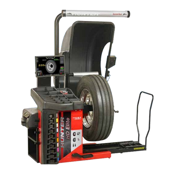
Never reach under the hood while the balancer is performing a run out measurement or balance spin. 1.3. Electrical The Hunter HD Elite Balancer is manufactured to operate at a specific voltage and amperage rating. Make sure that the appropriate electrical supply circuit is of the same voltage and amperage ratings as marked on the balancer. - Page 5 HD Elite Wheel Balancer FRONT VIEW FDA standards for Class 2M laser compliance are shown on Decal HD Elite 28-HD, Elite HD, and Elite 55-2 (for TDC Units ). The Class 2M laser apertures are located at either end of the TDC header.
-
Page 6: Precautions
HD Elite Wheel Balancer Decal HD Elite warns the operator not to remove the cover of the HD Elite because of the risk of electrical shock and not to use below garage floor level. ETL certification standards are outlined on Decal HD Elite. Additionally, users are cautioned not to use the balancer below garage floor level. -
Page 7: Power Switch
Form 5350-T OPTICAL SCAN LASER The Optical Scan Laser is a class HD Elite laser designed to measure the profile of wheel assemblies. The laser is not a field serviceable part. No maintenance is to be performed on the laser. -
Page 8: Equipment Specifications
1.7. Equipment Specifications Only a Hunter Factory-Authorized Representative should perform installation. This equipment contains no operator serviceable parts. All maintenance and repairs must be referred to a qualified Hunter Service Representative. Table 1. Equipment Specifications Electrical... -
Page 9: Hd Elite® Main Screen Components
HD Elite Wheel Balancer Not intended for connection to public network 1.8. HD Elite® Main Screen Components Table 2. Main Component Legend 1. Tire Stack / Vehicle Plan View Tab 9. Imbalance and Couple Force Display 2. Load Roller (if installed) 10. -
Page 10: Hd Elite Components
HD Elite Wheel Balancer 1.9. HD Elite Components Page 10 of 51... -
Page 11: Operating The Balancer
HD Elite Wheel Balancer 2. Operating the Balancer Main Balance Screen Pull-out tabs are on the left for Tire Stack/Vehicle Information (upper tab) and Wheel Dimensions (lower tab). Buttons along the right side allow navigation to other screens and activities. Buttons in the lower left and right portions of the screen allow navigation to Force Match®and SmartWeight®... - Page 12 HD Elite Wheel Balancer Main Balance Screen – Enable and Disable Load Roller To enable or disable the load roller in the main balance screen, touch the load roller on the screen to cycle through all available options. Main Balance Screen – Inflation Station When the operator attempts a loaded balance spin, and if “Prompted Inflation Station”...
- Page 13 HD Elite Wheel Balancer Main Balance Screen – Servoing To Position If servoing is enabled in Setup, the balancer will servo either the inner or outer place weight position to top dead-center. To servo to the next position, the operator can either touch the “Servo”...
-
Page 14: Balancing Procedures
HD Elite Wheel Balancer 3. Balancing Procedures 3.1. Wheel Lift Operation Raising the Wheel Assembly CAUTION When operating the wheel lift, make sure to maintain two-handed control of the wheel assembly. Slide the appropriate Bullseye™ Centering System collet onto the spindle shaft. - Page 15 HD Elite Wheel Balancer Collet mounting is one of the most common and reliable ways to mount wheels on balancers. The Bullseye® Centering System is a set of collets that provides wheel centering coverage for most passenger cars and light trucks.
-
Page 16: Specialized Mounting Conditions
HD Elite Wheel Balancer Front Collet Mounting NOTICE Front collet mounting is generally not recommended. It should only be used in instances where traditional backside collet mounting is not possible. This procedure utilizes a collet inserted from the front side of the wheel instead of the backside as previously described. - Page 17 HD Elite Wheel Balancer To remove, push down on silver latch button and pull up on the pin at the same time. If more than one intersecting slot is present, use the one located in the center of the slot.
- Page 18 HD Elite Wheel Balancer WARNING NOTICE DO NOT pry or hammer stuck For Ford 7 X 150 mm lug pattern, align the index pin pins from adjustable flange to the 150 mm mark and insert the remaining six pins, plate.
- Page 19 HD Elite Wheel Balancer WARNING The pin pattern on the flange plate must be adjusted to the diameter of the lug pattern of the wheel, prior to mounting the flange plate to the balancer. The pins will NOT self adjust as the wing nut is tightened. If the pins are not properly adjusted to the lug pattern, the pin tabs, adjustable flange plate or wheel may be damaged.
-
Page 20: Wheel Assembly Selection For Saving Spin Data
MEASUREMENT STORAGE The HD Elite® automatically tracks the wheel assemblies as they are balanced. As the wheel assemblies are balanced, their status can be viewed as they would appear on the vehicle currently being serviced. Select the VirtualView® button to expand the VirtualView®... - Page 21 HD Elite Wheel Balancer Dynamic balancing will always display two weight planes. It provides a more complete balance than static balancing. Dynamic balancing should be selected whenever possible to minimize vehicle vibration. Switching from SmartWeight Balancing Technology® to Traditional Dynamic Balancing At any time, SmartWeight Balancing Technology®...
-
Page 22: Motor Drive / Servo-Stop And Spindle-Lok
Because of the software limited torque control, you must loosen the wing nut before you remove it. MOTOR DRIVE / SERVO-STOP The intelligent DC motor drive on the HD Elite Balancer is able to position and hold the tire assembly in position for weight application, apply different amounts of torque, and control the speed and direction of the spindle. -
Page 23: Safety Hood Features
HD Elite Wheel Balancer WARNING Using the Spindle-Lok® to stop a spinning wheel may result in personal injury or damage to the balancer. 3.7. Safety Hood Features Hood Autostart The balancer can be set to automatically spin the wheel upon hood closure. After a spin, the hood must be raised completely before the balancer will Autostart again. -
Page 24: Balancing Procedure Using Clip-On Weights
NOTICE If Auto Hood is enabled, the hood will raise automatically. The HD Elite® will find the top-dead-center (TDC) for the first weight plane if “Servo-Stop” is enabled. “Servo-Stop” will hold the wheel in the TDC position while the weight is applied. - Page 25 Select the green “START” button with the safety hood in the raised position. The HD Elite® will rotate the wheel to TDC for the next weight plane. The view of the wheel will also change to the next plane view and the weight amount for the next plane will be displayed in green.
-
Page 26: Balancing Procedures Using A Combo Of Clip-On & Adhesive (Tape) Weights (Mixed Weights)
After wheel comes to a complete stop, raise safety hood. The HD Elite® will find the top-dead center (TDC) for the first weight plane if “Servo-Stop” is enabled. “Servo-Stop” will hold the wheel in the TDC position while the weight is applied. -
Page 27: Balancing Procedure Using Adhesive (Tape) Weights
NOTICE If Auto Hood is enabled, the hood will raise automatically. The HD Elite® Servo-Activated Laser automatically locates adhesive weight positioning. The laser weight locator automatically displays a vivid line after a wheel has been spun. The laser turns off when the wheel is spun again. -
Page 28: Rim Dimension Manual Entry
HD Elite Wheel Balancer CAUTION Use of controls or adjustments or performance of procedures other than those specified herein may result in hazardous radiation exposure. With the servo enabled, attach the adhesive weight using the weight amount shown for the left weight plane on the screen. -
Page 29: Rim Dimension Manual Entry - Clip/Clip
HD Elite Wheel Balancer Press the Manual Entry button in the upper right-hand portion of the screen. Use a tape measure to measure the lengths called out on-screen. Touch each box and enter the appropriate measured dimensions. When finished, press OK to end manual dimension entry. -
Page 30: Blinding And Rounding
HD Elite Wheel Balancer Press the Manual Entry button in the upper right-hand portion of the screen. Use a tape measure to measure the lengths called out on-screen. Touch each box and enter the appropriate measured dimensions. When finished, press OK to end manual dimension entry. -
Page 31: Tape Weight Menu & Split Spoke Feature
HD Elite Wheel Balancer Dynamic mode, blinding/rounding is disabled: Static mode, blinding/rounding is enabled: 3.9.4. Tape Weight Menu & Split Spoke Feature Tape Weight Menu By touching a weight on the wheel, such as the strips of weight shown below, a weight style menu will appear. This offers the ability to change to another style of tape weight and/or split the weight. -
Page 32: Tpmspecs™ Feature & Hunter Help
The unit should never be opened or modified. 3.11. TPMSpecs™ Feature & Hunter Help TPMSpecs™ Feature NOTICE TPMS specifications can also be found on Hunter Aligners (with WinAlign 11.0 and greater) and online at UnderCarInfo.NET (subscription service). Page 32 of 51... - Page 33 Touch the “print” button to print the current page. Touch “X” to return to the balancer screen. Hunter Help - Video Player The Video Player feature provides tips and procedures for using the HD Elite®. To access the Video Player: From the main balance screen, touch the “Help” > “Launch Video Player” buttons.
- Page 34 The Hunter Help feature provides tips and procedures for Hunter balancers and tire changers. It also provides a Rolling Smooth Sample Quiz. Additional content will be added to the Hunter Help files and can be updated as it becomes available.
-
Page 35: Smartweight® Balancing
This eliminates “blinded” static single plane balancing, which alone may not be sufficient to solve couple vibration issues. The HD Elite® balancer offers two primary ways to... -
Page 36: Using Smartweight® Balancing Technology
HD Elite Wheel Balancer SmartWeight® Balancing Technology Traditional balancing technology Both of these methods can balance tires dynamically. The main difference being that SmartWeight® will reduce the amount of corrective weight in a basic wheel balancing situation and automatically optimize static force reduction and single plane weight placement. -
Page 37: Switching From Smartweight® Balancing To Traditional Dynamic Balancing
HD Elite Wheel Balancer If the SmartWeight® balancing procedure requires correction weights, wheel dimensions will be required. Close the hood and perform a spin. After the spin is complete, the screen will display the amount and location of corrective weight necessary. - Page 38 HD Elite Wheel Balancer Dynamic mode is selected: Touch the static mode icon for static mode balancing. Blinding and Rounding In non-SmartWeight® mode, the balancer can display either an “actual” or “blinded and rounded” amount of imbalance. Touching the magnifying glass icon next to the dynamic or static icons will toggle blinding and rounding on or off.
-
Page 39: Forcematching Measurement® Procedures
NOTICE It is important that the air pressure of the tire is set to specifications prior to using the HD Elite Measurement® system. Incorrect tire pressure will affect the results. If the HD® Elite is equipped with the Inflation Station feature, the tire can be easily set to the specified air pressure. - Page 40 HD Elite Wheel Balancer When the HD Elite performs a spin with the load ForceMatch® - Display of Data roller enabled, it measures the road force of the wheel assembly. ForceMatch® is enabled on every Road Force® spin. NOTICE It is important that the air pressure of the tire is set to specifications prior to using the Road Force Measurement®...
-
Page 41: Match Codes
5.2.1. Match Codes Match codes can be used to obtain optimal ForceMatch® results between multiple tire and rim assemblies. They are especially helpful when high ForceMatch® values are encountered. The former Hunter MatchMaker® feature used a similar system. When a tire and rim assembly are balanced using ForceMatch®, a number (match code) is displayed... - Page 42 HD Elite Wheel Balancer When the tire and rim assembly is rotated to the low spot on the rim, a number (match code) is displayed above the tire. This is the value of the low spot on the rim. It is an arbitrary number.
-
Page 43: Encountering Forcematch® Prediction Errors
HD Elite Wheel Balancer Position the valve stem at 12:00 and touch “Enter Mark the tire with a piece of chalk or a marker with a “V” Valve Stem”. opposite the valve stem as indicated. Touch “OK” or tap the foot pedal when completed. -
Page 44: Do's And Don'ts Of Road Force Measurement
5.3. ForceMatch & SmartWeight Savings Savings generated through prevented comebacks using the HD Elite® roller can also be viewed. Touch the ForceMatch® button. In the ForceMatch® menu, touch the Show Savings button. The ForceMatch and SmartWeight® savings screen will be displayed. -
Page 45: Optional Balancer Procedures
HD Elite Wheel Balancer 6. Optional Balancer Procedures 6.1. Tools The Tools button contains equipment information and set up options. Set Up The “Set Up” screen contains a list box of balancer set up items. Select the item you wish to set up and follow the on screen prompts. - Page 46 HD Elite Wheel Balancer Scroll up or down by dragging the scroll bar, or touching the “up” and “down” arrows on the right side of the screen. Touch the “Home” button to return to the main TPMSpecs® Menu. Touch the “arrows” to navigate backward or forward.
-
Page 47: Maintenance
HD Elite Wheel Balancer 7. Maintenance 7.1. Calibration Procedures eCal™ Auto-Calibration The HD® Elite utilizes eCal™ automatic calibration. Once the balancer is calibrated at installation time, no further operator input is required. Calibration Check A quick calibration check can be performed on the balancer using a calibration weight. From the main balance screen, touch the “Tools”... -
Page 48: Cleaning And Lubricating The Adjustable Flange Plate And Pin
HD Elite Wheel Balancer Optional HammerHead® TDC Laser Clip-On Weight Locator Maintenance or Service CAUTION Use of controls or adjustments or performance of procedures other than those specified herein may result in hazardous radiation exposure. This Laser Product is designated as Class 2M during all procedures of operation. Do not stare into the beam or view directly with optical instruments. -
Page 49: Maintenance Schedule
HD Elite Wheel Balancer Springs, 98-403-2, must be installed with the concave sides facing each other. When correct, only the outer edges of the springs will contact each other, creating a clam appearance. All the pin assemblies must have the springs installed consistently in this manner. - Page 50 Monthly • Inspect inlet air filter/dryer - clean, replace as necessary Semi-Annually Preventative maintenance visit by Hunter Service Representative which will include all the above in addition to the following: • Perform audit check (quality report for vibration control system) •...
-
Page 51: Warranty Information
(6) months. In case of any warranty claim, it will be necessary to contact your local authorized Hunter Service Representative. To have an item considered for warranty, it must be returned to Hunter Engineering Company for inspection and evaluation. This must be done on a freight prepaid basis. - Page 52 Develop the skills and Knowledge to excel hunter.com/training Hunter Engineering Company leads Based on Hunter’s know-how and All Hunter Training classes are led the under-vehicle service equipment industry-leading technology, Hunter by ASE-certified instructors and all industry & accepts the responsibility...
Need help?
Do you have a question about the HD Elite and is the answer not in the manual?
Questions and answers