Dell EMC ME4 Series Owner's Manual
Hide thumbs
Also See for ME4 Series:
- Owner's manual (95 pages) ,
- Deployment manual (91 pages) ,
- User manual (14 pages)
Table of Contents
Advertisement
Quick Links
Advertisement
Table of Contents
Troubleshooting

Related Manuals for Dell EMC ME4 Series


Summary of Contents for Dell EMC ME4 Series
- Page 1 Dell EMC ME4 Series Owner’s Manual...
- Page 2 Notes, cautions, and warnings NOTE: A NOTE indicates important information that helps you make better use of your product. CAUTION: A CAUTION indicates either potential damage to hardware or loss of data and tells you how to avoid the problem. WARNING: A WARNING indicates a potential for property damage, personal injury, or death.
-
Page 3: Table Of Contents
Contents 1 Storage system hardware..........................6 Locate the service tag...............................6 Enclosure configurations..............................6 Upgrading to dual-controller configuration....................... 7 Enclosure management..............................8 Management interfaces.............................. 8 Operation.....................................8 Attach or remove the 2U enclosure front bezel..................... 10 Enclosure variants................................11 2U12....................................11 2U24....................................11 5U84.....................................12 2U enclosure core product.............................. -
Page 4: Table Of Contents
CLI port connections..............................42 Fault isolation methodology............................42 Temperature sensors............................... 45 Host I/O.................................... 45 3 Module removal and replacement........................ 46 Overview...................................46 ESD precautions................................46 Preventing electrostatic discharge.......................... 46 Grounding methods to prevent electrostatic discharge..................46 Dealing with hardware faults............................47 Firmware updates................................47 Configuring partner firmware update........................47 Continuous operation during replacement........................ -
Page 5: Table Of Contents
Power cooling module..............................148 Power supply unit................................149 C Standards and regulations..........................150 International standards..............................150 Potential for radio frequency interference........................150 European regulations..............................150 Safety compliance................................150 Dell EMC compliance..............................151 AC power cables................................151 Recycling of Waste Electrical and Electronic Equipment (WEEE)................152 Contents... -
Page 6: Storage System Hardware
Locate the service tag Your ME4 Series storage system is identified by a unique Service Tag and Express Service Code. The Service Tag and Express Service Code are found on the front of the system by pulling out the information tag. Alternatively, the information might be on a sticker on the back of the storage system chassis. -
Page 7: Upgrading To Dual-Controller Configuration
• 2U (rack space) controller enclosure (2U24)– see Figure 3. 2U24 enclosure system—front orientation Figure 4. 2U24 enclosure system—rear orientation : holds up to 24 low profile (5/8 inch high) 2.5" form factor disk drive modules in a vertical orientation. •... -
Page 8: Enclosure Management
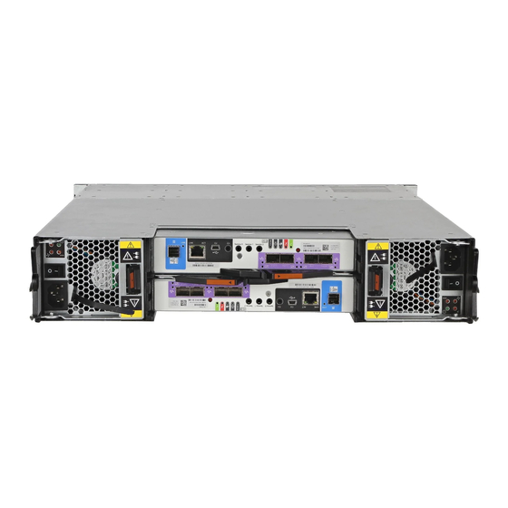
Upon completing the hardware installation, you can access the controller module’s web-based management interface—ME Storage Manager—to configure, monitor, and manage the storage system. The controller module also provides a CLI in support of command entry and scripting. For details, see the Dell EMC ME4 Series Storage System CLI Guide for your system. Operation... - Page 9 Figure 2. 2U12 enclosure system—rear orientation The 2U12 controller enclosure in Figure 2. 2U12 enclosure system—rear orientation is equipped with 2 controllers (4–port FC/ISCSI model shown). Figure 3. 2U24 enclosure system—front orientation Figure 4. 2U24 enclosure system—rear orientation The 2U24 controller enclosure is equipped with dual-controllers (4-port SAS model shown). Storage system hardware...
-
Page 10: Attach Or Remove The 2U Enclosure Front Bezel
Figure 5. 5U84 enclosure system—front orientation Figure 6. 5U84 enclosure system—rear orientation The 5U84 controller enclosure is equipped with dual-controllers (4-port FC/iSCSI model shown). Attach or remove the 2U enclosure front bezel The 2U12 controller enclosure in Figure 7. Attaching or removing the 2U enclosure front bezel is equipped with 2 controllers (4–port FC/ ISCSI model shown). -
Page 11: Enclosure Variants
You can attach or remove the optional 2U enclosure bezel. Locate the bezel, and while grasping it with your hands, face the front panel of the 2U12 or 2U24 enclosure. A partial view of a 2U12 enclosure is shown in Figure 7. -
Page 12: U Enclosure Core Product
Product Configuration PCMs IOMs ME424 12 Gb/s direct dock SFF SAS -Redundant PCMs must be compatible modules of the same type (both AC). -Supported controller module IOMs include 4-port FC/iSCSI, 4-port HD mini-SAS, and 4-port iSCSI 10Gbase-T. Supported expansion module IOMs are used in expansion enclosures for adding storage. -In single-controller configurations, the controller module installs into IOM slot A, and an IOM-blank is fitted to IOM slot B. -
Page 13: U Enclosure Rear Panel
Numeric designators on PCMs and alphabetic designators on IOMs indicate slot sequencing for modules used in 2U enclosures. PCM and IOM modules are available as CRUs. The ME4 Series RBODs use 4-port controller modules. These RBODs support the ME412/ME424/ ME484 EBODs for optionally adding storage. -
Page 14: Controller Module
A. In this orientation, the IOM latch appears at the bottom of the module. It is shown in closed/locked position. The diagrams below identify ports. Figure 31. LEDs: ME4 Series Storage System FC/iSCSI controller modules (FC and 10GbE SFPs) for LED identification. These diagrams also show proper orientation for IOM insertion into slots located on the 5U84 enclosure rear panel. - Page 15 • When the expansion module shown in Figure 17. Expansion module detail ME412/ME424/ME484 is used with ME4 Series controller modules for adding storage, its middle HD mini-SAS expansion port (“B”) is disabled by the firmware. • The Ethernet port on the expansion module is not used in controller/expansion enclosure configurations, and is disabled.
-
Page 16: U84 Enclosure Core Product
Power cooling module Figure 18. Power cooling module (PCM) shows the power cooling module (PCM) used in controller enclosures and optional expansion enclosures. The PCM includes integrated cooling fans. The example shows a PCM oriented for use in the left PCM slot of the enclosure rear panel. -
Page 17: U84 Enclosure Front Panel
5U84 enclosure front panel Figure 19. 5U84 enclosure—front panel components 5U84 enclosure drawer (slot 0 = top drawer) 5U84 enclosure drawer (slot 1 = bottom drawer) This figure shows a plan view of an enclosure drawer that is accessed from the enclosure front panel. The conceptual graphics are simplified for clarity. - Page 18 Figure 21. 5U84 controller enclosure—rear panel components (4-port FC/iSCSI) Controller module slot A Controller module slot B FCM slot 0 FCM slot 1 FCM slot 2 FCM slot 3 FCM slot 4 PSU slot 0 PSU slot 1 Figure 22. 5U84 controller enclosure—rear panel components (4-port SAS) Controller module slot A Controller module slot B FCM slot 0...
- Page 19 Figure 23. 5U84 controller enclosure—rear panel components (4-port iSCSI 10Gbase-T) Controller module slot A Controller module slot B FCM slot 0 FCM slot 1 FCM slot 2 FCM slot 3 FCM slot 4 PSU slot 0 PSU slot 1 Figure 24. 5U84 expansion enclosure—rear panel components Controller module slot A Controller module slot B FCM slot 0...
-
Page 20: Controller Modules
5U84 rear panel components This section describes the rear-panel controller modules, expansion module, power supply module, and fan cooling module. Controller modules The 5U84 controller enclosure uses the same IOMs used by 2U12 and 2U24 enclosures. See Figure 21. 5U84 controller enclosure—rear panel components (4-port FC/iSCSI) Figure 22. -
Page 21: U84 Enclosure Chassis
Figure 26. Fan cooling module (FCM) Module release latch Handle Module OK LED (Green) Fan Fault LED (Amber/blinking amber) LED behavior: • If any of the FCM LEDs are illuminated amber, a module fault condition or failure has occurred.. • For a detailed description of FCM LEDs, see Fan cooling module LEDs. -
Page 22: Operator's (Ops) Panel Leds
Table 18. Drawer LED descriptions. Operator's (Ops) panel LEDs Each ME4 Series enclosure features an Ops panel located on the chassis left ear flange. This section describes the Ops panel for 2U and 5U enclosures. 2U enclosure Ops panel A flexible cable connects the Ops panel to the midplane. The Ops panel is a passive component: the midplane controls the panel, and the IOMs control all the panel’s functions. - Page 23 Figure 28. LEDs: Ops panel—2U enclosure front panel Table 4. Ops panel functions (see left ear on 2U front panel) Indicator Status System power Constant green: at least one PCM is supplying power Off: system not operating regardless of AC present Constant blue: system is powered on and controller is ready Status/Health Blinking blue (2 Hz): Enclosure management is busy...
-
Page 24: U Enclosure Ops Panel
Identity LED (blue) When activated, the Identity LED blinks at a rate of 1 second on, 1 second off to easily locate the chassis within a data center. The locate function can be enabled or disabled through SES. Pressing the button toggles the state of the LED. Setting the enclosure ID using the System ID button is not supported by the firmware. -
Page 25: Controller And Expansion Modules
The diagrams with tables that immediately follow provide descriptions for the different controller modules that can be installed into the rear panel of ME4 Series controller enclosures. Showing controller modules separately from the enclosure enables improved clarity in identifying the component items called out in the diagrams and described in the companion tables within the figure/table ensembles. - Page 26 Alternatively, you can configure the 2U controller enclosure with a single-IOM. Install the controller module in IOM slot A, and fit the IOM-blank to IOM slot B. Figure 31. LEDs: ME4 Series Storage System FC/iSCSI controller modules (FC and 10GbE SFPs) Table 6. LEDs: ME4 Series controller modules (FC and iSCSI SFPs)
- Page 27 -Cache Status LED supports power on behavior and operational (cache status) behavior. See also Table 9. Cache Status LED – power on behavior -When port is down, both LEDs are off. Figure 32. LEDs: ME4 Series 10Gbase-T controller module Table 7. LEDs: ME4 Series 10Gbase-T controller module LED Description Definition Host 10Gbase-T iSCSI Off —...
- Page 28 - Cache Status LED supports power on behavior and operational (cache status) behavior. - When port is down, both LEDs are off. See also Table 9. Cache Status LED – power on behavior Figure 33. LEDs: ME4 Series SAS controller module Storage system hardware...
- Page 29 Table 8. LEDs: ME4 Series SAS controller module LED Description Definition Host 12 Gb SAS Green — The port is connected and the link is up. Link Status/ Amber — Partial link exists (one or more lanes down). Link Activity Blinking green or amber —...
-
Page 30: Compactflash
When a controller is shut down or otherwise rendered inactive—its Link Status LED remains illuminated— falsely indicating that the controller can communicate with the host. Though a link exists between the host and the chip on the controller, the controller is not communicating with the chip. -
Page 31: Supercapacitor Pack
CAUTION: For single-controller configuration only, to preserve the existing data stored in the CompactFlash, you must transport Dell EMC ME4 Series the CompactFlash from the failed controller to the replacement controller. This procedure is outlined in the Storage System Owner's Manual within the procedure for replacing a controller module. Failure to use this procedure will result in the loss of data stored in the cache module. -
Page 32: Cache Status Led – Corrective Action
NOTE: Remove the CompactFlash memory card only if recommended by Dell EMC technical support. Transportable cache only applies to single-controller configurations. In dual-controller configurations featuring one healthy partner controller, there is no need to transport failed controller cache to a replacement controller because the cache is duplicated between the controllers, provided that the volume cache is set to standard on all volumes in the pool owned by the failed controller. -
Page 33: Troubleshooting And Problem Solving
Troubleshooting and problem solving These procedures are intended to be used only during initial configuration, for the purpose of verifying that hardware setup is successful. They are not intended to be used as troubleshooting procedures for configured systems using production data and I/O. Topics: •... - Page 34 PCM OK Fan Fail AC Fail DC Fail Status (Green) (Amber) (Amber) (Amber) PCM fan speed is outside acceptable limits PCM fan has failed PCM fault (above temperature, above voltage, above current) Blinking Blinking Blinking PCM firmware download is in progress Ops panel LEDs The Ops panel displays the aggregated status of all the modules.
- Page 35 Disk drive carrier module LEDs Disk drive status is monitored by a green LED and an amber LED mounted on the front of each drive carrier module, as shown in the following figure. The drive module LEDs are identified in the figure, and the LED behavior is described in the table following the figure. •...
-
Page 36: U Enclosure Leds
Activity LED (Green) Fault LED (Amber) Status/condition* Blink off with activity Blinking: 3s on/ 1s off Storage system: Offline (dequarantined) Blink off with activity Storage system: Reconstruction Blink off with activity Processing I/O (whether from host or internal activity) *If multiple conditions occur simultaneously, the LED state behaves as indicated by the condition listed earliest in the table, as rows are read from top to bottom. - Page 37 Table 15. PSU LED states CRU Fail AC Missing Power Status (Amber) (Amber) (Green) No AC power to either PSU PSU present, but not supplying power or PSU alert state. (usually due to critical temperature) Mains AC present, switch on. This PSU is providing power. Blinking AC power present, PSU in standby (other PSU is providing power).
- Page 38 Status/description Drawer 1 Amber indicates a disk, cable, or sideplane fault in drawer 1. Open the drawer and check DDICs for faults. Fault Drawer LEDs #unique_41/GUID-584C583E-8246-4808-8F6E-438F4FF90117 for a visual description of the Drawer LED inserts located on each drawer bezel. Table 18.
-
Page 39: Troubleshooting 2U Enclosures
Fault LED (Amber) Status/description* Any links down: On Drive link (PHY lane) down Fault (leftover/failed/locked-out) Available Storage system: Initializing Storage system: Fault-tolerant Storage system: Degraded (non-critical) Blinking: 3s on/1s off Storage system: Degraded (critical) Storage system: Quarantined Blinking: 3s on/1s off Storage system: Offline (dequarantined) Storage system: Reconstruction Processing I/O (whether from host or internal activity) -
Page 40: Pcm Faults
Status Severity Alarm Over temperature alarm Fault – critical C bus failure Fault – loss of redundancy Ops panel communication error (I Fault – critical RAID error Fault – critical SBB interface module fault Fault – critical SBB interface module removed Warning None Drive power control fault... -
Page 41: Thermal Alarm
Symptom Cause Recommended action may be causing additional reached. This may be caused by Check for excessive re-circulation of heated air from rear to internal temperature rise. higher ambient temperatures in front. Use of the enclosure in a fully enclosed rack is not recommended. -
Page 42: Thermal Considerations
5U alarm conditions. CLI port connections ME4 Series Storage System controllers feature a CLI port employing a 3.5mm stereo plug and a mini-USB Type B form factor. For more information about connecting a serial cable, see Appendix A of this manual. -
Page 43: Gather Fault Information
Options available for performing basic steps When performing fault isolation and troubleshooting steps, select the option or options that best suit your site environment. Use of any option (four options are described below) is not mutually exclusive to the use of another option. You can use the ME Storage Manager to check the health icons/values for the system and its components to ensure that everything is okay, or to drill down to a problem component. -
Page 44: Determine Where The Fault Is Occurring
Begin by reviewing the reported fault: • Is the fault related to an internal data path or an external data path? • Is the fault related to a hardware component such as a disk drive module, controller module, or power supply unit? By isolating the fault to one of the components within the storage system, you will be able to determine the necessary corrective action more quickly. -
Page 45: Temperature Sensors
enclosure IDs, if possible. To correct this condition, make sure that both controllers are up, and perform a rescan using the ME Storage Manager or the CLI. This will reorder the enclosures, but can take up to two minutes for the enclosure IDs to be corrected. To perform a rescan using the CLI, type the following command: rescan To perform a rescan using the ME Storage Manager:... -
Page 46: Module Removal And Replacement
Module removal and replacement Overview This chapter provides procedures for replacing CRUs (customer-replaceable units), including precautions, removal instructions, installation instructions, and verification of successful installation. Each procedure addresses a specific task. Certain procedures See related documentation. ESD precautions Before you begin any of the procedures, consider the following precautions and preventive measures. Preventing electrostatic discharge To prevent electrostatic discharge (ESD) from damaging the system, be aware of the precautions to consider when setting up the system or handling parts. -
Page 47: Dealing With Hardware Faults
The ME Storage Manager and CLI provide an option for enabling or disabling PFU for the partner controller as described in the Dell EMC ME4 Series Storage System Administrator’s Guide. To enable or disable the setting via the CLI, use the set advanced- settings command, and set the partner-firmware-upgrade parameter. -
Page 48: Using The Me Storage Manager
If an iSCSI port is connected to a Microsoft Windows host, the following event is recorded in the Windows event log: Initiator failed to connect to the target. • See the Dell EMC ME4 Series Storage System Administrator’s Guide for additional information. Using the CLI Log-in to the CLI. -
Page 49: Customer-Replaceable Units (Crus)
Customer-replaceable units (CRUs) NOTE: Figure 38. SBB IOMs used in ME4 Series storage enclosures for pictorial views of IOM CRUs used in the different enclosure form factors supported by ME4 Series Storage System. Table 25. ME4 Series enclosure models ME4 Series: 4–port controller enclosure matrix - 2U 2.5"... - Page 50 Replacing a 2U12–drive chassis This section describes 2U12–drive chassis product components. Table 27. ME4 Series Storage System product components for 2U 12-drive chassis Item Enclosure component description Disk drive (LFF) a) 3.5"...
- Page 51 2U 12-drive ME4 Series enclosures. Modules are shown oriented for insertion into IOM slot A located on the 2U enclosure rear panel. This orientation also applies to both IOM slots in 5U84 enclosures.
- Page 52 2U 24-drive ME4 Series enclosures. Modules are shown oriented for insertion into IOM slot A located on the 2U enclosure rear panel. This orientation also applies to both IOM slots in 5U84 enclosures.
-
Page 53: Replacing A Disk Drive Carrier Module
Figure 38. SBB IOMs used in ME4 Series storage enclosures 4-port FC/iSCSI 4-port HD mini-SAS 4-port 10GbaseT 3-port expansion Replacing a disk drive carrier module A disk drive module consists of a disk in a carrier or sled. Disk drive modules are hot-swappable, which means they can be replaced without halting I/O to the disk groups, or powering off the enclosure. - Page 54 When moving FDE-capable disk drive modules for a disk group, stop I/O to the disk group before removing the disk drive modules. Import the keys for the disks so that the disk content becomes available. See the Dell EMC ME4 Series Storage System Administrator’s Guide or Dell EMC ME4 Series Storage System CLI Guide for more information.
- Page 55 Figure 40. Removing a LFF disk drive module (2 of 2) Remove the module fully from the drive slot. CAUTION: To ensure optimal cooling throughout the enclosure, blank drive carrier modules must be installed in all unused drive slots. Installing a LFF drive carrier module Release the drive carrier handle by depressing the latch in the handle.
- Page 56 Figure 42. Installing a LFF drive carrier module (1 of 2) Slide the drive carrier fully into the enclosure. Cam the drive carrier home. The camming foot on the carrier will engage into a slot in the enclosure. Continue to push firmly until the handle fully engages.
- Page 57 Figure 44. Removing a SFF disk drive module (1 of 2) Gently move the drive carrier module outward from the drive slot. Figure 45. Removing a SFF disk drive module (2 of 2) Remove the module fully from the drive slot. CAUTION: To ensure optimal cooling throughout the 2U enclosure, blank drive carrier modules must be fitted to all unused drive slots.
- Page 58 Figure 46. SFF drive carrier module in open position Slide the carrier fully into the enclosure until it is stopped by the camming lever on the bottom of the carrier. Figure 47. Installing a SFF drive carrier module (1 of 2) Cam the carrier home.
- Page 59 Figure 48. Installing a SFF drive carrier module (2 of 2) Using the management interfaces (the ME Storage Manager or CLI), verify the following: • the health of the new disk is OK • the green Disk Activity LED is on/blinking •...
- Page 60 Figure 49. Removing and installing a drive into a 2.5 inch drive carrier drive carrier l drive screws (4) Module removal and replacement...
- Page 61 Figure 50. Removing and installing a 3.5 inch drive into a drive carrier physical drive carrier physical drive screws (4) Installing a drive into a drive carrier Many repairs can only be done by a certified service technician. Only perform troubleshooting and simple repairs as authorized in your product documentation, or as directed by the online or telephone service and support team.
- Page 62 • If the disk has failed, a fault LED is lit on the front panel of the affected drawer. The illuminated LED will either be the Drawer LED or the Logical LED. • If the disk has failed, the Drive Fault LED on the DDIC cover is lit amber. Open the relevant drawer.
- Page 63 Installing the hard drive into the carrier Replacement drives are not shipped with new disk drive carrier. The replacement drive must be placed into the carrier that held the failed drive. Module removal and replacement...
- Page 64 Module removal and replacement...
-
Page 65: Installation Guidelines
Contact your account manager for part numbers. • If the two groups of disks have different firmware, all disks must be updated with current/compatible firmware. See the Dell EMC ME4 Series Storage System Administrator’s Guide or online help for additional information about updating firmware. -
Page 66: Replacing An I/O Module (Iom)
• Figure 51. Removing a DDIC (1 of 2) shows dual-indexing of disk slots across front, middle, and back rows of a drawer. The 5U84 ships with drawers installed in the chassis. However, to avoid shock and vibration issues during transit, the enclosure does not ship with DDICs installed in the drawers. - Page 67 Figure 54. CompactFlash memory card location CompactFlash memory card (installed/removed) IOM viewed from back (midplane-facing orientation) Confirm that transporting CompactFlash is the appropriate action to take as discussed in the ME4 Series Storage System Deployment Guide. Refer to Figure 54. CompactFlash memory card location when performing the step-procedure below.
- Page 68 NOTE: Considerations for removing controller modules: • In a dual-controller environment, you may hot-swap a single controller module in an operational enclosure, provided you first shut down the faulty controller using theME Storage Manager or the CLI. • In a dual-controller environment—if replacing both controller modules—you must adhere to the instructions provided in precautions.
- Page 69 Figure 56. Removing an IOM Grip the latch handle and ease the IOM forward from the slot as shown in detail No.2 within Figure 55. IOM latch operation detail. NOTE: Figure 56. Removing an IOM shows a 4-port SAS controller module. However, the procedure applies to all IOMs discussed herein.
- Page 70 You should hear a click as the latch handle engages and secures the IOM to its connector on the back of the midplane. Reconnect the cables. NOTE: In a dual-controller system in which PFU is enabled, when you update the firmware on one controller, the system automatically updates the partner controller.
-
Page 71: Replacing A Power Supply Unit (Psu)
Figure 58. Removing an IOM NOTE: Although the figure shows a controller module instead of an expansion module, the form factors are very similar and the latching mechanisms are identical. Grip the latch handle and ease the IOM forward from the slot as shown in detail No.2 within Figure 56. - Page 72 Before removing the PSU, disconnect the power from the PSU by either the mains switch (where present) or by physically removing the power source in order to ensure your system has warning of imminent power shutdown. Ensure that you correctly identify the faulty PSU before beginning the step procedure.
-
Page 73: Replacing A Fan Cooling Module (Fcm)
Installing a PSU Ensure that the PSU is switched off. If replacing both PSUs, the enclosure must be powered off via an orderly shutdown using the management interfaces. Orient the PSU for insertion into the target slot on the enclosure rear panel, as shown in Figure 59. - Page 74 Figure 61. Removing an FCM (1 of 2) Figure 62. Removing an FCM (2 of 2) NOTE: The FCM slot must not be empty for more than 2 minutes while the enclosure is powered. Installing an FCM You can hotswap the replacement of a single FCM; however, if replacing multiple FCMs, the enclosure must be powered off using an orderly shutdown using the management interfaces.
-
Page 75: Replacing A Power Cooling Module (Pcm)
Replacing a power cooling module (PCM) This section provides procedures for replacing a failed power cooling module (PCM). Illustrations in PCM replacement procedures show rear panel views of the enclosure, with the PCM properly oriented for insertion into the rear panel of the enclosure. A single PCM is sufficient to maintain operation of the enclosure. - Page 76 Figure 63. Removing a PCM (1 of 2) Grip the handle and withdraw the PCM, taking care to support the base of the module with both hands as you remove it from the enclosure as shown in Figure 64. Removing a PCM (2 of Figure 64.
-
Page 77: Completing The Component Installation Process
Cam the module home by manually closing the PCM handle. You should hear a click as the latch handle engages and secures the PCM to its connector on the back of the midplane. Connect the power cable to the power source and the PCM. Secure the strain relief bales. -
Page 78: Using Management Interfaces
Verify rear panel LEDs Rear panel LEDs are located on PCM and IOM face plates. • Verify that each power cooling module’s PCM OK LED is illuminated green. • For IOMs, verify that the OK LED is illuminated green, indicating that the module has completed initializing, and is online. Using management interfaces In addition to viewing LEDs as previously described, you can use management interfaces to monitor the health status of the system and its components, provided you have configured and provisioned the system, and enabled event notification. -
Page 79: Installing The Replacement 2U Storage Enclosure In The Rack
This section provides the procedure for installing the replacement enclosure in its rack location. NOTE: • See the ME4 Series Storage System Deployment Guide when installing the enclosure into the rack. • Install the enclosure into the rack before re-inserting the disk drive modules. Two people are required to move the enclosure. -
Page 80: Events And Event Messages
Events and event messages When an event occurs in a storage system, an event message is recorded in the system’s event log and, depending on the system’s event notification settings, can also be sent to users (using email) and host-based applications (using SNMP or SMI-S). TIP: A best practice is to enable notifications to be sent for events having severity Warning and higher. -
Page 81: Events
Events Number Severity Description/Recommended actions Warning The disk group is online but cannot tolerate another disk failure. • If the indicated disk group is RAID 6, it is operating with degraded health due to the failure of two disks. • If the indicated disk group is not RAID 6, it is operating with degraded health due to the failure of one disk. - Page 82 Number Severity Description/Recommended actions tolerant with a down disk), CRIT (critical), or OFFL (offline), depending on the RAID level and the number of disks that failed. Recommended actions: • Look for another event logged at approximately the same time that indicates a disk failure, such as event 55, 58, or 412.
- Page 83 Number Severity Description/Recommended actions ◦ If the disk then has a status of leftover (LEFTOVR), clear the metadata to reuse the disk. ◦ If the associated disk group is offline or quarantined, contact technical support. • If reconstruction of a disk group failed: –...
- Page 84 Number Severity Description/Recommended actions Info. Storage Controller firmware update has completed. Recommended actions: • No action is required. Error Disk group verification completed. Errors were found but not corrected. Recommended actions: • No action is required. Warning Disk group verification did not complete because of an internally detected condition such as a failed disk. If a disk fails, data may be at risk.
- Page 85 Number Severity Description/Recommended actions • No action is required. Info. Controller time/date has been changed. This event is logged before the change happens, so the timestamp of the event shows the old time. This event may occur often if NTP is enabled. Recommended actions: •...
- Page 86 Number Severity Description/Recommended actions Recommended actions: • No action is required. Warning The controller contains cache data for the indicated volume but the corresponding disk group is not online. Recommended actions: • Determine the reason that the disks comprising the disk group are not online. •...
- Page 87 Number Severity Description/Recommended actions Info. Disk group expansion has started. This operation can take days, or weeks in some cases, to complete. Allow adequate time for the expansion to complete. When complete, event 53 is logged. Recommended actions: • No action is required. Warning Too many errors occurred during disk group expansion to allow the expansion to continue.
- Page 88 Number Severity Description/Recommended actions SAS, or midline SAS) and the same or greater capacity. For continued optimum I/O performance, the replacement disk should have performance that is the same as or better than the one it is replacing. Info. A disk drive reported an event. Recommended actions: •...
- Page 89 Number Severity Description/Recommended actions Recommended actions: • No action is required. Info. The two controllers are communicating with each other and cache redundancy is enabled. Recommended actions: • No action is required. Info. The FC loop ID for the indicated disk group was changed to be consistent with the IDs of other disk groups. This can occur when disks that constitute a disk group are inserted from an enclosure having a different FC loop ID.
- Page 90 Number Severity Description/Recommended actions Recommended actions: • Be sure to complete the trust procedure as documented in the CLI help for the trust command. Info. The controller enabled or disabled the indicated parameters for one or more disks. Recommended actions: •...
- Page 91 Number Severity Description/Recommended actions Recommended actions: • No action is required. Error In a testing environment, the diagnostic that checks hardware reset signals between controllers in Active- Active mode failed. Recommended actions: • Perform failure analysis. Error Both controllers in an Active-Active configuration have the same serial number. Non-unique serial numbers can cause system problems.
- Page 92 Number Severity Description/Recommended actions Info. The statistics for the indicated volume have been reset. Recommended actions: • No action is required. Info. Ownership of the indicated disk group has been given to the other controller. Recommended actions: • No action is required. Info.
- Page 93 Number Severity Description/Recommended actions Recommended actions: • No action is required. Warning The controller has detected an invalid disk dual-port connection. This event indicates that a controller host port is connected to an expansion port, instead of to a port on a host or a switch. Recommended actions: •...
- Page 94 Number Severity Description/Recommended actions If communication is restored in less than 15 minutes, event 153 is logged. If the problem persists, this event is logged a second time as Warning severity. NOTE: It is normal for this event to be logged as Informational severity during firmware update. Recommended actions: •...
- Page 95 Number Severity Description/Recommended actions All enclosure EMPs are disabled. Recommended actions: • Download the debug logs from your storage system and contact technical support. A service technician can use the debug logs to determine the problem. Warning The host WWNs (node and port) previously presented by this controller module are unknown. In a dual- controller system this event has two possible causes: •...
- Page 96 Number Severity Description/Recommended actions Recommended actions: • No action is required. Warning The indicated disk group was quarantined for one of the following reasons: • Not all of its disks are accessible. While the disk group is quarantined, in linear storage any attempt to access its volumes in the disk group from a host will fail.
- Page 97 Number Severity Description/Recommended actions If the firmware update fails, the user will be notified about the problem immediately and should take care of the problem at that time, so even when there is a failure, this event is logged as Informational severity. Recommended actions: •...
- Page 98 Number Severity Description/Recommended actions • No action is required. Info. Enclosure parameters have been changed by a user. Recommended actions: • No action is required. Info. The write-back cache has been enabled. Event 188 is the corresponding event that is logged when write-back cash is disabled. Recommended actions: •...
- Page 99 Number Severity Description/Recommended actions Info. The Storage Controller in the partner controller module is not up. This indicates that a trigger condition has occurred that has caused the auto-write-through feature to disable write-back cache and put the system in write-through mode. When the fault is resolved, event 195 is logged to indicate that write-back mode has been restored.
- Page 100 Number Severity Description/Recommended actions Recommended actions: • Manually enable write-back cache. Error An error occurred with either the NV device itself or the transport mechanism. The system may attempt to recover itself. The CompactFlash card is used for backing up unwritten cache data when a controller goes down unexpectedly, such as when a power failure occurs.
- Page 101 Number Severity Description/Recommended actions For non-fault-tolerant RAID levels (RAID 0 and non-RAID), media errors may indicate loss of data. Recommended actions: • Resolve any non-disk hardware problems, such as a cooling problem or a faulty controller module, expansion module, or power supply. •...
- Page 102 Number Severity Description/Recommended actions Info. A scrub-disk job logged with event 208 has completed and found no errors, or a disk being scrubbed (with no errors found) has been added to a disk group, or a user has aborted the job. Recommended actions: •...
- Page 103 Number Severity Description/Recommended actions Warning The indicated disk type is invalid and is not allowed in the current configuration. All disks of the disallowed type have been removed from the configuration. Recommended actions: • Replace the disallowed disks with ones that are supported. Error An enclosure management processor (EMP) detected a serious error.
- Page 104 Number Severity Description/Recommended actions Recommended actions: • Restart the Storage Controller that logged this event. • If this event is logged again, shut down the Storage Controller and replace the CompactFlash. • If this event is logged again, shut down the Storage Controller and replace the controller module. Info.
- Page 105 Number Severity Description/Recommended actions Info. After a valid license is installed, this event is logged for each licensed feature to show the new license value for that feature. The event specifies whether the feature is licensed, whether the license is temporary, and whether the temporary license is expired.
- Page 106 Number Severity Description/Recommended actions Recommended actions: • Replace the disk with one of the same type (SSD, enterprise SAS, or midline SAS) and the same or greater capacity. • Configure the disk as a spare. Info. A volume-copy operation for the indicated master volume has been aborted by a user. Recommended actions: •...
- Page 107 Number Severity Description/Recommended actions • No action is required. Info. PHY fault isolation has been enabled or disabled by a user for the indicated enclosure and controller module. Recommended actions: • No action is required. Warning The indicated PHY has been disabled, either automatically or by a user. Drive PHYs are automatically disabled for empty disk slots or if a problem is detected.
- Page 108 Number Severity Description/Recommended actions Recommended actions: • Check the system date and time. If either is incorrect, set them to the correct date and time. • Also look for event 246 and follow the recommended action for that event. When the problem is resolved, event 299 is logged. Info.
- Page 109 Number Severity Description/Recommended actions • Check that the storage system’s fans are running. • Check that the ambient temperature is not too warm. The controller enclosure operating range is 5°C to 35°C (41°F to 95°F). The expansion enclosure operating range is 5°C to 40°C (41°F to 104°F). •...
- Page 110 Number Severity Description/Recommended actions Recommended actions: • To continue using the feature, purchase a permanent license. Info. The temporary license for a feature will expire in 10 days. Any components created with the feature will remain accessible but new components cannot be created. Recommended actions: •...
- Page 111 Number Severity Description/Recommended actions Recommended actions: • No action is required. Warning This event can only result from tests that are run in the manufacturing environment. Recommended actions: • Follow the manufacturing process. Warning This event can only result from tests that are run in the manufacturing environment. Recommended actions: •...
- Page 112 Number Severity Description/Recommended actions Recommended actions: • Take appropriate action based on the indicated problem. Info. The scheduler experienced a problem with the indicated task. Recommended actions: • No action is required. Error When the Management Controller (MC) is restarted, firmware versions that are currently installed are compared against those in the bundle that was most recently installed.
- Page 113 Number Severity Description/Recommended actions Recommended actions: • Investigate why the log-collection system is not transferring the logs before they are overwritten. For example, you might have enabled managed logs without configuring a destination to send logs to. Warning One disk in the indicated RAID-6 disk group failed. The disk group is online but has a status of FTDN (fault tolerant with a down disk).
- Page 114 Number Severity Description/Recommended actions Recommended actions: • No action is required. Info. Disk groups were added to the indicated virtual pool. Recommended actions: • No action is required. Info. Removal of the indicated disk group(s) was started. When this operation is complete, event 470 is logged. Recommended actions: •...
- Page 115 Number Severity Description/Recommended actions virtual volumes exceeds the physical space in the virtual pool. If the storage usage drops below a threshold, event 463 is logged. Recommended actions: • No action is required for the low and mid thresholds. However, you may want to determine if your storage usage is growing at a rate that will result in the high threshold being crossed in the near future.
- Page 116 Number Severity Description/Recommended actions • If none of the above explanations apply, replace the controller module that logged the error. When the problem is resolved, event 468 is logged. Warning Removal of the indicated disk group(s) completed with failure. Removal of disk groups can fail for several reasons, and the specific reason for this failure is included with the event.
- Page 117 Number Severity Description/Recommended actions • Check that there is a module or blank plate in every module slot in the enclosure. • If none of the above explanations apply, replace the controller module that logged the error. When the problem is resolved, event 478 is logged. Info.
- Page 118 Number Severity Description/Recommended actions If the last global spare has been deleted or used for reconstruction, ALL disk groups that do not have at least one dedicated or global spare are at increased risk. Note that even though there may be global spares still available, they cannot be used for reconstruction of a disk group if that disk group uses larger-capacity disks or a different type of disk.
- Page 119 Number Severity Description/Recommended actions • Wait at least 5 minutes for the automatic recovery process to complete. Then sign in and confirm that both controller modules are operational. (You can determine if the controllers are operational with the CLI show redundancy-mode command.) In most cases, the system will come back up and no action is required.
- Page 120 Number Severity Description/Recommended actions – Check for disconnected SAS cables in the bad path. If no cables are disconnected, replace the cable connecting to the ingress port in the most-upstream enclosure with reported failures. If that does not resolve the problem, replace other cables in the bad path, one at a time until the problem is resolved. –...
- Page 121 Number Severity Description/Recommended actions • No action is required. Warning The indicated virtual pool was created with a size smaller than 500 GB, which can lead to unpredictable behavior. The storage system may not perform correctly. Recommended actions: • Add disk groups to the virtual pool to increase the size of the pool. Info.
- Page 122 Number Severity Description/Recommended actions This is normally used to import into the system an FDE disk that was locked by another system. Recommended actions: • Ensure that the imported disk(s) are integrated into the system. Info. The system was set to the FDE secured state by a user. Full Disk Encryption is now enabled.
- Page 123 Number Severity Description/Recommended actions The midplane’s memory is used to store the FDE lock key. Recommended actions: • The midplane may need to be replaced if the error persists. Warning A scrub-disk-group job encountered an error at the indicated logical block address. The event message always includes the disk group name and the logical block address of the error within that disk group.
- Page 124 Number Severity Description/Recommended actions As a preventative measure, the Expander Controller (EC) disabled all PHYs and reported the short enclosure status page in the supported diagnostic list. Recommended actions: • Upgrade the controller module to the latest supported bundle version. Error Expander Controller firmware detected that the partner Expander Controller (EC) firmware is incompatible with the enclosure.
- Page 125 Number Severity Description/Recommended actions • No action is required. Critical A data block was fenced by the controller due to lost data. Event 543 will also be logged to describe volume information for the fenced data block. Recommended actions: • Perform recovery procedures, which may include restoring from backups.
- Page 126 Number Severity Description/Recommended actions Error An EMP reported one of the following for a power supply unit (PSU): • The PSU is unable to communicate with the EMP. • The PSU in an enclosure does not have power supplied to it or has a hardware failure. •...
- Page 127 Number Severity Description/Recommended actions – Wait for at least 10 minutes and check if the error resolves. – If the error persists, check that all modules in the enclosure are fully seated in their slots and that their latches, if any, are locked. –...
- Page 128 Number Severity Description/Recommended actions – For all FRU types except the enclosure, if the partner FRU is not degraded, remove and reinsert the indicated FRU. – If the indicated FRU is the enclosure, set up a preventive maintenance window and power cycle the enclosure at that time.
- Page 129 Number Severity Description/Recommended actions If a voltage sensor has exceeded the normal operating range but is within safe operating limits: • Check that all modules in the enclosure are fully seated in their slots and that their latches are locked. •...
- Page 130 Number Severity Description/Recommended actions Recommended actions: • If uninstalled, the expander associated with the sideplane or drawer will have to be installed. Contact technical support. Otherwise, replace the module that contains the indicated expander. This could be a sideplane or a drawer. Contact technical support for replacement of the module containing the drawer expander.
- Page 131 Number Severity Description/Recommended actions Resolved A SES alert for a current sensor in the indicated enclosure has been resolved. Recommended actions: • No action is required. Info. Virtual pool statistics have been reset. Recommended actions: • No action is required. Info.
- Page 132 Number Severity Description/Recommended actions Recommended actions: • Reduce the snapshot space usage by deleting snapshots that are no longer needed. Info. Allocated snapshot space exceeded either the low or middle snapshot space threshold. The threshold settings are intended to indicate that the pool is using a significant portion of configured snapshot space and should be monitored.
- Page 133 Number Severity Description/Recommended actions Recommended actions: • Resolve the issue specified by the error message included with this event. Info. A replication was started. Recommended actions: • No action is required. Warning A replication completed with failure. The replication was unsuccessful due to the condition specified within the event. Reasons for replication failure include but are not limited to shutdown of the secondary system, a loss of communication across the peer connection (which may be due to CHAP configuration changes), or a pool out of space condition.
- Page 134 Number Severity Description/Recommended actions Error Resuming the replication was unsuccessful due to the condition specified within the event. Reasons for replication failure include but are not limited to shutdown of the secondary system, a loss of communication across the peer connection (which may be due to CHAP configuration changes), or a pool out-of-space condition.
- Page 135 Number Severity Description/Recommended actions CAUTION: • Avoid using the manual dequarantine operation as a recovery method when event 172 is logged because this causes data recovery to be more difficult or impossible. • If you clear unwritten cache data while a disk group is quarantined or offline, that data will be permanently lost.
- Page 136 Number Severity Description/Recommended actions The Midplane Interconnect element reports status associated with the interface between the SBB I/O module and the midplane. This is typically some form of communication problem on the midplane interconnect. Recommended actions: • Contact technical support. Provide logs to technical support personnel for analysis. •...
- Page 137 Number Severity Description/Recommended actions Recommended actions: • Verify that the cache-write policy is write-through for all volumes. • Contact technical support for information about replacing the controller module. Warning The local controller is rebooting the other controller. Recommended actions: • No action is required.
- Page 138 Number Severity Description/Recommended actions Recommended actions: • No action is required. Error Email notification failed due to either: • An unreachable SMTP server or a difference between the sender and SMTP server domains. • Improper configuration. • Recommended actions: – Verify the configured parameters and ask the recipients to confirm that they received the message. Info.
-
Page 139: Using The Trust Command
Number Severity Description/Recommended actions Recommended actions: • No action is required. Warning The spare capacity goal is not met. This event indicates that the available space in the system is insufficient to provide the level of full fault tolerance that is specified by the target spare capacity. Spare capacity availability can be influenced by operations that require available space in the system, such as reconstructing data from a failed disk. -
Page 140: Events Sent As Indications To Smi-S Clients
Once the trust command has been issued on a disk group, further troubleshooting steps may be limited towards disaster recovery. If you are unsure of the correct action to take, contact technical support for further assistance. Events sent as indications to SMI-S clients If the storage system’s SMI-S interface is enabled, the system will send events as indications to SMI-S clients so that SMI-S clients can monitor system performance. - Page 141 Connecting through the CLI port using a serial cable To connect through the CLI port using a serial cable, you must use the 3.5mm stereo plug CLI port and the supplied 3.5mm/DB9 serial cable. Alternatively, you can use a generic mini-USB cable (not included) and the USB CLI port. If you plan on using a mini-USB cable, you will need to enable the port for communication.
-
Page 142: Mini-Usb Device Connection
Once attached to the controller module, the management computer should detect a new USB device. Using the Emulated Serial Port interface, the ME4 Series controller presents a single serial port using a customer vendor ID and product ID. Effective presentation of the emulated serial port assumes the management computer previously had terminal emulator installed. -
Page 143: Supported Host Applications
Verify that the management computer has Internet access. Although Linux operating systems do not require installation of a device driver, certain parameters must be provided during driver loading to enable recognition of the ME4 Series controller enclosures. Connecting through the CLI port using a serial cable... -
Page 144: Using The Cli Port And Mini-Usb Cable—Known Issues On Windows
Setting parameters for the device driver Enter the following command: modprobe usbserial vendor=0x210c product=0xa4a7 use_acm=1 Press Enter to execute the command. The Linux device driver is loaded with the parameters required to recognize the controllers. NOTE: Optionally, this information can be incorporated into the /etc/modules.conf file. Using the CLI port and mini-USB cable—known issues on Windows When using the CLI port and cable for setting network port IP addresses, be aware of the following known issues on Microsoft Windows... -
Page 145: Using The Usb Cli Port And Cable—Known Issues On Windows
Set network port IP addresses using the CLI. See Setting network port IP address NOTE: When using Windows 10/Server 2016 with PuTTY, the XON/XOFF setting must be disabled, or the COM port will not open. Using the USB CLI port and cable—known issues on Windows When using the CLI port and cable for setting network port IP addresses, be aware of the following known issues on Microsoft Windows platforms. -
Page 146: Enclosure Dimensions
Technical specifications Enclosure dimensions Table 32. 2U enclosure dimensions Specification Metric units Imperial units Overall enclosure height (2U) 87.9 mm 3.46 in Width across mounting flange (located on 483 mm 19.01 in front of chassis) Width across body of enclosure 443 mm 17.44 in Depth from face of mounting flange to back... -
Page 147: Enclosure Weights
Enclosure weights CRU/component 2U12 (kg/lb) 2U24 (kg/lb) 5U84 (kg/lb) Storage enclosure (empty) 4.8/10.56 4.8/10.56 64/141 Disk drive carrier 0.9/1.98 0.3/0.66 0.8/1.8 Blank disk drive carrier (air management 0.05/0.11 0.05/0.11 — sled) Power Cooling Module (PCM) 3.5/7.7 3.5/7.7 — Power Supply Unit (PSU) —... -
Page 148: Power Cooling Module
Specification Measurement/description Maximum operating temperature is de-rated by 5ºC above 2,133 meters (7,000 feet) 5U84 enclosures: -100 to 3,000 meters (-330 to 10,000 feet) Maximum operating temperature is de-rated by 1ºC above 900 meters (3,000 feet) Altitude, non-operating -100 to 12,192 meters (-330 to 40,000 feet) Shock, operating 5.0 g, 10 ms, ½... -
Page 149: Power Supply Unit
Specification Measurement/description Power factor correction > 95% @ nominal input voltage Efficiency 115 VAC/60 Hz 230 VAC/50 Hz > 80% @ 10% load > 80% @ 10% load > 87% @ 20% load > 88% @ 20% load > 90% @ 50% load >... -
Page 150: International Standards
Standards and regulations International standards The enclosure system complies with the requirements of the following agencies and standards: • CE to EN 60950-1 • CB report to IEC 60950-1 • UL & cUL to UL 60950-1 second edition Potential for radio frequency interference USA Federal Communications Commission (FCC) NOTE: This equipment has been tested and found to comply with the limits for a class A digital device, pursuant to Part 15 of the... -
Page 151: Dell Emc Compliance
Dell EMC compliance Table 38. Dell EMC compliance specifications Conducted emissions limit levels CFR47 Part 15B Class A EN55022 Class A CISPR Class A Radiated emissions limit levels CFR47 Part 15B Class A EN55022 Class A CISPR Class A Harmonics and flicker... -
Page 152: Recycling Of Waste Electrical And Electronic Equipment (Weee)
Recycling of Waste Electrical and Electronic Equipment (WEEE) At the end of the product’s life, all scrap/waste electrical and electronic equipment should be recycled in accordance with national regulations applicable to the handling of hazardous/toxic electrical and electronic waste materials. Contact your supplier for a copy of the Recycling Procedures applicable to your country.
Need help?
Do you have a question about the ME4 Series and is the answer not in the manual?
Questions and answers