
Related Manuals for Daikin RMKD112DVM


Summary of Contents for Daikin RMKD112DVM
- Page 1 Si18-797 REMOVAL PROCEDURE S E R V I C E M A N U A L 11.2/14.0/16.0 kW Class Outdoor Unit Inverter Multi Type...
- Page 2 Service Manual Removal Procedure Outdoor Unit Cooling Only Heat Pump RMKD112DVM RMXS112DV1A RMKD140DVM RMXS140DV1A RMKD160DVM RMXS160DV1A RMKS112DV1A RMXS112DVLT RMKS140DV1A RMXS140DVLT RMKS160DV1A RMXS160DVLT RMKS112DVM RMXS112DVM RMKS140DVM RMXS140DVM RMKS160DVM RMXS160DVM BP Unit BPMKS967A2 BPMKS967A3 BPMKS967A2B BPMKS967A3B...
-
Page 3: Table Of Contents
Si18-797 Table of Contents 1. Outdoor Unit....................2 1.1 Removal of Outer Panels .................2 1.2 Removal of PCB..................9 1.3 Removal of Solenoid Valve, Four Way Valve and Motorized Valve..20 1.4 Removal of Thermistor Assembly ............21 1.5 Removal of Fan Motor................22 2. BP Unit ....................25 2.1 Removal of PCB..................25 2.2 Removal of Solenoid Valve Coil .............28 Note:... -
Page 4: Outdoor Unit
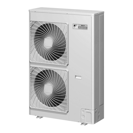
Outdoor Unit Si18-797 1. Outdoor Unit Removal of Outer Panels Procedure Warning Be sure to wait 10 minutes or more after turning off all power supplies before disassembling work. Step Procedure Points 1. Appearance Top panel Front panel Pipe outlet port (Q0446) Rear protective net Outdoor air... - Page 5 Si18-797 Outdoor Unit Step Procedure Points 2. Remove the rear protective net. Hooks Undo the 3 top hooks Bend the rear protective net first. slightly for easy removal. (Q0448) Next, undo the 4 right- side hooks. (See the figure at bottom.) (Q0449) Remove the rear protective net.
- Page 6 Outdoor Unit Si18-797 Step Procedure Points 3. Remove the top panel. Remove the 8 screws. (Q0451) Lift and remove the top panel. (Q0452) Removal Procedure...
- Page 7 Si18-797 Outdoor Unit Step Procedure Points 4. Remove the front panel. Remove the screw. Pull the front panel toward yourself. Screw (Q0453) There are 6 hooks on the front panel. Slide the front panel downward to remove it. (Q0454) Removal Procedure...
- Page 8 Outdoor Unit Si18-797 Step Procedure Points 5. Remove the pipe cover. Remove the screw. Pull the pipe cover toward yourself. Screw (Q0455) There are 3 hooks on the pipe cover. Slide the pipe cover upward to remove it. (Q0456) Removal Procedure...
- Page 9 Si18-797 Outdoor Unit Step Procedure Points 6. Right side panel Remove the 6 screws off the panel's front. Screws (Q0457) Remove the 3 screws off the panel's back and the 2 screws off the panel's side. Screws Screws (Q0458) Remove the right side panel.
- Page 10 Outdoor Unit Si18-797 Step Procedure Points 7. Remove the outdoor air thermistor. Disconnect the outdoor air thermistor holder. Unhook the holder from inside of the right side panel for easy removal. (Q0461) The figure shows the state after disconnection. Outdoor air thermistor holder (Q0460) Removal Procedure...
-
Page 11: Removal Of Pcb
Si18-797 Outdoor Unit Removal of PCB Procedure Warning Be sure to wait 10 minutes or more after turning off all power supplies before disassembling work. Step Procedure Points 1. Remove the control PCB. Detach the 2 top locking guard spacers. Locking guard spacers. - Page 12 Outdoor Unit Si18-797 Step Procedure Points Disconnect the [X2A] Solenoid valve (Hot gas) connectors one by one. [X3A] Solenoid valve [X25A] [X34A] [X37A] [X44A] [X45A] (Receiver gas purge) [X5A] Solenoid valve [X46A] (4 way valve) [X6A] Crankcase heater [X28A] [X22A]Transformer [X23A]Transformer [X26A] [X25A]Connector for [X250A]...
- Page 13 Si18-797 Outdoor Unit Step Procedure Points Open the mounting plate's right side toward yourself. Remove the 2 clamps from behind the mounting plate. Clamps (Q0526) Disconnect the Earth / ground, Power terminals Earth / ground connectors from the NA (white) / LA (red) / X1A power filter PCB and (black) cut off the clamps.
- Page 14 Outdoor Unit Si18-797 Step Procedure Points 3. Remove the power filter PCB. Cut off the 2 top clamps and remove the drip Clamps proof cover. Power filter PCB Drip proof cover (Q0527) Cut off with nippers. The clamp is to be kept in stock. (Q0471) Tilt up the compressor's Using long nose pliers, pull out...
- Page 15 Si18-797 Outdoor Unit Step Procedure Points Release the compressor lead out of the groove. (Q0474) Remove the 2 clamps. Cut off with nippers. (Q0475) Removal Procedure...
- Page 16 Outdoor Unit Si18-797 Step Procedure Points Remove the screws of the reactor leads. Screws (Q0476) Remove the screw. Screw (Q0477) The power filter PCB is provided with 2 hooks. Slide the PCB to the right to unhook it. <Rear view> Hooks (Q0478) Removal Procedure...
- Page 17 Si18-797 Outdoor Unit Step Procedure Points 4. Remove the electrical assembly. Remove the clamp. Cut off with nippers. The clamp is to be kept in stock. (Q0479) Lift the electrical assembly to unhook it. Hooks Electrical assembly Partition plate Hook holes (Q0480) Removal Procedure...
- Page 18 Outdoor Unit Si18-797 Step Procedure Points (Q0481) Disconnect the fan pcs.: Red and white motor relay connector. (Q0482) Removal Procedure...
- Page 19 Si18-797 Outdoor Unit Step Procedure Points Disconnect the HPS HPS connector: Red connector and the Electrical box connector: White electrical box connector from each other. Remove the clamp and Cut off with nippers. unbind the leads. The clamp is to be kept in stock. (Q0483) Remove the clamp Cut off with nippers.
- Page 20 Outdoor Unit Si18-797 Step Procedure Points Disconnect the fan Connector X206A: Red motor electrical box Connector X207A: White relay connector. (Q0486) 5. Remove the inverter PCB. Separate the power There are two hooks. Slide the filter PCB mounting plate to unhook it. Hooks plate from the electrical assembly.
- Page 21 Si18-797 Outdoor Unit Step Procedure Points Remove the screw and detach the inverter PCB. (Q0489) There are 2 hooks at the far side (condenser side). When reassembling, catch these hooks first. Hooks (Q0490) Removal Procedure...
-
Page 22: Removal Of Solenoid Valve, Four Way Valve And Motorized Valve
Outdoor Unit Si18-797 Removal of Solenoid Valve, Four Way Valve and Motorized Valve Procedure Warning Be sure to wait 10 minutes or more after turning off all power supplies before disassembling work. Step Procedure Points 1. Remove the solenoid valve coil, motorized valve coil and four way valve coil. -
Page 23: Removal Of Thermistor Assembly
Si18-797 Outdoor Unit Removal of Thermistor Assembly Procedure Warning Be sure to wait 10 minutes or more after turning off all power supplies before disassembling work. Step Procedure Points 1. Remove the thermistors. Remove the under cool thermistor. Remove the suction pipe thermistor. -
Page 24: Removal Of Fan Motor
Outdoor Unit Si18-797 Removal of Fan Motor Procedure Warning Be sure to wait 10 minutes or more after turning off all power supplies before disassembling work. Step Procedure Points 1. Remove the front cover. Remove the 7 screws. (Q0495) Slide up the front cover to unhook and detach it. - Page 25 Si18-797 Outdoor Unit Step Procedure Points 2. Remove the propeller fan. Remove the nut and detach the propeller fan. (Q0497) Disconnect the fan motor lead's relay connector. Relay connector (Q0498) Removal Procedure...
- Page 26 Outdoor Unit Si18-797 Step Procedure Points Open the fan motor When reassembling, make sure lead fixture. the lead wires are fastened by the fixtures. (Q0499) Remove the 4 screws Remove the 2 bottom screws and take out the fan first. If the top two screws are motor.
-
Page 27: Bp Unit
Si18-797 BP Unit 2. BP Unit Removal of PCB Procedure Warning Be sure to wait 10 minutes or more after turning off all power supplies before disassembling work. Step Procedure Points 1. Remove the PCB. Remove the 4 screws from the electrical box cover. - Page 28 BP Unit Si18-797 Step Procedure Points Disconnect the solenoid valve connector and the thermistor connector. (Q0504) Remove the screw off the wire harness band. (Q0505) Remove the screw off the grounding lug. (Q0506) Removal Procedure...
- Page 29 Si18-797 BP Unit Step Procedure Points Disconnect the Faston terminal of the grounding cable. (Q0507) Remove the 2 screws and take out the PCB. (Q0508) Removal Procedure...
-
Page 30: Removal Of Solenoid Valve Coil
BP Unit Si18-797 Removal of Solenoid Valve Coil Procedure Warning Be sure to wait 10 minutes or more after turning off all power supplies before disassembling work. Step Procedure Points 1. Remove the PCB. Preparations Take the steps for removing the Remove the legged PCB. - Page 31 Si18-797 BP Unit Step Procedure Points Remove the sealing The sealing compound (1) is a Sealing compound (1) compound (1) of the servicing part. pipe insulation sleeves. (Q0512) (Q0513) Remove the putty. (Q0514) Cut off the clamp. The clamp is to be kept in stock. Clamp (Q0528) Removal Procedure...
- Page 32 BP Unit Si18-797 Step Procedure Points The clamps are to be kept in stock. Clamps (Q0529) Removal Procedure...
- Page 33 Revision History Month / Year Version Revised contents 07 / 2013 Si18-797 First edition...
- Page 34 Improper installation can result in water or refrigerant leakage, electrical shock, fire or explosion. Use only those parts and accessories supplied or specified by Daikin. Ask a qualified installer or contractor to install those parts and accessories. Use of unauthorised parts and accessories or improper installation of parts and accessories can result in water or refrigerant leakage, electrical shock, fire or explosion.
Need help?
Do you have a question about the RMKD112DVM and is the answer not in the manual?
Questions and answers