Table of Contents
Advertisement
Quick Links
C
ONTENTS
Safety . . . . . . . . . . . . . . . . . . . . . . . . . . . . . . . . . . . . . . . . . . . . . . . . . . . . . . . . . . . . . . . . . . .2
Important User Information . . . . . . . . . . . . . . . . . . . . . . . . . . . . . . . . . . . . . . . . . . . . . . . . . . .2
General . . . . . . . . . . . . . . . . . . . . . . . . . . . . . . . . . . . . . . . . . . . . . . . . . . . . . . . . . . . . . .2
Manufacturer . . . . . . . . . . . . . . . . . . . . . . . . . . . . . . . . . . . . . . . . . . . . . . . . . . . . . . . . . .2
Warranty . . . . . . . . . . . . . . . . . . . . . . . . . . . . . . . . . . . . . . . . . . . . . . . . . . . . . . . . . . . . .2
Corner Cabinet Assembly Instructions . . . . . . . . . . . . . . . . . . . . . . . . . . . . . . . . . . . . . . . . . .3
Shelf/Hanger Bar Option Assembly Instructions . . . . . . . . . . . . . . . . . . . . . . . . . . . . . . . . . .33
Revolving Shelf Option Assembly Instructions . . . . . . . . . . . . . . . . . . . . . . . . . . . . . . . . . . . .41
Note: Please read and understand these instructions before assembling the parts.
Note: Assemble the Corner Cabinet in the room that it will be used in.
The assembled Corner Cabinet is typically too large to fit through a doorway.
Note: Assembly requires two people.
Note: Remove all items from the shipping cartons and arrange them in a convenient location.
Refer to the illustrations on the following pages.
If you need additional information, contact Wenger Corporation using the information below.
©Wenger Corporation 2014
Wenger Corporation, 555 Park Drive, P.O. Box 448, Owatonna, Minnesota 55060-0448
Questions? Call.....USA: 1-800-4WENGER (493-6437) • Worldwide: 1-507-455-4100 • www.wengercorp.com
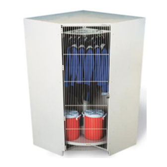
Corner Cabinet and Options
Printed in USA 08/14
Assembly Instructions
Part #250A893-05
Advertisement
Chapters
Table of Contents

Subscribe to Our Youtube Channel
Related Manuals for Wenger Corner Cabinet


Summary of Contents for Wenger Corner Cabinet
- Page 1 Corner Cabinet Assembly Instructions ........
- Page 2 Wenger Corporation. Wenger Corporation does not assume any responsibility for any errors that may appear in this manual. In no event will Wenger Corporation be liable for technical or editorial omissions made herein, nor for direct, indirect, special, incidental, or consequential damages resulting from the use or defect of this manual.
-
Page 3: Table Of Contents
Corner Cabinet Fasteners Parts List ........ - Page 4 The Wenger Corner Cabinet is intended for indoor use in normal ambient temperature and humidity conditions — it must not be exposed to prolonged outside weather conditions. • The Wenger Corner Cabinet is intended to be permanently installed only as described in this manual. ORNER ABINET...
- Page 5 Filler Strips (one long/one short) that all required hardware is present. Discard any Deflector Panel* items not used during the assembly. * Use only with Revolving Options NOTE: Depending on Corner Cabinet configuration, hole positioning in the individual panels may vary.
-
Page 6: Corner Cabinet Assembly
Outside Surface Screw Insert, -20 x " (9) Clearance Hole Screw Insert, -20 x " (9) (Install these only with Revolving Shelf Option) Top Panel (19) NOTE: Depending on Corner Cabinet configuration, hole positioning in the individual panels may vary. - Page 7 10. Using the mallet, drive two Tack Glides (3) into the bottom surface of the Left Hand Back Panel (18) as shown below. Each Tack Glide (3) should be about 1 " from the corner. NOTE: Depending on Corner Cabinet configuration, hole positioning in the individual panels may vary. Tack Glide (3)
- Page 8 ORNER ABINET SSEMBLY ONTINUED 11. Place the Right Hand Back Panel (17) flat on the floor with the inside surface facing down. IMPORTANT: When the Right Hand Back Panel has the inside surface facing down, there are five pilot holes on the right hand edge and the three Dowel holes at the top of the panel are visible when viewing it from the top edge (refer to the illustration below).
- Page 9 17. Using a mallet, drive the Screw Inserts (8) into the ” clearance holes in the Right Hand Side Panel (15) as shown below (Shelf/Hanger Bar option shown). NOTE: Depending on Corner Cabinet configuration, hole positioning in the individual panels may vary. Bottom Edge of Panel Outside Surface...
- Page 10 20. Using the mallet, drive two Tack Glides (3) into the bottom surface of the Right Hand Side Panel (15) about 1 ” from each bottom corner as shown below. NOTE: Depending on Corner Cabinet configuration, hole positioning in the individual panels may vary. Tack Glide (3) Drive Glide into bottom surface about 1”...
- Page 11 23. Using a mallet, drive twelve Screw Inserts (8) into the ” clearance holes in the Left Hand Side Panel (16) as shown below. NOTE: Depending on Corner Cabinet configuration, hole positioning in the individual panels may vary. Screw Insert, 8-32 x " (8)
- Page 12 26. Using the mallet, drive two Tack Glides (3) into the bottom surface of the Left Hand Side Panel (16) about 1 ” from each bottom corner as shown below. NOTE: Depending on Corner Cabinet configuration, hole positioning in the individual panels may vary. Tack Glide (3) Drive Glide into bottom surface about 1”...
- Page 13 Pilot Hole Clearance Hole Hex Lag Screw (7) Right Hand Back Panel (17) Left Hand Back Panel (18) Pilot Holes Clearance Hole Hex Lag Screw (7) NOTE: Depending on Corner Cabinet configuration, hole positioning in the individual panels may vary.
- Page 14 ORNER ABINET SSEMBLY ONTINUED 29. With two people working together, attach the Right Hand Side Panel (15) to the two assembled Back Panels, keeping the panels vertical as shown below. 30. Using the Hex Insert Bit (13), connect the Right Hand Side Panel (15) to the Right Hand Back Panel (17) with five Hex Lag Screws (7).
- Page 15 ORNER ABINET SSEMBLY ONTINUED 31. With two people working together, attach the Left Hand Side Panel (16) to the two assembled Back Panels keeping them vertical as shown below. 32. Using the Hex Insert Bit (13), attach the Left Hand Side Panel (16) to the Left Hand Back Panel (18) with five Hex Lag Screws (10).
- Page 16 ORNER ABINET SSEMBLY ONTINUED 33. Make sure that the Hex Lag Screws (7) holding the two Side Panels to the two Back Panels are loosened. 34. Carefully place the Top Panel (19) onto the Back Panels aligning the Wood Dowels (4) in the two Back Panels to the dowel pilot holes on the inside surface of the Top Panel.
- Page 17 ORNER ABINET SSEMBLY ONTINUED 37. Attach a Trim Strip (12) to the Left Hand Side Panel (16) and the Right Hand Side Panel (15) using a Pan Head Screw, 1 ” long (11) for each Trim Strip as shown in the illustration below. Left Hand Side Panel (16) Trim Strip (12) Pan Head Screw,...
- Page 18 SSEMBLY ONTINUED 38. Install the Upper Frame (21) inside the upper part of the Corner Cabinet by doing the following. a. Hold the Upper Frame in position as shown below. b. Using the Hex Insert Bit (13), fasten the Upper Frame to the Top Panel (19) with six Hex Socket Machine Screws (10).
- Page 19 ORNER ABINET SSEMBLY ONTINUED 39. Fasten five Leveler Glides (5) to the Bottom Frame (20) using a " open end wrench as shown below. Screw the Leveler Glide into the Bottom Frame until the head of the Leveler Glide is against the Bottom Frame Weld Nut.
- Page 20 SSEMBLY ONTINUED 41. Install the Bottom Frame (20) inside the lower part of the Corner Cabinet by doing the following. a. Hold the Bottom Frame (20) in position as shown below. b. Using the Hex Insert Bit (13), fasten the Bottom Frame to the Right Hand Back Panel (17) and Left Hand Back Panel (18) with six Hex Socket Machine Screws (10) as shown below.
-
Page 21: Level The Cabinet
EVEL THE ABINET 1. Check the level of the entire floor where the Corner Cabinet will be installed. Determine the highest point of the floor in that area. Extend all Leveler Glides until the bottom of the cabinet is higher than the highest point in the floor (so that the bottom of cabinet is not touching the floor). -
Page 22: Assemble Cabinet Connector Bracket
ONNECTOR RACKET 1. Place the Corner Cabinet in its final position against a wall or surface that will serve as an anchor for the cabinet. 2. Using the Cabinet Connector Bracket (19) as a template, mark the position for the four holes to mount the bracket. -
Page 23: Door Assembly Parts List
X001767 Hinge, Wood Door 250A505._ Pan Head Screw, painted 250A511._ Door Catch, Full Length 145R475 Flat Head Screw, painted 250A509._ Door Stop, Corner Cabinet 250A535._ Screw Insert, 8-32 x " Hex Insert Bit, " 250A506._ X001962 Flat Head Screw, painted 250A507._... - Page 24 NOTE: Make sure that the cabinet is level before assembling the door. Item Description Item Description Door Stop Cabinet Door Catch Full Length Handle, Wood Full Door Door Stop, Corner Cabinet Latch Assembly, Full Wood Door Door, Full Hinge Wood Door Cabinet Bracket...
-
Page 25: Wood Door Assembly
SSEMBLY ONTINUED SSEMBLY 1. Assemble the Screw Inserts (6) to the Wood Door (16) as follows. a. Place the Wood Door (16) on the floor with the outside surface facing upward. b. Using a mallet, drive eight Screw Inserts (6) into the eight clearance holes in the Door as shown below. - Page 26 SSEMBLY ONTINUED SSEMBLY C ONTINUED 2. Assemble the Wood Door Hinges (12) to the Wood Door as follows. a. Lay the Wood Door flat with the inside surface facing upward (heads of the Screw Inserts, installed in step 1, are on the outside surface and must face downward). b.
- Page 27 SSEMBLY ONTINUED SSEMBLY C ONTINUED 3. Assemble the Wood Door Latch Assembly (11) and Wood Door Handle (10) to the Wood Door (16) as follows. a. Insert the two Wood Door Latch Assembly Threaded Post (11) into the two clearance holes on the outside surface of the Door as shown below.
- Page 28 SSEMBLY ONTINUED SSEMBLY C ONTINUED 4. Install the Door Catch (13) to the inside (lower) surface of the Top Panel by inserting two Pan Head Screws (1) through the clearance holes in the Catch and into the two Pilot Holes in the inside surface of the Top Panel.
- Page 29 5. Assemble the Door Stop to the Right Hand Side Panel as follows. a. Assemble the Cabinet Door Stop (9) to the Corner Cabinet Door Stop (14) with two Lock Washer Hex Nuts (2) and two Truss Head Screws (3) (Corner Cabinet Door Stop color matches Hinge color).
- Page 30 6. Attach the Wood Door (16) to the Corner Cabinet as follows. a. Align the Wood Door to the Corner Cabinet so that the mounting holes in each Wood Door Hinge (12) align to the clearance holes in the Left Hand Side Panel with screw inserts.
-
Page 31: Grille Door Assembly
1. Assemble the Grille Door Stop as follows. a. Attach the Cabinet Door Stop (9) to the Corner Cabinet Door Stop (14) with two Lock Washer Hex Nuts (2) and two Truss Head Screws (3) (Corner Cabinet Door Stop color matches Hinge color). - Page 32 2. Attach the Grille Door (16) to the Corner Cabinet as follows. a. Align the Grille Door (16) to the Corner Cabinet so that the mounting holes in each Grille Door Hinge aligns to the clearance holes in the Left Hand Side Panel with screw inserts.
- Page 33 Shelf/Hanger Bar Option Assembly Instructions Corner Cabinet with a Fixed Shelf Corner Cabinet with Hanger Bars ONTENTS Important User Information ...........34 Shelf/Hanger Bar Required Tools .
-
Page 34: Important User Information
The Wenger Corner Cabinet Shelf/Hanger Bar is intended to be permanently installed only as described in this manual. • HELF ANGER EQUIRED OOLS The following tools must be supplied by the installer to install the Wenger Corner Cabinet Shelf/Hanger bar: Variable Speed Drill Philips Screwdriver • HELF ANGER ARTS LIST •... -
Page 35: Shelf/Hanger Bar Assembly
HELF ANGER SSEMBLY Before starting the Shelf/Hanger Bar assembly, do the following. 1. Read and understand this assembly instruction. 2. Remove all items from the shipping carton and make sure that all parts are present. Item numbers refer to the Part List above and the table below. 3. -
Page 36: Fixed Shelf Assembly
HELF ANGER SSEMBLY ONTINUED IXED HELF SSEMBLY To install a Shelf, do as follows. 1. Align one of the Shelf Supports (7) to the " diameter clearance holes on the inside surface of the Left Hand Back Panel next to the Right Hand Side Panel as shown below. Orient the Tabs to face away from the Back Panel. - Page 37 HELF ANGER SSEMBLY ONTINUED IXED HELF SSEMBLY C ONTINUED 4. To install an upper Shelf (6), do as follows. a. Place the Shelf (6) on the Shelf Supports (7). b. Align the three clearance holes in the front Shelf Support (7) with the three pilot holes on the front bottom side of the Shelf (6).
-
Page 38: Band Uniform Hanger Bar Assembly
HELF ANGER SSEMBLY ONTINUED NIFORM ANGER SSEMBLY To install the Hanger Bars (8) for Uniform Storage, do as follows. 1. Align the clearance holes in the end of a Hanger Bars (8) to the upper pair of " diameter clearance holes in the Left Hand Back Panel and the Right Hand Side Panel. -
Page 39: Choral Robe Hanger Assembly
HELF ANGER SSEMBLY ONTINUED HORAL ANGER SSEMBLY To install the Hanger Bar (8) for Choral Robes, do as follows. 1. Align the clearance holes in the end of a Hanger Bar (8) to the mid-pair of " diameter clearance holes (13" below the upper set of holes) in the Left Hand Back Panel and the Right Hand Side Panel. - Page 40 This page is intentionally blank.
- Page 41 Revolving Shelf Option Assembly Instructions Corner Cabinet Revolving Shelf Option Corner Cabinet Flag Storage Option shown shown with six Half Shelf Assemblies with four Flag/Robe Assemblies and two Half Shelf Assemblies ONTENTS Important User Information ...........42 Revolving Shelf Required Tools .
-
Page 42: Important User Information
• EVOLVING HELF EQUIRED OOLS The following tools must be supplied by the installer to install the Wenger Corner Cabinet Revolving Shelf: Philips Screwdriver ” Socket and Ratchet Adjustable Wrench ” and ” sockets are optional) •... - Page 43 EVOLVING HELF SSEMBLY Before starting assembly of the Corner Cabinet Revolving Options, do the following. 1. Read and understand this assembly instruction. 2. Remove all items from the shipping carton and arrange the parts as shown in the diagram below.
-
Page 44: Assemble Deflector Panel To The Corner Panel
ORNER ANEL To assemble the Deflector Panel (8) to the Corner Cabinet, do as follows. 1. Place the Deflector Panel (8) against the Right Hand Back Panel and the Left Hand Back Panel. 2. Align the 14 Clearance Holes in the Deflector Panel (8) to the seven Pilot Holes in the Right Hand Back Panel and the seven Pilot Holes in the Left Hand Back Panel. -
Page 45: Assemble Base Frame And Center Column
EVOLVING HELF SSEMBLY ONTINUED SSEMBLE RAME AND ENTER OLUMN 1. Assemble the Leveler Glides (14) to the Base Frame Assembly (10) as follows. a. Screw four Leveler Glides (14) into the lower surface of the four -16 threaded holes in the Base Frame Assembly (10). - Page 46 EVOLVING HELF SSEMBLY ONTINUED SSEMBLE RAME AND ENTER OLUMN C ONTINUED 2. Assemble the Base Frame Assembly (10), Center Column (11), and Top Plate Assembly (9) as follows. a. Place the Base Frame Assembly (10) flat on the floor. b. Place the Thrust Washer (6) onto the Base Frame Assembly Post (10). c.
- Page 47 With two people working together, slide the Base Frame, Center Column and Top Plate (assembled together) through the doorway into the Corner Cabinet. It may be necessary to rotate the Base Frame Assembly as it is pushed through the doorway.
-
Page 48: Assemble A Half Shelf To The Center Column
EVOLVING HELF SSEMBLY ONTINUED SSEMBLE A HELF TO THE ENTER OLUMN To install the Half Shelf Assembly to the Center Column Assembly, do as follows. 1. Place the Half Shelf Assembly (12) against the Center Column Assembly (11), aligning the Clearance Holes in the Half Shelf with the Clearance Holes in the Center Column. -
Page 49: Assemble A Flag/Choral Robe Pack
EVOLVING HELF SSEMBLY ONTINUED SSEMBLE A HORAL 1. Assemble two Flag/Choral Robe Assemblies (13) to the Center Column (11) as follows. Refer to page 51 for the placement of the Flag/ Choral Robe Assemblies. NOTE: If you are assembling a Flag Storage Option, install the Flag/Choral Robe Assemblies (13) five feet above the Revolving Shelf (12). - Page 50 EVOLVING HELF SSEMBLY ONTINUED ASSEMBLE FLAG CHORAL ROBE PACK ( CONTINUED 2. To assemble the second pair of Flag/Choral Robe Assemblies (13), do as follows. a. Place a Flag/Choral Robe Assembly (13) against the Center Column Assembly (11) between the two assembled Flag/Choral Robe Assemblies with the upper edge even with the other assemblies(refer to the illustration below).
- Page 51 EVOLVING HELF SSEMBLY ONTINUED ASSEMBLE FLAG CHORAL ROBE PACK ( CONTINUED 3. If you are assembling a Flag Storage Option, locate the Flag/Choral Robe Assembly (13) five feet above the Half Shelf Assemblies (12) and place a Pad on the upper surface of each Half Shelf Assembly (12) as shown below.
- Page 52 This page is intentionally blank.
Need help?
Do you have a question about the Corner Cabinet and is the answer not in the manual?
Questions and answers