Prolon M2000 Series Hardware Manual
Heatpump controller
Hide thumbs
Also See for M2000 Series:
- Hardware manual (21 pages) ,
- Quick start manuals (16 pages) ,
- Technical reference manual (98 pages)

Related Manuals for Prolon M2000 Series


Summary of Contents for Prolon M2000 Series
- Page 1 Hardware Guide Heatpump Controller M2000 Series Specifications and Operational Guide www.proloncontrols.com info@proloncontrols.com REV 6.3 PL-HRDW-M2000HP-C/W-EN-V63...
-
Page 2: Table Of Contents
PL-M2000 SERIES HEATPUMP HARDWARE GUIDE www.proloncontrols.com Table of Contents GENERAL INFORMATION ......................3 PL-M2000 Heatpump Controller ........................3 Description ................................... 3 General Behaviour ............................... 3 Operating Sequence ............................. 4 General ..................................4 Occupied Mode ................................4 Unoccupied Mode ................................ 5 COMPONENTS .......................... -
Page 3: General Information
General Behaviour Although fully configurable, the ProLon M2000 Heatpump controller uses pre-established control sequences or ’’profiles’’ to operate specific HVAC equipment with dedicated output functions. These can be fully optimized to obtain the best results for each type of system. Numerous parameters enable the... -
Page 4: Operating Sequence
Operating Sequence General The ProLon M2000 Heatpump controller receives readings from three different temperature sensors: outside air, return air and supply air. It operates on a configurable schedule using an internal real-time clock. Also, as a Master device, it receives data from the zone controllers sent on the network bus. The... -
Page 5: Unoccupied Mode
PL-M2000 SERIES HEATPUMP HARDWARE GUIDE www.proloncontrols.com Unoccupied Mode The fan can be configured to operate in intermittent mode. When there is a cooling or heating demand from any single zone, the Rooftop controller will activate the fan and the necessary cooling or heating outputs as long as all temperature limits, delays and other related parameter are respected. -
Page 6: Components
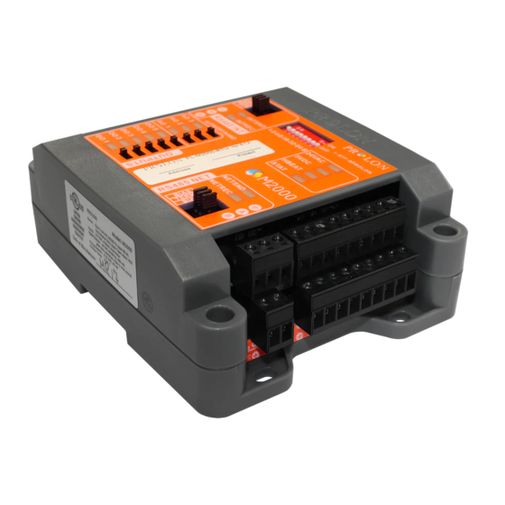
PL-M2000 SERIES HEATPUMP HARDWARE GUIDE www.proloncontrols.com COMPONENTS Component Identification Legend: A = Addressing Dipswitch B = AUTO/OFF/HAND Switches C = RS485 INT port for interface communication (RJ45 plug and screw connectors are in parallel) D = Analog outputs (3) E = Digital outputs (5) -
Page 7: Leds And Switches
HBEAT: When this LED is blinking, the microchip is active and the controller’s program is • running (normal). When this LED is ON and steady, the M2000 is inactive and the microchip is awaiting programming (you must use ProLon’s Focus software to reprogram the microchip). STAT: Reserved. •... -
Page 8: Hand/Off/Auto Switches
PL-M2000 SERIES HEATPUMP HARDWARE GUIDE www.proloncontrols.com AO1: The intensity of the LED represents the voltage present on analog output 1. • DO5: Represents the activity of digital output 5. • DO4: Represents the activity of digital output 4. • DO3: Represents the activity of digital output 3. -
Page 9: Jumpers
Figure 2: Location of the INTERNAL jumpers INT: These are the jumpers for the bias and terminating resistors used for the interface communication bus. See the ProLon network guide for information about bias and terminating resistors. NET: These are the jumpers for the bias and terminating resistors used for the network communication bus. -
Page 10: Input And Output Identification
PL-M2000 SERIES HEATPUMP HARDWARE GUIDE www.proloncontrols.com Input and Output Identification All the inputs and outputs of the M2000 use pluggable screw type terminal blocks with elevator style clamping, which make connections easier and more secure. For incoming communication from a remote computer or network controller, dual RJ45 type connectors are available in parallel with screw type terminal blocks. -
Page 11: Addressing Dipswitch Configuration For Network Communication
The example in Figure 3 shows the switches 1, 2 and 4 in the ON position. Therefore, the corresponding values are 1, 2 and 8, giving an address sum of 11. The ProLon network allows a maximum of 127 addresses; therefore 127 controllers. Figure 3: Addressing Dipswitch Montréal... -
Page 12: Inputs
PL-M2000 SERIES HEATPUMP HARDWARE GUIDE www.proloncontrols.com INPUTS Temperature Sensors The M2000 Heatpump controller has three analog inputs that monitor outside air, supply air and return air temperatures (see Figure 4) and will integrate these readings into its control sequence. The sensors used are standard 10k type thermistors that share a single common connection. -
Page 13: Room Sensors
PL-M2000 SERIES HEATPUMP HARDWARE GUIDE www.proloncontrols.com Room Sensors The M2000 can receive the setpoint and temperature from a specific room when a PL-RS analog thermostat is connected to it. The M2000 will then automatically integrate this information into its control sequence. -
Page 14: Dry Contact For Clogged Filter Or Schedule Override
PL-M2000 SERIES HEATPUMP HARDWARE GUIDE www.proloncontrols.com Dry Contact for Clogged Filter or Schedule Override Analog input 4 on the M2000 can also be configured as a dry contact input for either a clogged filter sensor or as a schedule override input. Please refer to Figure 7 to see proper connection. -
Page 15: Static Pressure And Co
PL-M2000 SERIES HEATPUMP HARDWARE GUIDE www.proloncontrols.com Static Pressure and CO Analog inputs 8 and 9 on the M2000 heatpump controller are dedicated to the CO and static pressure sensors, respectively. By default, a 4-20 mA signal is expected for the CO input and a 0-5 VDC or 1-5 VDC signal is expected for the static pressure input. -
Page 16: Outputs
The M2000 Heatpump controller contains 8 customizable outputs; five triac ON/OFF outputs (24VAC) and three analog outputs (0-10VDC). Output configuration is performed via the ProLon Focus software. An integrated resettable fuse protects each of the outputs of the M2000 against current surges and short circuits. -
Page 17: Typical Connection Of Triac Outputs 1 To 5
PL-M2000 SERIES HEATPUMP HARDWARE GUIDE www.proloncontrols.com Typical Connection of Triac Outputs 1 to 5 On the M2000 Heatpump controller, all triac outputs produce a 24 VAC live voltage when activated. Note that all output voltages originate from a single voltage supply: the equipment’s transformer. -
Page 18: Power Source & Network
Figure 12: Connecting the 24VAC power source Network Communication The ProLon M2000 Heatpump controller is designed to work with the ProLon zone controllers (except Heatpump Standalone controller). When they are networked, the M2000 and zone controllers all communicate in real-time. The network connections are made using the network terminal block located on the M2000 controller (see Figure 13). -
Page 19: Technical Specifications
Dimensions: 137 mm x 112 mm ( 5.39" x 4.41" ) Environment: 0-50 ºC (32-122 ºF) Non-Condensing The performance specifications are nominal and conform to acceptable industry standards. ProLon Inc. will not be liable for damages resulting from misapplication or misuse of its products. -
Page 20: Compliance
Caution: Any changes or modifications not approved by ProLon can void the user’s authority to operate the equipment. Note: This equipment has been tested and found to comply with the limits for a Class B digital device, pursuant to part 15 of the FCC Rules. -
Page 21: Overall Dimensions
No part of this document may be photocopied or reproduced by any means, or translated to another language without prior written consent of ProLon. All specifications are nominal and may change as design improvements are introduced. ProLon shall not be liable for damages resulting from misapplication or misuse of its products.
Need help?
Do you have a question about the M2000 Series and is the answer not in the manual?
Questions and answers