Prolon M2000 Series Hardware Manual
Fan coil controller
Hide thumbs
Also See for M2000 Series:
- Hardware manual (21 pages) ,
- Quick start manuals (16 pages) ,
- Technical reference manual (98 pages)

Subscribe to Our Youtube Channel
Related Manuals for Prolon M2000 Series


Summary of Contents for Prolon M2000 Series
- Page 1 HARDWARE GUIDE Fan Coil Controller M2000 Series Specifications and Operational Guide www.proloncontrols.com | info@proloncontrols.com 17 510, rue Charles, Suite 100, Mirabel, QC, J7J 1X9 REV. 7.4.0 PL-HRDW-FCU-M2000-C/F-EN...
-
Page 2: Table Of Contents
Table of Contents General Information ............................... 4 PL-M2000 Fan Coil Controller ..................................4 Description ..........................................4 General Behavior ........................................4 Operating Sequence ............................... 5 Fan ............................................5 Two-Pipe System.........................................5 Four Pipe System ........................................5 Components ..................................6 Component Identification ....................................6 LEDs and Switches ......................................7 HAND/OFF/AUTO Switches .....................................8 Jumpers ..........................................8 Input and Output Identification ..................................9 Addressing Dipswitch Configuration for Network Communication ..................... - Page 3 Table of Figures Figure 1 - Component Identification ..................................6 Figure 2 - LEDs Identification ....................................7 Figure 3 - Location of the EXTERNAL jumpers ...............................8 Figure 4 - Location of the INTERNAL jumpers ..............................8 Figure 5 - INT and NET jumpers ...................................8 Figure 6 - AI jumpers ........................................8 Figure 7 - RJ45 Pinout ......................................9 Figure 8 - Input and Output Identification (Two-Pipe System).........................9...
-
Page 4: General Information
Two-Pipe or Four-Pipe configurations. Additional backup reheat and preheat sequences can activate to heat the air as required. When networked with other Prolon devices, the FCU controller can periodically share its status to a Master controller and help drive the direction of the whole system. -
Page 5: Operating Sequence
The water supply temperature can be obtained via a local thermistor input, a dry contact or shared via the Prolon Network. In the case of a local thermistor, a purge cycle is available to periodically flush out stagnant water and update the water supply mode. -
Page 6: Components
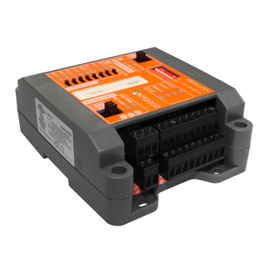
Components Component Identification Figure 1 - Component Identification Legend: A - Addressing Dipswitch B - AUTO/OFF/HAND Switches C - RS485 INT port for interface communication (RJ45 plug and screw connectors are in parallel) D - Analog outputs (3) E - Digital outputs (5) F - Analog inputs (9) G - RS485 NET port for network communication H - Terminal block for 24VAC (Class 2 transformer) -
Page 7: Leds And Switches
When this LED is ON and steady, the M2000 is inactive present on analog output 1. and the microchip is awaiting programming (you must use Prolon’s Focus software to reprogram the • DO5: Represents the activity of digital output 5. microchip). -
Page 8: Hand/Off/Auto Switches
• INT: These are the jumpers for the bias and terminating resistors used for the interface communication bus. See the Prolon network guide for information about bias and terminating resistors. (See Figure 5) • NET: These are the jumpers for the bias and terminating resistors used for the network communication bus. See the Prolon network guide for information about bias and terminating resistors. -
Page 9: Input And Output Identification
The M2000 Fan Coil Controller has 2 separate communication ports offering the same functionality on each. Both act as ports for incoming Modbus communications from other Prolon devices or interfaces, such as a Network Controller or remote computer with Prolon Focus software. -
Page 10: Addressing Dipswitch Configuration For Network Communication
The example in Figure 10 shows the switches 1, 2 and 4 in the ON position. Therefore, the corresponding values are 1, 2 and 8, giving an address sum of 11. The Prolon network allows a maximum of 127 addresses; therefore 127 controllers. Figure 10 - Addressing Dipswitch... -
Page 11: Inputs
The outside air and two pipe coil water supply temperatures can also be provided by an alternate source on the Prolon network. If a network or master controller is present, they can relay these reading from one controller to another. -
Page 12: Proof Of Fan
Proof of Fan The M2000 Fan Coil has an analog input dedicated to the proof of fan signal. Please refer to Figure 13 to see how to cor- rectly connect it to analog input 7. To indicate proof of fan, the contact must be closed. Proof of Fan Figure 13 - Connecting the Proof of Fan Contact to the Controller Room Sensors... -
Page 13: Digital Room Sensors
Digital Room Sensors Prolon offers various digital communicating sensors that can provide the M2000 with room temperature, room setpoint, and schedule override (T1000, T500, T200 sensors). Typical wiring is as follows: 4 Conductor Cable Digital Sensor M2000 Power Source (24VAC -Class 2) Figure 15 - Connecting the Digital Sensor to the Controller REV. -
Page 14: Outputs
The M2000 Fan Coil controller has 8 configurable outputs: 5 Triac type 24VAC outputs and 3 analog outputs (0-10VDC, voltage or pulse width modulation, On-or-Off). Output configuration is performed via the Prolon Focus software. An integrated resettable fuse protects each of the outputs of the M2000 against current surges and short circuits. This protection will cut the current to the output as soon as an overload condition is detected. -
Page 15: Typical Connection The Digital Outputs
Typical Connection the Digital Outputs On the M2000 Fan Coil controller, all triac outputs produce a 24 VAC live voltage when activated. Note that all output voltages originate from a single voltage supply: the equipment’s transformer. Consequentially, only the live side of the output connections are usually needed;... -
Page 16: Power Source & Network
Figure 18 - Connecting the 24VAC Power Source Network Communication The Prolon M2000 Fan Coil controller is designed to work standalone or networked with Prolon master controllers. When networked, the master transmits the occupancy status, outside temperature and math demand in real-time. The network connections are made using the network terminal block located on the M2000 controller. -
Page 17: Technical Specifications
Certification: UL916 Energy Management Equipment, CAN/CSA-C22.2, RoHS, FCC part 15: 2012 class B The performance specifications are nominal and conform to acceptable industry standards. Prolon Inc. will not be liable for damages resulting from misapplication or misuse of its products. -
Page 18: Compliance
Caution: Any changes or modifications not approved by Prolon can void the user’s authority to operate the equipment. Note: This equipment has been tested and found to comply with the limits for a Class B digital device, pursuant to part 15 of the FCC Rules. -
Page 19: Overall Dimensions
No part of this document may be photocopied or reproduced by any means, or translated to another language without prior written consent of Prolon. All specifications are nominal and may change as design improvements are introduced. Prolon shall not be liable for damages resulting from misapplication or misuse of its products.
Need help?
Do you have a question about the M2000 Series and is the answer not in the manual?
Questions and answers