CyberData 010845 Operation Manual
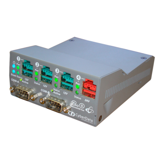
4-port poweredusb 2.0 hub with serial ports and external power supply
Hide thumbs
Also See for 010845:
- Operation manual (22 pages) ,
- Manual (24 pages) ,
- Quick reference (2 pages)
Table of Contents

Related Manuals for CyberData 010845


Summary of Contents for CyberData 010845
- Page 1 The IP Endpoint Company Operations Guide for the 4-Port PoweredUSB 2.0 Hub with Serial Ports and External Power Supply Part #010845 Document Part #930105E CyberData Corporation 3 Justin Court Monterey, CA 93940 (831) 373-2601...
- Page 2 CyberData Corporation. This manual, and the products, software, firmware, and/or hardware described in this manual are the property of CyberData Corporation, provided under the terms of an agreement between CyberData Corporation and recipient of this manual, and their use is subject to that agreement and its terms.
- Page 3 Revision Information Revision 930105E was updated on August 15, 2018 and has the following changes: • Adds Section 1.1, "How to Identify This Product". • Adds Section 1.3, "Specifications". • Adds Section 1.4, "Compliance". Operations Guide 930105E CyberData Corporation...
- Page 4 Electrical Hazard: This product should be installed by a licensed electrician according to all local electrical and building codes. GENERAL ALERT Warning Electrical Hazard: To prevent injury, this apparatus must be securely attached to the floor/wall in accordance with the installation instructions. GENERAL ALERT Operations Guide 930105E CyberData Corporation...
- Page 5 Potential safety hazards are identified in this manual through the use of words Danger, Warning, and Caution, the specific hazard type, and pictorial alert icons. Operations Guide 930105E CyberData Corporation...
-
Page 6: Table Of Contents
2.3.2 Host connector .......................7 2.3.3 Jumpers ..........................8 2.3.4 PoweredUSB Connections .....................8 2.3.5 Connector Color Keys ....................9 2.3.6 Peripherals connections to the CyberData 4-Port PoweredUSB 2.0 Hub ....10 2.3.7 Peripheral cable connection options ................10 2.4 Operation ..........................13 2.5 Port Electrical Specifications ....................14... -
Page 7: Chapter 1 Product Overview
To identify the PoweredUSB Hub, look for a model number label similar to the one shown in Figure 1- 1. Confirm the following: • The model number on the label should be 010845. • The serial number on the label should begin with 845. Figure 1-1. Model Number Label... -
Page 8: Product Features
Directive – EN 60950-1, RoHS Compliant, FCC; Part 15 Class A, Industry Canada; ICES-3 Class A, IEEE 802.3 Compliant Part Number 010845 a. All ports support standard "A" type +5V USB connection. b. Dimensions are measured from the perspective of the product being upright with the front of the product facing you. -
Page 9: Compliance
® CyberData Corporation is licensed with IBM to manufacture, and to sell or lease products that incorporate this technology. This license also permits other entities to resell or release these Cyberdata products after they have been purchased from CyberData. -
Page 10: Chapter 2 Installing And Using The 4-Port Poweredusb Hub
2 Installing and Using the 4-Port PoweredUSB Hub This chapter provides the instructions, illustrations, and background information you need to install, and begin working with the CyberData 4-Port PoweredUSB 2.0 Hub with Serial Ports. 2.1 Product Components List The PoweredUSB Hub package includes these parts: •... -
Page 11: Component Identification
Cable strain relief 2.1.2 Product Compatibility The CyberData 4-Port PoweredUSB 2.0 Hub is compatible with the following operating systems and USB standards. Operating systems Windows 2000 and XP 2.0 Standard LINUX PoweredUSB 0.8g... -
Page 12: Installation
Installing and Using the 4-Port PoweredUSB Hub Installation 2.2 Installation The CyberData 4-Port PoweredUSB 2.0 Hub is a tabletop unit with mounting feet that sit on a flat surface. 2.3 Connections This following topics provide illustrations and information on connecting the CyberData 4-Port PoweredUSB 2.0 Hub to power supplies, the host, and peripheral devices. -
Page 13: Host Connector
“B” cable that is included in the Accessory Kit, or with any equivalent USB 2.0 certified Hi-Speed cable. Refer to Section 2.1, "Product Components List" for information about the Accessory Kit. Figure 2-3. Host Connector with Strain Relief Operations Guide 930105E CyberData Corporation... -
Page 14: Jumpers
The PoweredUSB connections are standard USB “A” connectors with four extra pins to supply higher voltages. See Figure 2-6 for an illustration. The lower portion of the “A” connector side on this product can be used alone, without the locking PoweredUSB connector. Operations Guide 930105E CyberData Corporation... -
Page 15: Connector Color Keys
Figure 2-6. USB PoweredUSB Socket Connector Pin Assignments PIN OUT Signal Description Vbus USB standard “A” USB standard “A” USB standard “A” Ground USB standard “A” Ground USB PlusPower Vplus USB PlusPower Vplus USB PlusPower Ground USB PlusPower Shell Shield Operations Guide 930105E CyberData Corporation... -
Page 16: Peripherals Connections To The Cyberdata 4-Port Poweredusb 2.0 Hub
Installing and Using the 4-Port PoweredUSB Hub Connections 2.3.6 Peripherals connections to the CyberData 4-Port PoweredUSB 2.0 Hub This figure illustrates the cable routing from the CyberData 4-Port PoweredUSB 2.0 Hub to the Dell Retail Integrator. Figure 2-7. Top view of Hub PoweredUSB cable routing... - Page 17 Installing and Using the 4-Port PoweredUSB Hub Connections CyberData PoweredUSB Cables Figure PoweredUSB Cable Description CyberData Part Number Figure 2-8 12V to 2x4 010693C Figure 2-9 12V to 12V Power Jack Contact CyberData Figure 2-10 24V PoweredUSB to 3-Pin Power Mini-DIN...
- Page 18 Installing and Using the 4-Port PoweredUSB Hub Connections Figure 2-10. Cables; +24V PoweredUSB to 3-Pin Mini-DIN and RS-232 to RS-232 or Parallel to Parallel Figure 2-11. “Y” Cable, +24V PoweredUSB to 3-Pin Power Mini-DIN and USB “B” Connectors Operations Guide 930105E CyberData Corporation...
-
Page 19: Operation
Figure 2-14. RS232 to USB Converter “Y” Cable +24V 2.4 Operation The CyberData 4-Port PoweredUSB 2.0 Hub is a standard USB Hub that complies with the USB 2.0 specification, and adds PoweredUSB ports. When connected to a Host, it is enumerated as a Generic USB Hub. -
Page 20: Port Electrical Specifications
Section B.3, "Contact Information". 2.5 Port Electrical Specifications The CyberData 4-Port PoweredUSB 2.0 Hub adheres to the USB 2.0 electrical specifications as follows: Standard USB Each lower portion of the PoweredUSB port provides +5V @ 500mA. If more than 500mA are drawn... -
Page 21: Appendix A Setting Up The Hub On Windows Xp
Appendix A: Setting up the Hub on Windows XP For connecting the CyberData 4-Port PoweredUSB 2.0 Hub to a PC running the Windows XP operating system, keep in mind: 1. Microsoft XP Service Pack 1 or higher must be installed. -
Page 22: Appendix B Troubleshooting/Technical Support
To see a list of frequently asked questions for your product, click on the FAQs tab at the following webpage: https://www.cyberdata.net/collections/poweredusb/products/010845 B.2 Documentation The documentation for this product is released in an English language version only. To download PDF copies of CyberData product documentation, click on the Downloads tab at the following webpage: https://www.cyberdata.net/collections/poweredusb/products/010845 Operations Guide 930105E... -
Page 23: Contact Information
Support form at the following website: http://support.cyberdata.net/ The Support Form initiates a ticket which CyberData uses for tracking customer requests. Most importantly, the Support Form tells us which PBX system and software version that you are using, the make and model of the switch, and other important information. This information is essential for troubleshooting. - Page 24 5 jumpers 8 components list 4 connector color keys 9 contact information 17 contact information for CyberData 17 CyberData contact information 17 Microsoft XP Service Pack 1 15 DC input jacks 6 Dell printer power supply 6 part number 2...
- Page 25 17 technical support, contact information 17 2.0 specification 13 over current 14 warranty policy at CyberData 17 Windows XP 14, 15 Operations Guide 930105E CyberData Corporation...
Need help?
Do you have a question about the 010845 and is the answer not in the manual?
Questions and answers