
Related Manuals for CyberData 010630


Summary of Contents for CyberData 010630
- Page 1 The IP Endpoint Company PoweredUSB 6-Port 2.0 Hub Operations Guide Part #010630 Document Part #931035A CyberData Corporation 3 Justin Court Monterey, CA 93940 (831) 373-2601...
- Page 2 CyberData Corporation. This manual, and the products, software, firmware, and/or hardware described in this manual are the property of CyberData Corporation, provided under the terms of an agreement between CyberData Corporation and recipient of this manual, and their use is subject to that agreement and its terms.
- Page 3 Figure 1-7, "JP2 Connector with jumper ON" • Updates Section 1.3, "Features" • Updates Section 1.9, "JP2 Jumper Control Settings" • Updates Section 1.7.1.1, "Standard USB Lower A supply:" • Updates Section 1.7.1.2, "PoweredUSB Upper A supply:" Operations Guide 931035A CyberData Corporation...
- Page 4 Potential safety hazards are identified in this manual through the use of words Danger, Warning, and Caution, the specific hazard type, and pictorial alert icons. CyberData Corporation 931035A Operations Guide...
-
Page 5: Important Safety Instructions
To prevent injury, this apparatus must be securely attached to the floor/wall in accordance with the installation instructions. GENERAL ALERT Warning The PoE connector is intended for intra-building connections only and does not route to the outside plant. GENERAL ALERT CyberData Corporation 931035A Operations Guide... -
Page 6: Table Of Contents
1.9 JP2 Jumper Control Settings ....................8 1.9.1 Jumper OFF (Green mode) ....................8 1.9.2 Jumper ON ........................9 1.10 Regulatory ..........................10 1.10.1 License note: ......................10 1.10.2 Documentation Note: ....................10 1.10.3 Contact Information: ....................10 1.10.4 Safety .........................11 1.10.5 EMC ...........................11 Operations Guide 931035A CyberData Corporation... -
Page 7: Chapter 1 Product Overview
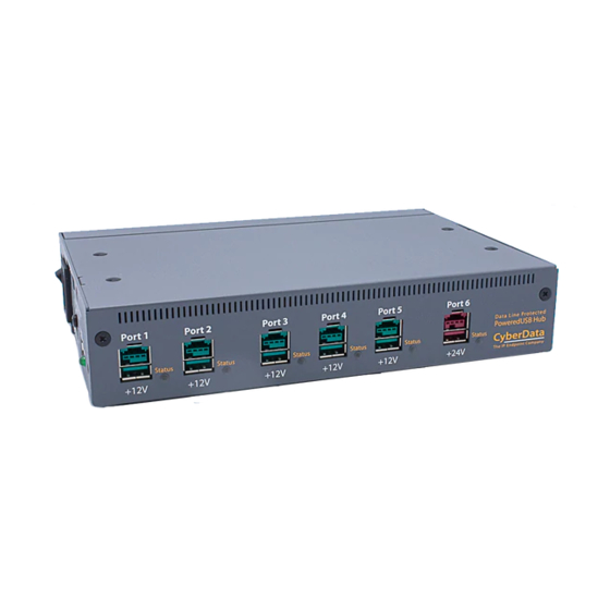
1 Product Overview 1.1 Product Description The CyberData PoweredUSB 6-Port 2.0 Hub provides a simple and affordable way to add up to six PoweredUSB ports to your PC that are controlled by the PC’s Stand-by/Wake commands. With this USB add-on, it is easy to connect devices that need more than the standard USB interface supplied 500mA of +5 volts. -
Page 8: External
Note The AC Power Cable is only supplied to US customers. User should use ONLY a suitable Power Supply cord that conforms to IEC 60320/C13. Operations Guide 931035A CyberData Corporation... -
Page 9: Installation
1.6.2.2 Host Connector The Host connector is a standard high-speed USB “A” to “B” type cable and can be procured from a variety of sources. Max length of 5 meters (16.4 feet) with good quality cable Operations Guide 931035A CyberData Corporation... -
Page 10: Usb Poweredusb Connections
The PoweredUSB connections are a standard “A” type connector with 4 extra pins designed to supply higher voltages. The “A” connector side of this product can be used, by itself, without the locking PoweredUSB connector being used. Operations Guide 931035A CyberData Corporation... -
Page 11: Connector Keying
The PoweredUSB connectors are keyed in such a way as to only allow the correct voltage cables to be installed. Figure 1-4. Connector Keying Picture with Color Coding Teal 12 Volt Keyed 24 Volt Keyed Ports 1 - 5 Port 6 Operations Guide 931035A CyberData Corporation... -
Page 12: Pin Out
USB PoweredUSB Shell Shield 1.6.6 PoweredUSB Cable Sources Custom and standard cable assemblies may be ordered from CyberData or they may be procured from other sources. For more information about the cables and connectors of PoweredUSB use the following link: www.poweredusb.org... -
Page 13: Operation
A two-pin jumper (JP2) located next to the power connector on the Printed Circuit Board controls this green feature. Please read the JP2 Jumper Control settings section below for details on controlling the standby feature. Operations Guide 931035A CyberData Corporation... -
Page 14: Jp2 Jumper Control Settings
Jumper JP2 controls the PC Stand-by/Wake Peripheral Control feature. Please refer to the Check- Off list shipped with your Hub for the factory set status of this jumper. If you need to change the jumper setting please contact CyberData for a addendum instruction on Hub case assembly/ disassembly. -
Page 15: Jumper On
LED light extinguishes and USB port LEDs light amber, +12V and +24V power to peripherals and power supply fan stay on, peripherals and Hub lose enumeration on PC. Figure 1-7. JP2 Connector with jumper ON Power connector JP2 Pin-1 and Pin-2 normally not jumpered Operations Guide 931035A CyberData Corporation... -
Page 16: Regulatory
"The PoweredUSB controller board contains certain technology covered by a patent held by IBM Corporation. Cyberdata has obtained a license from IBM that permits Cyberdata, among other things, to make and to sell or lease products that incorporate this technology. The license also permits these products to be resold or released by any entity after they have been initially sold by Cyberdata."... -
Page 17: Safety
UL62368-1 2nd Edition 1.10.5 EMC US/CAN Complies with: • Title 47 of the CFR, Part 15, Subpart B, Section 15.107(b) • Title 47 of the CFR, Part 15, Subpart B, Section 15.109 (b) • ICES-003 Operations Guide 931035A CyberData Corporation...
Need help?
Do you have a question about the 010630 and is the answer not in the manual?
Questions and answers