
Subscribe to Our Youtube Channel
Related Manuals for CyberData Hub


Summary of Contents for CyberData Hub
- Page 1 4-Port PoweredUSB 2.0 Hub Operations Guide with External Power Supply Part #010807 CyberData Corporation 2555 Garden Road Monterey, CA 93940 (831) 373-2601 930103D...
- Page 2 CyberData Corporation. This manual, and the products, software, firmware, and/or hardware described in this manual are the property of CyberData Corporation, provided under the terms of an agreement between CyberData Corporation and recipient of this manual, and their use is subject to that agreement and its terms.
-
Page 3: Table Of Contents
Contents Chapter 1 Product Overview Chapter 2 Installing and Using the 4-Port PoweredUSB Hub 2.1 Product Components List ...3 2.2 Product Compatibility ...4 2.3 Installation ...5 2.4 Connections ...5 2.4.1 Power Supply ...6 2.4.2 Host Connector ...6 2.4.3 PoweredUSB Connections ...7 2.4.4 Connector Color Keys ...7... - Page 4 Contents CyberData Corporation 930103D Operations Guide...
-
Page 5: Chapter 1 Product Overview
PoweredUSB ports to your PC. These additional ports are controlled by the PC’s Standby and Wake commands. This add-on Hub makes it easy to connect the PC to devices that require more than the 500mA of +5 volts supplied with the standard USB interface. - Page 6 Product Overview Documentation The documentation for this product is released in an English language version only. note CyberData Corporation 930103D Operations Guide...
-
Page 7: Chapter 2 Installing And Using The 4-Port Poweredusb Hub
2 Installing and Using the 4-Port PoweredUSB Hub This chapter provides the instructions, illustrations, and background information you need to install, and begin working with the 4-Port PoweredUSB Hub. Section 2.1, "Product Components List" ● Section 2.2, "Product Compatibility" ●... -
Page 8: Product Compatibility
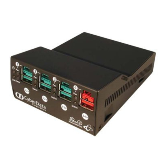
Hub Power LED Link LED Port 1 Status LED Figure 2-4. CyberData 4-Port PoweredUSB 2.0 Hub—Back View 2.2 Product Compatibility The 4-Port PoweredUSB Hub is compatible with the following operating systems and USB standards. Operating systems Windows 2000 and XP LINUX... -
Page 9: Installation
2.3 Installation The 4-Port PoweredUSB Hub is a tabletop unit with mounting feet that sit on a flat surface. 2.4 Connections This following topics provide illustrations and information on connecting the 4-Port PoweredUSB Hub to power supplies, the host, and peripheral devices. -
Page 10: Power Supply
See Port PoweredUSB Hub. CAUTION The P1 and P2 DC input jacks on the back of this Hub are for input only. Do not plug power supplies into both input jacks simultaneously as equipment damage that might void the product warranty could occur. -
Page 11: Poweredusb Connections
The lower portion of the “A” connector side on Figure 2-7. Color-Coding for Connectors Teal 12 Volt Keyed 1.5A each Ports 1,2, and 3 930103D Installing and Using the 4-Port PoweredUSB Hub 24 Volt Keyed 2.3A Ports 4 CyberData Corporation... - Page 12 Installing and Using the 4-Port PoweredUSB Hub Figure 2-8. USB PoweredUSB Socket Connector Pin Assignments CyberData Corporation PIN OUT Signal Description Vbus Ground Ground Vplus Vplus Ground Shell Shield 930103D USB standard “A” USB standard “A” USB standard “A” USB standard “A”...
-
Page 13: Peripherals Connections To The 4-Port Poweredusb Hub
2.4.5 Peripherals Connections to the 4-Port PoweredUSB Hub This figure illustrates the cable routing from the 4-Port PoweredUSB Hub to the Dell Retail Integrator. Figure 2-9. Top view of Hub PoweredUSB cable routing CyberData 4-Port PoweredUSB Hub Operations Guide Installing and Using the 4-Port PoweredUSB Hub... -
Page 14: Peripheral Cable Connection Options
Installing and Using the 4-Port PoweredUSB Hub 2.4.6 Peripheral Cable Connection Options Figures 10 through 16 provide examples of peripheral cable combinations and connection options for the 4-Port PoweredUSB Hub. The following table provides details about the CyberData PoweredUSB Cables displayed in these figures. PoweredUSB... - Page 15 Installing and Using the 4-Port PoweredUSB Hub Figure 2-11. Cables; +12V PoweredUSB to +12V Power Jack and RS-232 to RS-232 Figure 2-12. Cables; +24V PoweredUSB to 3-Pin Mini-DIN and RS-232 to RS-232 or Parallel to Parallel Operations Guide 930103D CyberData Corporation...
- Page 16 Installing and Using the 4-Port PoweredUSB Hub Figure 2-13. “Y” Cable, +24V PoweredUSB to 3-Pin Power Mini-DIN and USB “B” Connectors Figure 2-14. RS232 to USB Converter “Y” Cable +12V (PC Enumerates this device as an RS-232 COM port) Figure 2-15. Cable, +24V PoweredUSB to 1x8 PoweredUSB...
-
Page 17: Operation
The 4-Port PoweredUSB Hub is a standard USB Hub that complies with the USB 2.0 specification, and adds PoweredUSB ports. When connected to a Host, it is enumerated as a Generic USB Hub. This Hub also meets the PoweredUSB .08g specification. For more information about this specification, go to www.poweredusb.org. -
Page 18: Port Electrical Specifications
Installing and Using the 4-Port PoweredUSB Hub 2.6 Port Electrical Specifications The 4-Port PoweredUSB Hub adheres to the USB 2.0 electrical specifications as follows: Standard USB Each lower portion of the PoweredUSB port provides +5V @ 500mA. If more than 500mA are drawn... -
Page 19: Appendix A Regulatory And Safety Information
● ICES-003 ● A.4 CE Declaration of Conformity This device complies with: Directive 89/336/EEC ● EN55022 Class A 1998 ● • EN61000-3-2: 2000 • EN61000-3-3: 1995 EN55024: 1998 ● • EN61000-4-2: 1995 • EN 61000-4-3:1996 Operations Guide 930103D CyberData Corporation... - Page 20 • EN 61000-4-4: 1995 • EN 61000-4-5: 1995 • EN 61000-4-6: 1996 • EN 61000-4-8: 1993 • EN 61000-4-11: 1995 CyberData Corporation 930103D Operations Guide...
-
Page 21: Appendix B Setting Up The Hub On Windows Xp
Connect the power cord to the Hub. c. With the PC powered up, connect the host control cable from the Hub to a USB port on the PC. Doing so displays the Found new hardware dialog, indicating that the PC is searching for drivers for the Hub. - Page 22 CyberData Corporation 930103D Operations Guide...
-
Page 23: Appendix C: Troubleshooting/Technical
Phone: 831-373-2601, Extension 136 Email: RMA@CyberData.net When returning a product to CyberData, an approved CyberData RMA number must be printed on the outside of the original shipping package. No product will be accepted for return without an approved RMA number. Send the product, in its original package, to the following address:... -
Page 24: Warranty
CyberData warrants its product against defects in material or workmanship for a period of two years from the date of purchase. Should the product fail within the warranty period, CyberData will repair or replace the product free of charge. This warranty includes all parts and labor. -
Page 25: Index
7 compatibility matrix 4 components list 3 connector color keys 7 CyberData license with IBM 1 CyberData contact information, corporate, sales, tech support, service 19 DC input jacks 6 Dell printer power supply 6 EMC 15 enumeration 13, 17... - Page 26 IP address to the default 19 RMA returned materials authorization 19 short circuit protection 1 technical support, contact information 19 2.0 specification 13 over current 14 warranty 1, 20 Windows XP 13, 17 CyberData Corporation 930103D Operations Guide...
Need help?
Do you have a question about the Hub and is the answer not in the manual?
Questions and answers