CyberData 011187 Operation Manual
2-port poe gigabit switch
Hide thumbs
Also See for 011187:
- Operation manual (15 pages) ,
- Installation quick reference (2 pages) ,
- Installation quick reference (2 pages)

Related Manuals for CyberData 011187


Summary of Contents for CyberData 011187
- Page 1 The IP Endpoint Company 2-Port PoE Gigabit Switch Operations Guide Part #011187 Document Part #930591G for Firmware Version 1.0.0 CyberData Corporation 3 Justin Court Monterey, CA 93940 (831) 373-2601...
- Page 2 CyberData Corporation. This manual, and the products, software, firmware, and/or hardware described in this manual are the property of CyberData Corporation, provided under the terms of an agreement between CyberData Corporation and recipient of this manual, and their use is subject to that agreement and its terms.
- Page 3 Section 1.2, "Features". • Updates Section 1.3, "Specifications". • Updates Section 1.4, "Compliance". • Adds Chapter 2, “Installing the 2-Port PoE Gigabit Switch. • Updates Figure 4, "Typical Installation of the 2-Port PoE Gigabit Switch" Operations Guide 930591G CyberData Corporation...
- Page 4 11. Prior to installation, consult local building and electrical code requirements. CyberData Corporation 930591G Operations Guide...
- Page 5 Potential safety hazards are identified in this manual through the use of words Danger, Warning, and Caution, the specific hazard type, and pictorial alert icons. CyberData Corporation 930591G Operations Guide...
-
Page 6: Table Of Contents
Appendix A The Standard RJ-45 Introduction A.1 The Standard Cable, RJ-45 Pin Assignment .......... 9 Appendix B Mounting B.1 Dimensions and Mounting Hole Measurements ........10 B.2 Mounting Option ..................11 Appendix C Typical Installation C.1 Example ....................12 Operations Guide 930591G CyberData Corporation... -
Page 7: Chapter 1 Product Overview
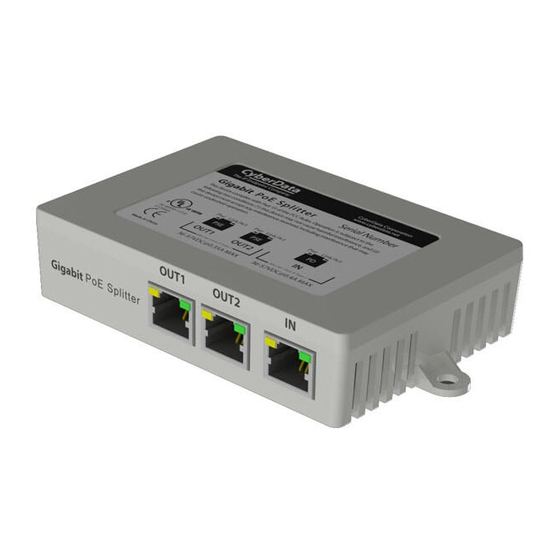
To identify the 2-Port PoE Gigabit Switch, look for a product label similar to the one shown in Figure 1-1. Confirm the following: • The part number on the label should be 011187. • The serial number on the label should begin with 187. Figure 1-1. Product Label... -
Page 8: Features
• Each port has auto MDI-X • 802.11q VLAN tagging • Automatic address learning, address aging and address migration • Supports 9216-byte jumbo frame length Notification • Link/Status and connection speed LEDs Operations Guide 930591G CyberData Corporation... -
Page 9: Specifications
– EN 62368-1; RoHS Compliant; FCC Part 15 Class A; IEEE 802.3 Compliant Part Number 011187 a. Either one or both of the PSE outputs can provide PoE power as long as the overall PSE output wattage is 2W less than the PD input. -
Page 10: Compliance
CAUTION: Changes or modifications not expressly approved by the manufacturer responsible for compliance could void the user's authority to operate the equipment. Operations Guide 930591G CyberData Corporation... -
Page 11: Chapter 2 Installing The 2-Port Poe Gigabit Switch
Leave at least 10cm of space at the front and rear of the switch to ensure adequate ventilation. 2.2.2 Desktop or Shelf Installation When installing the switch on a shelf on desktop, make sure that the previously mentioned guidelines in Section 2.2.1, "Installation Method" are followed for adequate ventilation. Operations Guide 930591G CyberData Corporation... -
Page 12: Powering On The 2-Port Poe Gigabit Switch
PD device such as IP phone is connected to the port and drawing power. PD device is not connected or no power is being drawn from the switch. Link/Act (Green) A valid link is established. Blink Traffic is present on port. No link has been established. Operations Guide 930591G CyberData Corporation... -
Page 13: Network Connection
Connect the switch from the PD port to your central Gigabit PoE Switch. • Connect your IP Phone from the PSE port on the switch. • Connect your computer or other networking device to any of the PSE2 ports on the switch. Operations Guide 930591G CyberData Corporation... -
Page 14: Appendix A The Standard Rj-45 Introduction
Figure A-1. Standard RJ-45 Jack / Connector Table A-1. RJ-45 Connector Pin Definitions Pin Number Signal _TX1 +(PoE Power+) _TX1 - (PoE Power+) _RX1 + (PoE Power-) _TX2 + _TX2 -- _RX1 - (PoE Power-) _RX2 + _RX2 - Operations Guide 930591G CyberData Corporation... -
Page 15: The Standard Cable, Rj-45 Pin Assignment
Figure A-2. Straight cable for the switch (uplink MDI-II port) to switch/Hub or other devices connection. Figure A-3. Crossover cable for switch (MDI-X port) to switch/hub or other network devices (MDI-X port) connection. Operations Guide 930591G CyberData Corporation... -
Page 16: Appendix B Mounting
Appendix B: Mounting B.1 Dimensions and Mounting Hole Measurements Figure B-1 shows the dimensions and mounting hole measurements for the 2-Port PoE Gigabit Switch. Figure B-1. Dimensions and Mounting Hole Measurements CyberData Corporation Ø0.217 www.cyberdata.net [Ø5.5] 3.033 [77.0] 4.832 [122.7] 1.063 [27.0]... -
Page 17: Mounting Option
2-Port PoE Gigabit Switch. Figure B-2. Mounting Mounting Option: 1. Mounting Screw • Use a size 6 to 8 pan head screw. 2. Adhesive • Peel off the adhesive backing and attach the unit to a suitable surface. Operations Guide 930591G CyberData Corporation... -
Page 18: Appendix C Typical Installation
Appendix C: Typical Installation C.1 Example Figure C-1 shows a typical installation setup for the 2-Port PoE Gigabit Switch. Figure C-1. Typical Installation Operations Guide 930591G CyberData Corporation...
Need help?
Do you have a question about the 011187 and is the answer not in the manual?
Questions and answers