Pilz PNOZ mc3p Operating Manual
Configurable safety systems pnozmulti
Hide thumbs
Also See for PNOZ mc3p:
- Operating manual (29 pages) ,
- Configuration manual (359 pages) ,
- Operating instructions manual (12 pages)
Table of Contents
Advertisement
Advertisement
Table of Contents

Related Manuals for Pilz PNOZ mc3p


Summary of Contents for Pilz PNOZ mc3p
- Page 1 PNOZ mc3p Configurable safety systems PNOZmulti Operating Manual-21010-EN-07...
- Page 2 Preface This document is the original document. All rights to this documentation are reserved by Pilz GmbH & Co. KG. Copies may be made for the user's internal purposes. Suggestions and comments for improving this documenta- tion will be gratefully received.
-
Page 3: Table Of Contents
PROFIBUS DP interface Preparing for operation 6.2.1 Setting the station address 6.2.2 Download modified project to the control system PNOZmulti 6.2.3 Connection example Section 7 Operation Messages Display elements 7.2.1 Display elements for device diagnostics Operating Manual PNOZ mc3p 21010-EN-07... - Page 4 Contents Section 8 Technical details Section 9 Order reference Product Accessories Operating Manual PNOZ mc3p 21010-EN-07...
-
Page 5: Introduction
Introduction Introduction Validity of documentation This documentation is valid for the product PNOZ mc3p. It is valid until new documentation is published. This operating manual explains the function and operation, describes the installation and provides guidelines on how to connect the product. - Page 6 Introduction INFORMATION This gives advice on applications and provides information on special fea- tures. Operating Manual PNOZ mc3p 21010-EN-07...
-
Page 7: Overview
24 - 127 are used they have different properties (see document en- titled "Communication Interfaces"). Max. 1 PNOZ mc3p can be connected to the base unit Please refer to the document "PNOZmulti System Expansion" for the PNOZmulti base units that can be connected. -
Page 8: Front View
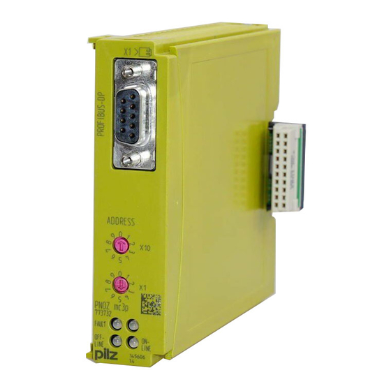
Overview Front view ADDRESS PNOZ mc3p FAULT OFF- LINE LINE Key: PROFIBUS-DP interface (female 9-pin D-Sub connector) LEDs: – FAULT – OFFLINE – ONLINE Operating Manual PNOZ mc3p 21010-EN-07... -
Page 9: Safety
PNOZmulti and PROFIBUS-DP. PROFIBUS-DP is designed for fast data exchange at field level. The expansion module PNOZ mc3p is a passive subscriber (Slave) of PROFIBUS-DP (DPV0). The basic functions of communication with PROFIBUS-DP conform to EN 50170. The central controller (Mas- ter) reads input information from the slaves and writes output information to the slaves as part of each cycle. -
Page 10: Safety Regulations
Any type of modification has been made (e.g. exchanging components on the PCB boards, soldering work etc.). 3.3.3 Disposal When decommissioning, please comply with local regulations regarding the disposal of electronic devices (e.g. Electrical and Electronic Equipment Act). Operating Manual PNOZ mc3p 21010-EN-07... -
Page 11: For Your Safety
Do not open the housing or make any unauthorised modifications. Please make sure you shut down the supply voltage when performing maintenance work (e.g. exchanging contactors). Operating Manual PNOZ mc3p 21010-EN-07... -
Page 12: Function Description
The virtual inputs and outputs that are to be transferred via PROFIBUS are selected and configured in the PNOZmulti Configurator. The base unit and the expansion module PNOZ mc3p are connected via a jumper. The expansion module PNOZ mc3p is also supplied with voltage via this jumper. -
Page 13: Block Diagram
Byte 1: Bits 0 … 7 Byte 2: Bits 0 … 7 The number of virtual inputs and outputs can be extended to 128 (see document "Commu- nication Interfaces" in the section entitled "Fieldbus modules") Block diagram Operating Manual PNOZ mc3p 21010-EN-07... -
Page 14: Installation
Damage due to electrostatic discharge! Electrostatic discharge can damage components. Ensure against discharge before touching the product, e.g. by touching an earthed, conductive sur- face or by wearing an earthed armband. Dimensions in mm 22,5 94 (3.70") (0.88") Operating Manual PNOZ mc3p 21010-EN-07... -
Page 15: Connecting The Base Unit And Expansion Modules
Installation Connecting the base unit and expansion modules You can install a maximum of 1 PNOZ mc3p to the left of the base unit. Connect the base unit and the expansion module as described in the operating instructions for the base units. -
Page 16: Commissioning Wiring
8: A (RxD/TxD-N) 9: n.c. n.c. = not connected Please note the following when connecting to PROFIBUS-DP: Only use metal plugs or metallised plastic plugs Twisted pair, screened cable must be used to connect the interfaces Operating Manual PNOZ mc3p 21010-EN-07... -
Page 17: Preparing For Operation
6.2.1 Setting the station address The station address of the expansion module PNOZ mc3p is set between 0 ... 99 (decimal) via two rotary switches x1 and x10. On the upper rotary switch x10, use a small screwdriver to set the tens digit for the ad- dress (“3”... -
Page 18: Connection Example
Commissioning 6.2.3 Connection example PROFIBUS-DP PROFIBUS-DP Slave n PROFIBUS-DP Slave 1 Slave 3 PROFIBUS-DP Master PNOZ mc3p PROFIBUS ADDRESS PNOZ mc3p PROFIBUS-DP FAULT OFF- Slave 2 LINE LINE Operating Manual PNOZ mc3p 21010-EN-07... -
Page 19: Operation
"OFFLINE" LEDs indicate the status of the PNOZ mc3p on PROFIBUS-DP. If the expansion module PNOZ mc3p does not receive a configuration from the base unit for a period of 30 s, the expansion module PNOZ mc3p connects to PROFIBUS-DP and "ONLINE"... - Page 20 Ensure that the right GSD file has been used. 2 Hz Configuration error, length/contents of configuration data during initialisation of the PNOZ mc3p does not match the configuration Remedy: Ensure that the right GSD file has been used. 4 Hz...
-
Page 21: Technical Details
Vibration In accordance with the standard EN 60068-2-6 Frequency 10,0 - 150,0 Hz Acceleration Shock stress In accordance with the standard EN 60068-2-27 Acceleration Duration 11 ms Max. operating height above sea level 2000 m Operating Manual PNOZ mc3p 21010-EN-07... - Page 22 27 mm Material Bottom PPO UL 94 V0 Front ABS UL 94 V0 Dimensions Height 94,0 mm Width 22,5 mm Depth 119,0 mm Weight 119 g Where standards are undated, the 2011-09 latest editions shall apply. Operating Manual PNOZ mc3p 21010-EN-07...
-
Page 23: Order Reference
Order reference Order reference Product Product type Features Order No. PNOZ mc3p Fieldbus module, PROFIBUS-DP 773 732 Accessories Jumper Product type Features Order No. KOP-XE Jumper 774 639 Operating Manual PNOZ mc3p 21010-EN-07... - Page 24 Front cover Support Technical support is available from Pilz round the clock. Americas Australia Scandinavia Brazil +61 3 95600621 +45 74436332 +55 11 97569-2804 Spain Canada Europe +34 938497433 +1 888-315-PILZ (315-7459) Austria Switzerland Mexico +43 1 7986263-0 +41 62 88979-30...
Need help?
Do you have a question about the PNOZ mc3p and is the answer not in the manual?
Questions and answers