Pilz PNOZ m1p Operating Manual
Configurable safety systems pnozmulti
Hide thumbs
Also See for PNOZ m1p:
- Operating instructions manual (16 pages) ,
- Configuration manual (359 pages) ,
- Operating instructions manual (12 pages)

Related Manuals for Pilz PNOZ m1p


Summary of Contents for Pilz PNOZ m1p
- Page 1 PNOZ m1p (ETH) Configurable safety systems PNOZmulti Operating Manual-20878-EN-16...
- Page 2 Preface This document is the original document. All rights to this documentation are reserved by Pilz GmbH & Co. KG. Copies may be made for the user's internal purposes. Suggestions and comments for improving this documenta- tion will be gratefully received.
-
Page 3: Table Of Contents
Requirements of the connection cable and connector 6.2.3 Interface configuration 6.2.4 RJ45 connection cable 6.2.5 Process data exchange Function test during commissioning Commissioning the PNOZmulti control system for the first time 6.4.1 Load project from chip card Operating Manual PNOZ m1p (ETH) 20878-EN-16... - Page 4 Function test of the relay outputs Reset Ethernet connection settings Section 8 Technical Details Safety characteristic data Section 9 Supplementary data Service life graph for the relay contacts Section 10 Order reference 10.1 Product 10.2 Accessories Operating Manual PNOZ m1p (ETH) 20878-EN-16...
-
Page 5: Operating Manual Pnoz M1P (Eth)
Introduction Introduction Validity of documentation This documentation is valid for the product PNOZ m1p. It is valid until new documentation is published. This operating manual explains the function and operation, describes the installation and provides guidelines on how to connect the product. - Page 6 Introduction INFORMATION This gives advice on applications and provides information on special fea- tures. Operating Manual PNOZ m1p (ETH) 20878-EN-16...
-
Page 7: Overview
Base unit PNOZ m1p Terminator Documentation on data medium Unit features Application of the product PNOZ m1p: Base unit from the configurable control system PNOZmulti The product has the following features: Can be configured in the PNOZmulti Configurator Positive-guided relay outputs: –... -
Page 8: Chip Card
(please refer to the document "PNOZmulti System Expansion" for details of the type and number that can be connected) Integrated interfaces: – PNOZ m1p: Serial interface RS232 – PNOZ m1p ETH: 2 Ethernet interfaces Plug-in connection terminals: Either spring-loaded terminal or screw terminal available as an accessory (see order... -
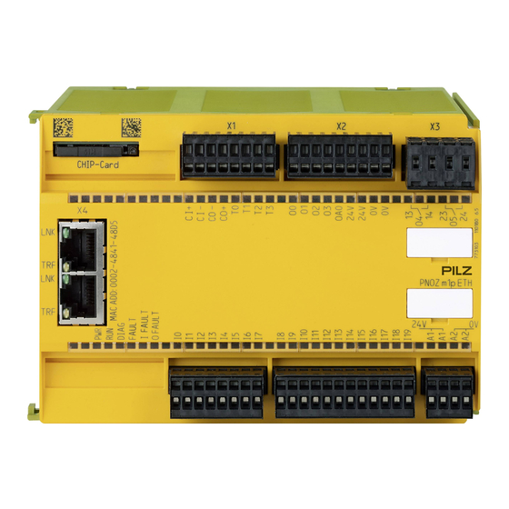
Page 9: Front View
Overview Front view PNOZ m1p CHIP-Card Operating Manual PNOZ m1p (ETH) 20878-EN-16... - Page 10 Semiconductor outputs O0 ... O3, Auxiliary output OA0, Supply connections Relay outputs O4 and O5 RS232 interface / Ethernet interface X5, X6 Inputs I0 ... I19 Power supply LEDs: DIAG FAULT I FAULT O FAULT Operating Manual PNOZ m1p (ETH) 20878-EN-16...
-
Page 11: Safety
Safety circuits in accordance with VDE 0113 Part 1 and EN 60204-1 CAUTION! Inputs and outputs for standard functions must not be used for safety-re- lated applications. The coated version of the product PNOZ m1p is suitable for use where there are increased environmental requirements (see Technical details [ 30]). -
Page 12: Use Of Qualified Personnel
Adequate protection must be provided for all inductive consumers. Do not open the housing or make any unauthorised modifications. Please make sure you shut down the supply voltage when performing maintenance work (e.g. exchanging contactors). Operating Manual PNOZ m1p (ETH) 20878-EN-16... -
Page 13: Function Description
Block diagram A1 A2 I4 I5 I9 I10 Input O4 O5 Power Test pulse Cascading output 24 V CI+ CI- CO+ CO- T0 T1 T2 T3 O0 O1 O2 O3 24 V 14 24 Operating Manual PNOZ m1p (ETH) 20878-EN-16... -
Page 14: Diagnostics
PNOZmulti Configurator and in the docu- ment entitled "PNOZmulti - Special Applications". Interfaces The product PNOZ m1p ETH has two Ethernet interfaces, the product PNOZ m1p has one serial interface to Project download... -
Page 15: Installation
NOTICE Damage due to electrostatic discharge! Electrostatic discharge can damage components. Ensure against discharge before touching the product, e.g. by touching an earthed, conductive sur- face or by wearing an earthed armband. Operating Manual PNOZ m1p (ETH) 20878-EN-16... -
Page 16: Dimensions
Install base unit without expansion module The terminator must be fitted to the side of the base unit marked “Termination/Link”. Do not fit a terminator on the left hand side of the base unit. Termination/Link Terminator Operating Manual PNOZ m1p (ETH) 20878-EN-16... -
Page 17: Connecting The Base Unit And Expansion Modules
A terminator must not be fitted to the last expansion module to the left of the base unit. Fieldbus module Expansion module 1 ... 8 Expansion module 1 ... 4 Power supply Base unit Terminator Jumpers Operating Manual PNOZ m1p (ETH) 20878-EN-16... -
Page 18: Commissioning
Do not route the test pulse lines together with actuator cables within an unprotected multicore cable. Test pulse outputs are also used to supply safety mats that trigger a short circuit. Test pulses that are used for the safety mat may not be reused for other purposes. Operating Manual PNOZ m1p (ETH) 20878-EN-16... -
Page 19: Ethernet Interfaces (Eth Version Only)
Shielded RJ45 connectors (industrial connectors) 6.2.3 Interface configuration RJ45 socket 8-pin Standard Crossover TD+ (Transmit+) RD+ (Receive+) TD- (Transmit-) RD- (Receive-) RD+ (Receive+) TD+ (Transmit+) n.c. n.c. n.c. n.c. RD- (Receive-) TD- (Transmit-) n.c. n.c. n.c. n.c. Operating Manual PNOZ m1p (ETH) 20878-EN-16... -
Page 20: Rj45 Connection Cable
Appropriate design measures should be used to ensure that the plug-in connection is insensitive to in- creased mechanical stress (e.g. through shock, vibration). Such measures include fixed routing with strain relief, for example. Operating Manual PNOZ m1p (ETH) 20878-EN-16... -
Page 21: Process Data Exchange
The RJ45 interfaces on the internal autosensing switch enable process data to be ex- changed with other Ethernet subscribers within a network. The product PNOZ m1p can also be connected to Ethernet via a hub (hub or switch). Ethernet Hub/Switch... -
Page 22: Commissioning The Pnozmulti Control System For The First Time
Connect the computer containing the PNOZmulti Configurator to the base unit via the interface. Switch on the supply voltage. Download the project (see PNOZmulti Configurator's online help). INFORMATION You will need a PC with an Ethernet card in order to establish an Ethernet connection. Operating Manual PNOZ m1p (ETH) 20878-EN-16... -
Page 23: Download Modified Project To The Pnozmulti System
For the safety system + 24 V DC (connector X7) For the semiconductor outputs + 24 V DC 24 V (connector X2) Must always be present, even if the semiconductor outputs are not used Supply voltage Operating Manual PNOZ m1p (ETH) 20878-EN-16... - Page 24 Input circuit with detection of shorts across contacts shorts across contacts Connection examples for start circuit Redundant output O0 (O2) O1 (O3) Single output O0 (O2) O1 ( O3) Connection examples for semiconductor outputs Operating Manual PNOZ m1p (ETH) 20878-EN-16...
- Page 25 Commissioning Redundant output Single output Connection examples for relay outputs Feedback loop Redundant output Contacts from external contactors O0 (O2, O4) O1 (O3, O5) Connection examples for feedback loop Operating Manual PNOZ m1p (ETH) 20878-EN-16...
-
Page 26: Connection Example
Commissioning Connection example Dual-channel E-STOP and safety gate wiring, monitored start (I17), feedback loop (I14), cascading output as auxiliary output (CO+/A2) Operating Manual PNOZ m1p (ETH) 20878-EN-16... -
Page 27: Operation
External error on the base unit inputs, which does not lead to a safe condition, e.g. partially operated External error on the base unit outputs, which does not lead to a safe condition, e.g. feedback input defective Operating Manual PNOZ m1p (ETH) 20878-EN-16... -
Page 28: Indicators For The Ethernet Connection (Eth Version Only)
Start the device again or open the safety contacts (switch off output), so that the internal diagnostics can check the correct opening of the safety contacts for SIL CL 3/PL e at least 1x per month for SIL CL 2/PL d at least 1x per year Operating Manual PNOZ m1p (ETH) 20878-EN-16... -
Page 29: Reset Ethernet Connection Settings
You can reset the base unit's Ethernet connection settings to the default settings. Proceed as follows: Switch off the supply voltage Remove the chip card Restart the base unit without the chip card inserted. The Ethernet connection settings are now reset to the default settings. Operating Manual PNOZ m1p (ETH) 20878-EN-16... -
Page 30: Technical Details
15 - 30 V DC 15 - 30 V DC 15 - 30 V DC Input voltage in ac- cordance with EN 61131-2 Type 1 24 V DC 24 V DC 24 V DC 24 V DC Operating Manual PNOZ m1p (ETH) 20878-EN-16... - Page 31 UB - 0.5 VDC at 0.5 UB - 0.5 VDC at 0.5 UB - 0.5 VDC at 0.5 Signal level at "1" Test pulse outputs 773100 773103 773104 773105 Number of test pulse outputs Operating Manual PNOZ m1p (ETH) 20878-EN-16...
- Page 32 72 W 72 W 72 W 72 W Airgap creepage between Relay contacts 3 mm 3 mm 3 mm 3 mm Relay contacts and other circuits 5,5 mm 5,5 mm 5,5 mm 5,5 mm Operating Manual PNOZ m1p (ETH) 20878-EN-16...
- Page 33 0,5 s 0,5 s 0,5 s 0,5 s Max. cycle time of the device 15 ms 15 ms 15 ms 15 ms Max. processing time for data com- munication – 50 ms 50 ms – Operating Manual PNOZ m1p (ETH) 20878-EN-16...
- Page 34 EN 60068-2-27 EN 60068-2-27 EN 60068-2-27 EN 60068-2-27 Acceleration Duration 11 ms 11 ms 11 ms 11 ms Max. operating height above sea level 2000 m 2000 m 2000 m 2000 m Operating Manual PNOZ m1p (ETH) 20878-EN-16...
- Page 35 ABS UL 94 V0 ABS UL 94 V0 Connection type Spring-loaded ter- Spring-loaded ter- Spring-loaded ter- Spring-loaded ter- minal, screw ter- minal, screw ter- minal, screw ter- minal, screw ter- minal minal minal minal Operating Manual PNOZ m1p (ETH) 20878-EN-16...
- Page 36 0,25 - 0,75 mm², 24 0,25 - 0,75 mm², 24 0,25 - 0,75 mm², 24 0,25 - 0,75 mm², 24 nector - 20 AWG - 20 AWG - 20 AWG - 20 AWG Operating Manual PNOZ m1p (ETH) 20878-EN-16...
- Page 37 135,0 mm 135,0 mm 135,0 mm Depth 121,0 mm 121,0 mm 121,0 mm 121,0 mm Weight 499 g 518 g 538 g 519 g Where standards are undated, the 2010-10 latest editions shall apply. Operating Manual PNOZ m1p (ETH) 20878-EN-16...
-
Page 38: Safety Characteristic Data
A safety function's SIL/PL values are not identical to the SIL/PL values of the units that are used and may be different. We recommend that you use the PAScal software tool to calculate the safety function's SIL/PL values. Operating Manual PNOZ m1p (ETH) 20878-EN-16... - Page 39 If the service life graphs are not accessible, the stated PFH value can be used irrespective of the switching frequency and the load, as the PFH value already considers the relay's B10d value as well as the failure rates of the other components. Operating Manual PNOZ m1p (ETH) 20878-EN-16...
-
Page 40: Supplementary Data
The service life graphs indicate the number of cycles from which failures due to wear must be expected. The wear is mainly caused by the electrical load; the mechanical load is negli- gible. Switching current (A) Fig.: Service life graphs at 24 VDC and 230 VAC Operating Manual PNOZ m1p (ETH) 20878-EN-16... - Page 41 To increase the service life, sufficient spark suppression must be provided on all relay con- tacts. With capacitive loads, any power surges that occur must be noted. With DC contact- ors, use flywheel diodes for spark suppression. We recommend you use semiconductor outputs to switch 24 VDC loads. Operating Manual PNOZ m1p (ETH) 20878-EN-16...
-
Page 42: Order Reference
793 100 Terminator, jumper Product type Features Order No. PNOZmulti bus terminator Terminator 779 110 PNOZmulti bus terminator Terminator, coated version 779 112 coated KOP-XE Jumper 774 639 KOP-XE coated Jumper, coated version 774 640 Operating Manual PNOZ m1p (ETH) 20878-EN-16... - Page 43 Front cover Support Technical support is available from Pilz round the clock. Americas Australia Scandinavia Brazil +61 3 95600621 +45 74436332 +55 11 97569-2804 Spain Canada Europe +34 938497433 +1 888-315-PILZ (315-7459) Austria Switzerland Mexico +43 1 7986263-0 +41 62 88979-30...
Need help?
Do you have a question about the PNOZ m1p and is the answer not in the manual?
Questions and answers