Table of Contents
Advertisement
Advertisement
Table of Contents

Related Manuals for Xtool PS80


Summary of Contents for Xtool PS80
- Page 1 PS80 Diagnosis System User Manual...
- Page 2 PS80 Diagnosis System Declaration 1. This manual is designed for the usage of PS80, applying to PS80 automotive diagnosis platform. No part of this manual can be reproduced, stored in a retrieval system or transmitted, in any form or by any means (electronic, mechanical, photocopying, recording, or otherwise), without the prior written permission of Xtool.
- Page 3 PS80 Diagnosis System Xtool PS80 Diagnosis System Main Unit Maintenance Avoid shaking or dismantling the unit as it may damage the internal components. Do not use hard or sharp objects to touch the LCD screen; do not use excessive force;...
-
Page 4: Table Of Contents
3. PS80 Technical Parameters..................2 CHAPTER Ⅱ How to Use PS80 ..................3 1. PS80 Activation ......................3 2. PS80 Main Interface and Functional Buttons Descriptions ........4 2.1. Main Interface ......................4 2.2. Sub-menu and Functional Buttons ............... 5 2.3. -
Page 5: Chapter Ⅰ About Ps80
PS80 Diagnosis System CHAPTER Ⅰ About PS80 1. Appearance 1.1. Front View 1.2. Back View... -
Page 6: Layout Of Ps80 Tablet
PS80 Diagnosis System 2. Layout of PS80 Tablet 2.1. Top View of PS80 Tablet ① ② ③ ④ ① Charging port: Battery charging ② DB15 Port: Supports wired connection with car by the cable ③ USB Type C Port: Compatible with HDMI TV port, and support for quick charging ④... -
Page 7: Chapter Ⅱ How To Use Ps80
240×177×30mm CHAPTER Ⅱ How to Use the PS80 1. PS80 Activation 1.1. Please activate PS80 before you use it to test vehicles. And please connect WiFi first. 1.2. Input activation code (on the Quality Certificate cover), product serial number (each device will have a serial number and activation code), nickname (workshop’s name or user’s nickname), login account (can be your email address or cell phone... -
Page 8: Ps80 Main Interface And Functional Buttons Descriptions
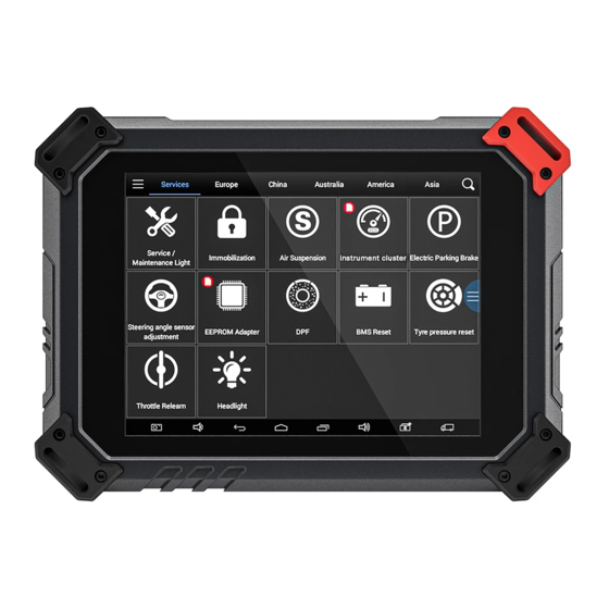
PS80 Diagnosis System 2. PS80 Main Interface and Functional Buttons Descriptions 2.1. Main Interface Tap on PS80 application icon, the main interface and sub-menus will be shown as below.▼... -
Page 9: Sub-Menu And Functional Buttons
Online Communication Platform for PS80 users. (English version is coming soon) Click UPDATE after PS80 is connected to internet, then you can download the latest diagnostic software directly to PS80. Users can view all the diagnostic reports and diagnostic data generated in the diagnosis process. -
Page 10: Vehicle Connection Diagnosis
3.1. Vehicle Connection Test a. Turn on PS80 tablet b. Connect cables and PS80 in following order: ①→②→③→④ c. Switch on the ignition and tap on PS80 application to test vehicles. (Shown as follows) ① PS80 Mainframe ② Main Test Cable ③... -
Page 11: Diagnosis
PS80 unit. 4.Diagnosis 4.1. Menu Options 4.1.1. After the scanner is connected to the vehicle and paired with PS80 mainframe via wired or wireless connection, diagnosis can be performed. The diagnostic interface is as shown below: 4.1.2. Users can choose the relevant menu for the vehicle being tested: selection for Europe will enter the European cars menu, selection for Asia will enter the Asian cars menu, selection for America will enter the American cars menu. -
Page 12: Test Functions
PS80 Diagnosis System 4.2. Test Functions 4.2.1. Using VW as an example, select Diagnosis, then select EUROPE. Choose the VW word. If the word is not showing on the screen, please swipe up or down to display it. PLEASE NOTE: Different vehicles have different menus and systems. - Page 13 Users can then enter the nature of the problem and any other relevant information and send the form to the Xtool engineering department.
-
Page 14: Read Ecu
PS80 Diagnosis System 4.3. Read ECU This function is used to read ECU version information, which is the equivalent of “System Identification” or “System Information” in some electronic control systems. This will allow you to read ECU related software and hardware versions, models and production date of diesel engine, part number, etc. -
Page 15: Clear Dtcs
PS80 Diagnosis System Tip: In the process of diagnosis, if the device shows “System is OK” or “No Trouble Code”, it indicates that the ECU has not detected a fault in any of the circuits that it monitors. If there is a fault which is not being recorded it may be that the fault is with a part of the system not under the control of ECU, such as a mechanical system fault. -
Page 16: Read Live Data
PS80 Diagnosis System 4.5.2. Click YES to confirm the operation, if the communication is normal, it will show “Trouble Codes Successfully Cleared” or “Trouble Codes Cleared”. Generally, users will need to re-read trouble codes after clearing them to confirm that the trouble codes have been cleared. - Page 17 PS80 Diagnosis System Tip: Live Data is important function that can be used to help technicians further diagnose a problem. This function requires technicians to be familiar with sensor data of each system, control signals and control modes. Tip: Save known good live data readings for comparison.
- Page 18 PS80 Diagnosis System...
-
Page 19: Special Functions
PS80 Diagnosis System 4.7. Special Functions Different vehicle makes and models will have different special functions. 4.8. Actuation/Active Components Test Test Conditions: Ignition on engine off. If the engine is started or an engine rotation speed signal is received, component actuation will be interrupted. -
Page 20: Settings
PS80 Diagnosis System Actuating components can be checked by hearing or touching. 4.8.1. Return to Dynamic Diagnostic Data, enter Test Actuator and it will show the menu of the components that are available to actuate, shown below: Tip: Actuating Components Test performs function tests for system components. When performing this function, the diagnostic tool will simulate the ECU signal to enable the user to judge whether the actuating components or circuits are working correctly. -
Page 21: Xcloud
7. Update PS80 updates directly via the Internet using WiFi or wired connection. To access the update application open the PS80 application and click UPDATE , shown below:... -
Page 22: Report
PS80 Diagnosis System 8. Report Report is used for viewing and printing the saved files, such as Live Data, Trouble Codes or pictures generated in the process of diagnosis, users also can view a record of which cars have been previously tested. It includes three parts: PDF Files, Pictures and Data Playback. - Page 23 PS80 Diagnosis System 8.1.2 Click PDF icon to generate PDF when you want to save the trouble code report 8.2. Data Replay: With Data Playback you can play back recorded Live Data & freeze frame data.
-
Page 24: Remote
If users encounter problems and are not able to solve them, they can open this application and ask for remote assistance. How to get remote assistance from Xtool Technical Assistance Center: a. Open PS80 b. Click Remote and open the TeamViewer interface. Generate and display device ID. -
Page 25: Diagnostic Link Connectors Locations Of Various Vehicle Models
PS80 Diagnosis System CHAPTER Ⅲ Examples of Diagnostic Link Connector Locations. 1. Diagnostic Link Connectors Locations of Various Vehicle Models *AUDI A6: the OBD plug is on the lower left side of the dashboard, use SMART OBDII-16 connector. - Page 26 PS80 Diagnosis System *VW Bollywood 1.8: the OBD plug is below the console, use SMART OBDII-16 connector. *Benz S320,220 Chassis: the OBD plug is below the dashboard, use SMART OBDII-16 connector. *Benz C180: the OBD plug is on the left hand side of the engine bay, use Benz-38...
- Page 27 PS80 Diagnosis System *Benz 300SEL 140 chassis: the OBD plug is on the left hand side of the engine bay, use Benz-38 connector. *GM Buick: the OBD plug is below the dashboard, use SMART OBDII-16 connector. *GM Buick GL8 : the OBD plug is below the dashboard, use SMART OBDII-16...
- Page 28 PS80 Diagnosis System *VW POLO: the OBD plug is below the dashboard, use SMART OBDII-16 connector. *BMW 735I: the OBD plug is in the right hands side of the engine bay, use BMW-20 connector. *VW Passat B5: the OBD plug is behind the gearlever and beside the parking brake...
-
Page 29: Location Diagram Of Vehicle Diagnostic Link Connectors
PS80 Diagnosis System 2. Location Diagram of Vehicle Diagnostic Link Connectors Location diagram of pick-up truck diagnostic link connectors: Location diagram of utility vehicles diagnostic link connectors: Link diagram of small car diagnostic link connectors: NOTE: Each vehicle manufacturer may use additional pins to diagnose a variety of systems. - Page 30 PS80 Diagnosis System Pin Definition (Reference material) Various pin definitions as follows: 1. Manufacturer definition 2. SAE J1850 bus positive 3. Manufacturer definition 4. Bodywork site 5. Signal site 6. ISO 15765-4 defined CAN high 7. ISO9141 and ISO14230 defined K line 8.
- Page 31 FCC Statement This device complies with part 15 of the FCC rules. Operation is subject to the following two conditions: (1) this device may not cause harmful interference, and (2) this device must accept any interference received, including interference that may cause undesired operation. Changes or modifications not expressly approved by the party responsible for compliance could void the user's authority to operate the equipment.
Need help?
Do you have a question about the PS80 and is the answer not in the manual?
Questions and answers