Table of Contents
Advertisement
Advertisement
Table of Contents

Related Manuals for Husqvarna Rider 100 series


Summary of Contents for Husqvarna Rider 100 series
- Page 1 Workshop manual Rider 100-series English 1 – English...
-
Page 2: Table Of Contents
Workshop Manual Rider 100-series Contents Safety Instructions ..........3 Wheels ............16 General directions ........... 3 Administration ..........16 Special directions ..........3 Design and Function ........17 Special Tools ............4 General ............17 Technical Data 111 B5/111 B ....... 5 Serial number .......... -
Page 3: Safety Instructions
Safety Instructions General directions Special directions This workshop manual is written for personnel with The fuel used in the Rider has the following a general knowledge of repairing and servicing hazardous properties: Rides. • T he fluid and its vapor are toxic. The workshop where the Rider is to be repaired •... -
Page 4: Special Tools
Special Tools The following special tools are used when working on the Rider. Special tools for engine and transmission can be found in the respective workshop manual. 535 41 32- 02 535 41 32-02 535 41 32-02 Mandrel for assembling the bushings on the swing axle. 4 –... -
Page 5: Technical Data 111 B5/111 B
Technical Data Rider 111B5 Rider 111B Dimensions Length without cutting unit, mm/ft 1734/5.69 1734/5.69 Length with cutting unit, mm/ft 2100/6.89 2100/6.89 Width without cutting unit, mm/ft 785/2.56 785/2.56 Width with cutting unit, mm/ft 883/2.90 883/2.90 Height, mm/ft 1084/3.56 1084/3.56 Service weight with cutting unit, kg/lb 165/364 165/364 Wheelbase, mm/ft... -
Page 6: Transmission
Specifications Transmission Rider 111B5 Rider 111B Make Peerless MST 205 Hydrogear T2 Oil, grade SF-CC SAE 80W/90 SAE 20W/50 Number of forward gears Number of reverse gears Forward speed, km/h Reverse speed, km/h Cutting unit Type BioClip unit BioClip unit Cutting heights, 5 positions, mm/inch 25-70 / 1-2 3/4 25-70 / 1-2 3/4... -
Page 7: Technical Data 112 C5/112 C
Technical Data Rider 112C5 Rider 112C Dimensions Length without cutting unit, mm/ft 1781/5.84 1781/5.84 Length with cutting unit, mm/ft 2100/6.89 2100/6.89 Width without cutting unit, mm/ft 797/2.61 793/2.60 Width with cutting unit, mm/ft 883/2.90 883/2.90 Height, mm/ft 1084/3.56 1084/3.56 Service weight with cutting unit, kg/lb 191/421 191/421 Wheelbase, mm/ft... -
Page 8: Transmission
Transmission Rider 112C5 Rider 112C Make Peerless MST 205 Tuff Torq T36P Oil, grade SF-CC SAE 80W/90 SAE 20W/50 Number of forward gears Number of reverse gears Forward speed, km/h Reverse speed, km/h Cutting unit Type Combi unit Combi unit Cutting heights, 5 positions, mm/inch 25-70 / 1-2 3/4 25-70 / 1-2 3/4 Blade length, mm/inch... -
Page 9: Technical Data 115 C5/120 C
Technical Data Rider 115C Rider 120C Dimensions Length with cutting unit, mm/ft 2290/7.52 2290/7.52 Width with cutting unit, mm/ft 990/3.25 1260/4.13 Height, mm/ft 1080/3.56 1080/3.56 Service weight with cutting unit, kg/lb 219/482.5 221/487.2 Wheelbase, mm/ft 845/2.77 845/2.77 Tire dimension 165/60-8 165/60-8 Air pressure rear - front, kPa (bar/PSI) 60 (0.6/8.7) -
Page 10: Cutting Unit
Cutting unit Type Combi unit Combi unit Cutting heights, 5 positions, mm/inch 25-75/1-3 25-75/1-3 Blade length, mm/inch 430/17 430/17 Note. 1: The power rating of the engine is the average net output (at the specified rpm) of a typical production engine of the model, measured to SAE standard J1349/ISO1585. Mass production engines may differ from this value. Actual power output for the engine installed in the final machine will depend on the operating speed, environmental conditions and other variables. Note. 2: Emission of noise to the surroundings measured as sound power (LWA) in accordance with the EU directive 2000/14/EC. -
Page 11: Delivery And Dealer Service
Delivery and Dealer Service Dealer Service 8-hour service 300-hour service 1. Change the engine oil. 1. Inspect the machine. Reach agreement with the customer about which additional work should 25-hour service be carried out. 1. Change engine oil on top valve engine at high 2. -
Page 12: Service Schedule
Delivery and Dealer Service Service Schedule The following is a list of maintenance procedures that must be performed on the Rider. For those points not described in this workshop manual, refer to the operator’s manual. Page Daily mainte- nance before starting Check the engine oil level Check the engine cooling air intake Check the fuel pump’s air filter Check the steering wires Check the brakes... -
Page 13: Delivery Measures
Delivery Measures Packaging and unpacking To our dealers On delivery from the factory, the Rider is normally A well-performed delivery service is the first step packed in special packing. This comprises a bottom to a functioning aftermarket. It is in everybody's interest to have a functioning aftermarket: board of wood with a top of sturdy cardboard, kept together with plastic film. -
Page 14: Battery
Delivery measures Battery Connecting the jump leads WARNING! IMPORTANT INFORMATION Measures after contact with acid Your Rider is equipped with a 12-volt system with negative ground. The other External: Rinse with plenty of water. vehicle must also have a 12-volt system with negative ground. -
Page 15: Steering Wheel
Delivery measures Steering Wheel Checking the engine’s oil level. Check the engine oil level when the Rider is standing on a flat surface with the engine turned off. Raise the engine cover. Loosen the dipstick, pull it up and wipe it off. 1 Fit the steering wheel with steering column tube onto the steering column. Ensure the holes are The dipstick should be completely screwed down. -
Page 16: Wheels
Delivery measures Wheels The tire pressure should be 60 kPa (0.6 bar / 8.5 PSI) on all wheels. IMPORTANT INFORMATION Different pressures in the front wheels will make the blades cut the grass at different heights. Administration Complete the sales certificate, customer register, etc. Do not forget to enter the serial number into the operator's manual and certify the delivery service in the service book. -
Page 17: Design And Function
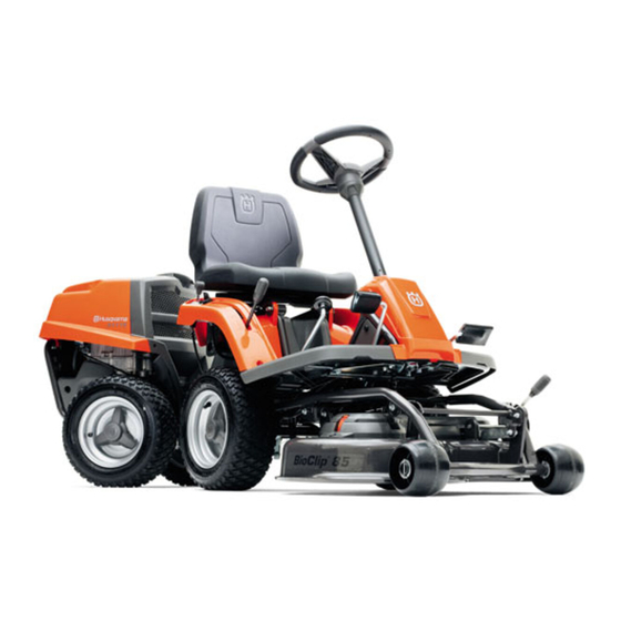
They all also have front-mounted cutting units for controlled mowing and the best possible cutting results. Husqvarna Riders are also equipped with accessories such as lawn rake and snow blade, making them flexible tools for all-year-round use. Riders 111B5 and 112C5 are delivered with manual transmission, other Rider models are delivered only with hydrostatic transmission. -
Page 18: Serial Number
Design and Function Serial number The machine's serial number can be found on the R112, R115, R120 printed plate (1) attached to the right below the engine cover. Stated on the plate, from the left, are: • The machine’s type designation (Model). • The manufacturer’s type number (PNC). • The machine's serial number (Serial Number) Please provide the type designation and serial number when ordering spare parts. -
Page 19: Engine
Design and Function Engine The Husqvarna Rider 100 series has a one- cylinder, air cooled engine from Briggs & Stratton. For information concerning the motors fitted to respective Rider models, see the Specification chapter. Major engine repairs are not described in the workshop manual. Detailed information on adjustment and reparation of the engine is available in Briggs &... -
Page 20: Steering
Design and Function Steering All Riders in the Rider range have articulated steering. The force from the steering wheel is transferred to the rear carriage via cables and a chain. This makes the Rider easy and precise to steer. A Rider mows easily around all the obstacles on the lawn. -
Page 21: Drive
Without the BioClip- confined spaces. plug the unit works in the same way as a rear ejection unit. The Rider 100 series has a cutting width of 850 mm (34") or 950 mm (38”), Combi. BioClip/Combi. Removing the BioClip plug... -
Page 22: Repair Instructions
Repair Instructions Dismount the engine The figures show a Rider 112C. 1 First disconnect the negative terminal on the battery and then the positive terminal. IMPORTANT INFORMATION! Hold the bolts so that the poles are not put under strain. 4 Remove the covers on the back of the machine, the side covers and the cover over the fuel tank. - Page 23 5 Place a suitable vessel underneath the fuel tank to collect the gasoline in. 6 Remove the clamp and hose from the fuel tank 8 Disconnect the engine pin connector, the ground and drain the fuel into the vessel. There are two cable and the starter motor cable.
- Page 24 11 Unscrew the muffler. 14 Unscrew the remaining 3 screws from the engine block. 12 Unhook the spring on the drive belt pulley in the articulated unit and turn the belt tensioner to one side. 15 Lift off the engine. Assemble in reversed order. 13 Loosen the drive belt from the pulley under the engine plate.
-
Page 25: Fuel Tank
Fuel tank Removal WARNING! Gasoline is highly flammable and environmentally hazardous. Take great care to prevent fires and avoid spills. 1 Place a suitable vessel underneath the fuel filter to collect the gasoline in. Rider 112/112C5, 115C/120C 3 Remove the two screws (1) holding the tank. Lower the tank and pull out the hose through the machine frame. -
Page 26: Changing Engine Oil
Changing engine oil Checking and adjusting the steering cables For information about oil change intervals; see the "Service Schedule". The steering is controlled with cables. These can stretch after a time, which means the steering WARNING! settings can change. Engine oil can be very hot if it is Steering can be checked and adjusted in the drained directly after stopping the following way:... -
Page 27: Replacing Steering Cables
Replacing the Steering Cables 4 Ensure that the steering wheel is in the center position when the rear wheels are centered. Re- 1 Loosen the rear fastening of the steering set the chain on the steering column's sprocket cables (1). or adjust the rear fixture (1) for the steering cables as needed. -
Page 28: Removing/Fitting Steering Shaft
Removing/Fitting the Steering Shaft 4 Unscrew the screw (2) in the lower edge of the steering wheel rod. 1 Loosen the rear fastening of the steering 5 Pull the steering wheel shaft (3) upwards and cables (1). move the lower part of the shaft backwards to pull off the steering chain (4). -
Page 29: Removing/Fitting Cable Pulley
Repair instructions Removing/assembling the cable pulley Ensure that the cables are properly placed in the steering cable pulleys (7). 1 Loosen the rear fastening of the steering Ensure that the steering wheel is in the center cables (1). position when the rear wheels are centered. Re- 2 Remove the screw (2) and the cable pulley (5). -
Page 30: Checking And Adjusting Brake Cable
Repair instructions Checking and adjusting the brake cable Rider 111 B5/112 C5 Rider 111B The brake is properly adjusted when the brake lever (1) is completely vertical. If it is not, adjust the brake wire by pulling the rubber sleeve (2) aside, Ensure that the brake is properly adjusted by loosening the lock nut (3), adjusting the nut (4) so measuring the gap between the brake lever (3) and... -
Page 31: Checking And Adjusting Gear Control
Repair instructions Checking and adjusting the gear control Checking and adjusting the clutch Rider 111 B5/112 C5 Rider 111 B5 Check the gear control adjustment by putting the gear lever in the "N" position. If the machine moves easily, the lever is properly adjusted. Otherwise the controls should be adjusted as follows: Rider 112/ /112 C5/ 115 C/ 120 C... -
Page 32: Checking And Adjusting Accelerator
Repair instructions lever arm. Fit the socket on the ball. 6 Lock the adjustment with the lock nut (1) and put the locking spring (2) in place. Changing articulated steering bearing Rider 111 B5 3 Adjust the clutch cable as follows: •... - Page 33 Repair instructions 6 Pull belt 1 off the belt pulley. Rider 111 B5/112 C5: 3 Remove the rear cover of the front carriage. 7 Loosen the spring that is tensioning belt 2 4 Loosen the spring for belt 1 (engine belt) using a (transmission belt) using a spring hook. spring hook.
- Page 34 Repair instructions 10 Remove the rear attachments of both steering cables. 8 Pull off belt 2 from the transmission, first from the rear belt pulley and then from the front. 11 Loosen the articulated shaft's screw from below. Rider 111 B5/112 C5 9 Loosen belt 3 (cutting unit drive) from the tension roller. Then pull it off from the center belt pulley, then from the belt pulley of the articulated steering.
- Page 35 Repair instructions 14 Jack up the front carriage in front of the cable pulley without squeezing any cables. Jack up 13 Loosen the two screws (4) using a half-inch the rear carriage in the rear edge. wrench. Loosen the screw (5) behind the muffler and the screw (6) holding the exhaust pipe. The belt guide can now be removed.
-
Page 36: Removing The Pivoting Rear Axle
Repair instructions Removing the pivoting rear axle 1 Follow step 1 to 15 in "Replacing the Articulated Steering Bearings". 2 Remove the front wheels to obtain better access. 3 Remove all the cables laid out between the front and the rear carriage, in their rear attachments. Make a note of how the cables are laid out. -
Page 37: Replacing Pendulum Shaft Bushings
Repair instructions Replacing the pendulum shaft bushings Replacing the bearings in the articulation unit belt pulleys Once the swing axle has been remove, the bushings in the rear frame must be changed. Remove the cover (1) on the right hand side. Loosen the spring (2) with a spring hook. -
Page 38: Assembling Pivoting Rear Axle
Repair instructions Assembling the pivoting rear axle 5 Fit the articulated shaft with the short key grip and plastic cover face down. Ensure the double D shaft is inserted into the double D hole on the 1 Slide the washer (2) on the pendulum shaft with fork. -
Page 39: Replacing Hydrostatic Cable
Repair instructions Replacing the hydrostatic cable Rider 111 B/112 C/115 C/120 C Removing the hydrostatic cable 3 Remove the front hydrostatic cable clamp that is fastened inside the center console. 1 Remove the frame cover and the front cover. 4 Cut off the plastic tie around the cable at the frame situated in front of the left front wheel. - Page 40 Repair instructions Fitting the hydrostatic cable 1 Feed the new cable through the Rider so it runs 6 Lift the link joint off and remove the hydrostatic the same route as the old one. cable. Loosen the rear link joint from the cable. Turn the cable so that it comes loose from the front link joint.
- Page 41 Repair instructions 4 Tighten the hydrostatic transmission cable 7 Place the hydrostatic transmission cable in place clamp. and screw the casing on with the rear bracket (3). 8 Adjust the hydrostatic transmission cable as shown, see Checking and Adjusting the Accelerator.
-
Page 42: Replacing Brake Cable
Repair instructions Replacing brake cable Removing the brake cable Fitting the brake cable 1 Pull through the new brake cable on the Rider. 1 Unhook the spring in the front part of the brake cable. 2 Fit the rear of the cable. 3 Fit the front part of the cable by hooking on the 2 Loosen the rear part and remove the brake spring. -
Page 43: Replacing Belt 4, As Far As Cutting Unit
Repair instructions Replacing belt 4, as far as the cutting unit Starting position for removing belts: • No unit is attached to the machine. • The front part of the belt is loose. • The lifting lever is lowered. 1 Jack up the front carriage and remove the left front wheel. -
Page 44: Replacing Belt 3, Cutting Unit Drive
Repair instructions Replacing belt 3, cutting unit drive Follow the instructions for "Replacing belt 4, as far as the cutting unit" up until step 7. Then proceed according to the following instructions: 7 Pull belt 3 off the unit belt pulley. 1 Remove the rear cover of the front frame. 8 Lift off belt 4 over the unit belt pulley and forwards. - Page 45 Repair instructions 4 Lift off belt 1. 6 Remove the cover on the left hand side of the rear carriage. 5 Remove the spring for the belt tensioner for belt 2 (transmission belt). Rider 111 B5: Rider 111 B/112 /115 C/120 C: 7 Pull off belt 2 from the transmission, first from the rear belt pulley and then from the front.
-
Page 46: Removing The Cutting Unit
Repair instructions Removing the cutting unit The cutting unit can be removed in order to facilitate cleaning and servicing. To remove the cutting unit proceed as follows: 1 Put the machine in a level position. 5 Loosen the snap-in lock and lift off front cover. 2 Apply and secure the parking brake. 6 Unhook the spring. -
Page 47: Service Position For Cutting Unit
Repair instructions Service position for cutting unit Follow the instructions for "Removing the cutting unit" above. Lift off the unit and lean it against the machine or a wall. 4 Push the unit until you feel the pipes touch bottom. Attaching the cutting unit 5 Fit the belt according to the picture. 1 Place the belt under the stay of the cutting unit. -
Page 48: Removal Of Blades And Blade Housing
Repair instructions Removal of blades and blade housing WARNING! Use gloves and protective goggles when working on the cutting unit. The cutting unit should be removed from the machine, see "Removing the cutting unit". 4 Secure the blade with a wooden block or hold the belt pulley with an oil filter puller for example. -
Page 49: Grinding And Balancing Blades
Repair instructions 7 The whole bearing package is available as a complete kit with shaft housing, shaft and bearings. Assembly is done in reverse order to dismantling. 3 Balance the blades as follows: The blade bolt tightening torque is 45-50 Nm •... -
Page 50: Electrical System
Electrical System Wiring diagram 1. Microswitch, seat 6. Starter relay 2. Ignition switch 7. Grounding point engine 3. Microswitch, lifting lever 8. Starter motor 4. Microswitch, pedal 9. Solenoid valve carburettor 5. Fuse, 15A 10. Battery 50 – English... -
Page 51: Electrical System Components
Electrical System Electrical system components Microswitch cutting unit The electrical system consists of four cables, three microswitches, one ignition switch and one fuse. If the Rider does not start (the start engine does not rotate when the key switch is turned to the starting position), one of the electrical system components might be damaged. -
Page 52: Ignition And Starter Switch
Electrical System Ignition and starter switch Main fuse The main fuse is placed in a detachable holder 1 Unplug the connector from the ignition switch by behind the battery under the protective cover. pulling straight down. 2 Remove the ignition key and the rubber seal. 3 Remove the nut and the ignition switch. - Page 53 115 73 80-26 2018W44...
Need help?
Do you have a question about the Rider 100 series and is the answer not in the manual?
Questions and answers
How to remove rider 155 brake cable that seems to be stuck in the front frame bracket,