Table of Contents
Advertisement
Quick Links
Advertisement
Table of Contents

Related Manuals for Husqvarna Rider 13 AWD


Summary of Contents for Husqvarna Rider 13 AWD
- Page 1 Workshop manual Rider 13 AWD Rider 155 AWD Rider 15V2 AWD English...
-
Page 2: Table Of Contents
Workshop Manual for the Rider 13 AWD, Rider 155 AWD and Rider 15V2 AWD Contents..............1 Changing the Engine Oil, Kohler....... 58 Safety Instructions..........3 Checking the Engine’s Oil Level, Kawasaki ..59 General Instructions ..........3 Fuel Tank ............60 Special Instructions ..........3 Changing the Engine Oil, Kawasaki.... - Page 3 Ignition and Starter Lock .........119 Main Fuses ............119 Safety System ..........120 Microswitch: Lifting lever........121 Microswitch: Seat..........121 Microswitch: Pedal arrangement......121 Hydraulic System ..........122 Hydraulic Hygiene ...........122 Hydraulic Oils ..........122 Fixing Oil Leaks ..........122 Keep the Hydraulic Oil Clean ......123 Working Methods ..........123 Hydraulic System AWD........124 Hose Bundle ...........125 Appendix: Trouble Shooting Guide...
-
Page 4: Safety Instructions
SAFETY INSTRUCTIONS Safety Instructions General Instructions No one may repair the rider unless they have read This workshop manual is written for personnel with and understood the content of this workshop general knowledge about the repair and service of manual. riders. -
Page 5: Risk Of Sparking
SAFETY INSTRUCTIONS Risk of sparking Sparking can occur when working with the battery and the thick cables in the starter motor circuit. This can cause the battery to explode, fire or eye injuries. Sparking in the circuit can not occur once the battery’s power connection cable (usually the black negative cable) has been disconnected. -
Page 6: Special Tools
SPECIAL TOOLS Special Tools The following special tools are used when working on the rider. Special tools for the engine and transmission are specified in resp. Workshop Manuals. 506 66 48-01 506 56 76-01 506 89 92-01 506 89 93-01 535 41 32-01 506 79 06-01 6021-034... - Page 7 SPECIAL TOOLS 506 66 48-01 506 56 76-01 506 79 06-01 8009-518 6021-035 8009-517 8009-515 The figures show how the special tools are used. English-...
-
Page 8: Laser Tachometer
SPECIAL TOOLS Laser tachometer Safety • Laser product class 1. • Exercise care when the laser beam is on. • Do not look straight at the beam. Do not aim the beam towards anyone else’s eyes, either people or animals. •... -
Page 9: Specifications
SPECIFICATIONS Specifications Rider 13 AWD Rider 15 V2 AWD Rider 155 AWD Dimensions and weight Length, base machine 2010 mm / 6.58 ft 2020 mm / 6.61 ft 2020 mm / 6.61 ft Length with Combi 112 2400 mm / 7.87 ft 2450 mm / 8.04 ft... - Page 10 SPECIFICATIONS Rider 13 AWD Rider 15 V2 AWD Rider 155 AWD Electrical System Type 12 V, negative grounded 12 V, negative grounded 12 V, negative grounded Battery 12 V, 24 Ah 12 V, 24 Ah 12 V, 24 Ah Main fuse...
- Page 11 SPECIFICATIONS Cutting unit Combi 94 Combi 103 Cutting width 940 mm / 37" 1030 mm / 40.5" Cutting heights 45–95 mm / 1.75–3.75" 45–95 mm / 1.75–3.75" Blade length 360 mm / 14" 410 mm / 16" Guaranteed noise level 100 dB(A) 100 dB(A) Width...
-
Page 12: Delivery And Dealer Service
DELIVERY AND DEALER SERVICE Delivery and Dealer Service Delivery Service After the first 5 resp. 8 hours Fill the battery with battery acid and charge for Briggs & Stratton and Kohler after 5 hours and four hours. Kawasaki after 8 hours. Fit the steering wheel, seat and, where Change engine oil. -
Page 13: 300-Hour Service
DELIVERY AND DEALER SERVICE 300-Hour Service At Least Once Each Season Inspect the machine. Come to agreement with Clean the engine’s cooling air intake (25 hours). the customer as to what additional work is to Replace the air cleaner’s pre-filter (foamed be carried out. -
Page 14: Service Schedule
DELIVERY AND DEALER SERVICE Service Schedule = Described in this workshop manual. The following is a list of maintenance procedures that must be performed on the rider. Most of the ❍ = Not described in this workshop manual or the points that are not described in this workshop operator’s manual. - Page 15 DELIVERY AND DEALER SERVICE Maintenance Page Daily Daily At least Maintenance interval in Weekly mainte- mainte- once a hours mainte- nance nance year nance before after Clean around all belts, belt – pulleys, etc. Lubricate the belt adjuster – (nipple) Lubricate all cables –...
- Page 16 DELIVERY AND DEALER SERVICE Maintenance Page Daily Daily At least Maintenance interval in Weekly mainte- mainte- once a hours mainte- nance nance year nance before after ❍ ❍ Check the play in the engine valves Check whether the oil needs to be 4, 5) changed in the transmission (every 200 hours).
-
Page 17: Delivery Procedures
DELIVERY AND DEALER SERVICE Delivery Procedures To our dealers In conjunction with the delivery, you shall also give A well performed pre delivery service is the first the customer the information required to handle step towards an active after-sales market. and maintain their machine in a safe manner. - Page 18 DELIVERY AND DEALER SERVICE Packaging and Unpacking Packed components: The machine is normally packed using special Number Component packaging when delivered from the factory. This 1 pc Steering wheel with steering rod packaging is comprised of a wood base with a strong cardboard top section, all held together with 1 pc Allen screw for steering rod...
-
Page 19: Battery
DELIVERY AND DEALER SERVICE Battery WARNING! Actions with acid contact External: Rinse thoroughly with water. Internal: Drink large quantities of water or milk. Contact a doctor as soon as possible. Eyes: Rinse thoroughly with water. Contact a doctor as soon as possible. -
Page 20: Steering Wheel
DELIVERY AND DEALER SERVICE Steering Wheel • Fit the steering wheel with the steering rod on the steering column. Choose a suitable height position. • Thread the Allen screw into the thread of the steering column. Work the wheel and tighten the Allen screw so that it reaches the bottom of the thread. -
Page 21: Check The Oil Level In The Hydraulic Tank
DELIVERY AND DEALER SERVICE Check the oil level in the hydraulic tank Remove the transmission cover. Loosen both screws (one on each side) and lift off the transmission cover. Leave the cover removed for now. 6021-030 Transmission cover Check that there is oil in the hydraulic tank. Fill if necessary with engine oil SAE 10W/40 (class SF-CC). -
Page 22: Checking And Adjusting The Cutting Unit
DELIVERY AND DEALER SERVICE Checking and Adjusting the Cutting Unit Performed after checking the tyre air pres- sures. See “Adjusting the Unit’s Parallelism and Cutting Height” on page 109. Test Running Fill with petrol. The engine should be run on a minimum of 87-octane unleaded petrol (not mixed with oil). -
Page 23: Engine Speed Regulator
Cutting height setting Engine Speed Regulator Check that the engine’s max. speed is adjusted at: Max speed Idling Rider 13 AWD 2900–3100 rpm 1500 rpm Rider 15V2 AWD 2825–2975 rpm 1500 rpm Rider 155 AWD 2825–2975 rpm 1500 rpm Inspecting the muffler Check that the muffler is fitted securely. -
Page 24: Final Inspection
DELIVERY AND DEALER SERVICE Final inspection Bleed the hydraulic system of excess air after test running. Check the oil level in the hydraulic tank and top up if necessary. Check that there are no leaks, including engine oil and fuel leaks. Replace the transmission cover. -
Page 25: Design And Function
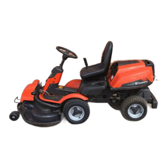
6021-001 ProFlex 21 AWD This publication describes the Husqvarna Rider In addition, the Husqvarna Riders can also be 13 AWD, Rider 15V2 AWD and Rider 155 AWD equipped with various accessories, such as moss from the 2006 model. There are special workshop rakes and snow blades, which makes them flexible... - Page 26 DESIGN AND FUNCTION Rider 13 AWD is equipped as standard with cutting unit type Combi 94 Rider 15V2 AWD and 155 AWD can be delivered with Combi 103 or Combi 112. 8009-288 6021-025 Combi 103 Combi 94 8009-288 Combi 112...
-
Page 27: Serial Number
DESIGN AND FUNCTION Serial Number The machine’s serial number is found on the printed plate at the front under the seat. Stated on the plate, from the top, are: • The machine’s type designation. • The manufacturer’s type number. • The machine’s serial number (s/n). -
Page 28: Engine
8009-206 The transmission’s serial number Engine Husqvarna Rider AWD are Rider lawn mowers with air-cooled engines from Briggs & Stratton, Kohler or Kawasaki. Major engine repairs are not described in this workshop manual. This information can be found in the engine manufacturer’s manuals,... - Page 29 DESIGN AND FUNCTION The engines can be equipped with a catalytic exhaust emission control that reduces hydrocarbons and nitrogen oxides by up to 50 % and carbon monoxide by 25 %. Machines with exhaust emission control are recognised by the green muffler guard. 8009-818 Kohler English-...
-
Page 30: Steering
DESIGN AND FUNCTION Steering A Rider easily cuts around all obstacles on the lawn. All mowers in the Rider series have articulated A mechanical linkage gives the front wheels a steering. The steering force from the steering higher speed when cornering. wheel is transmitted to the rear carriage via a chain and cables. - Page 31 8009-626 Front axle Rear axle on Rider 13 AWD, 15V2 AWD, 155 AWD from above. There is a hydraulic bypass valve that is operated by a control behind the left-hand wheel to move the machine without the rear axle’s drive engaged.
-
Page 32: Drive
DESIGN AND FUNCTION The oil is drained using two plugs on the underside. One plug drains the hydraulic motor and the other drains the differential. 8009-832 Oil drainage 8009-856 Drive system AWD English-... -
Page 33: Cutting Unit
The Combi unit functions as a BioClip unit when a BioClip plug is fitted, but can be changed to rear Rider 13 AWD is supplied with cutting unit Combi 94. ejection by removing the BioClip plug. 6021-025... - Page 34 DESIGN AND FUNCTION The mowing deck is raised and lowered using the When lowering the unit, the two connecting rods, mechanical lifting lever, which actuates a shaft that via the three-point link, will alter the belt adjuster rotates. so that the drive belt is tensioned and the blades begin to rotate.
-
Page 35: Repair Instructions
REPAIR INSTRUCTIONS Removing the Briggs & Stratton engine Remove the engine cover and transmission cover. IMPORTANT INFORMATION Hold the bolts so that the poles are not put under strain. Loosen the battery’s retaining strap. Remove the protective cover and loosen 8009-427 the cable connections. - Page 36 REPAIR INSTRUCTIONS Remove the hose clamp on the fuel hose by the fuel pump and pull the fuel hose downwards. Tie the hose higher than the fuel tank level. 8009-425 Loosen the exhaust pipe clamp. Then remove the exhaust pipe. Loosen the muffler’s mounting bolts if necessary.
- Page 37 REPAIR INSTRUCTIONS 10. Insert tool, part number 506 79 06–01, in the centre of the engine belt pulley. Loosen and remove the Allen screw that holds the belt pulley and engine shaft together. Use tool, part number 506 89 92–01, to counterhold.
- Page 38 REPAIR INSTRUCTIONS Fitting the Briggs & Stratton engine IMPORTANT INFORMATION Hold the bolts so that the poles are not put under strain. 6019-039 Lower the engine into place and tighten the engine fixtures (two on each side of the engine) with a torque of (20–25 Nm/ 14–18 lbft).
- Page 39 REPAIR INSTRUCTIONS Press in the belt adjuster and align the pump belt in position. 8009-839 Fit the belt guide. Adjust the belt guide against the lower belt in the belt pulley as needed. Fit the skid guard if used. 8009-737 Attach the throttle cable to the carburet- tor and fit the cable clip without tighten- ing it.
- Page 40 REPAIR INSTRUCTIONS Choke not actuated. 8009-404 Fit the exhaust pipe and tighten the mounting bolts on the exhaust flange and muffler and finally the pipe clamp. 8009-418 Firmly fit the fuel hose to the fuel pump and attach the hose clamp. 8009-425 10.
- Page 41 REPAIR INSTRUCTIONS 11. Screw into place the cable from the start relay to the starter. 8009-426 12. Lift the battery into position and attach the cable connectors and cover, tighten the fastening strap. 8009-427 English-...
-
Page 42: Removing And Refitting The Engine, Kohler
REPAIR INSTRUCTIONS Removing the Kohler engine Remove the engine cover. Loosen the battery’s retaining strap. Remove the protective cover. IMPORTANT INFORMATION Hold the battery cable bolts in place so that the electrodes are not strained. 8009-526 Loosen the battery cable connections. Then lift out the battery. - Page 43 REPAIR INSTRUCTIONS Remove the hose clamp on the fuel hose by the fuel pump and pull the fuel hose forwards. Place the hose so that the fuel does not leak out. 8009-809 Loosen the cover plate over the muffler, two screws on each side of the muffler, and remove the plate.
- Page 44 REPAIR INSTRUCTIONS 12. Push in the belt adjuster and pry off the pump belt. 8009-839 13. Remove the belt guide for the engine belt pulley. On machines with a skid guard the skid guard must be removed. 8009-736 14. Insert tool, part number 506 79 06–01, in the centre of the engine belt pulley.
- Page 45 REPAIR INSTRUCTIONS 16. Remove the engine fixtures, two on each side of the engine, and remove the engine from the rider. 8009-812 English-...
- Page 46 REPAIR INSTRUCTIONS Fitting the Kohler engine IMPORTANT INFORMATION When fitting the engine, it is important that the belt pulley’s groove (1) is in such a position that the outgoing shaft’s key (2) fits into the groove (see illustration). Also check that both the spacing tube (3) and key (2) are well fitted to the engine shaft.
- Page 47 REPAIR INSTRUCTIONS Fit the belt guide. Adjust the belt guide against the lower belt in the belt pulley as needed. Fit the skid guard if used. 8009-736 Connect the exhaust pipe to the cylinder. Use a new gasket. Tighten the nuts when the muffler is fitted.
- Page 48 REPAIR INSTRUCTIONS Press the fuel hose into place against the fuel pump and attach the hose clamp. 8009-809 10. Screw the cable from the starter to the start relay into place. 8009-806 11. Attach the engine’s electrical connectors. IMPORTANT INFORMATION Hold the battery cable bolts in place so that the electrodes are not strained.
- Page 49 REPAIR INSTRUCTIONS 13. Fit the transmission cover and the engine cover. 6021-030 English-...
- Page 50 REPAIR INSTRUCTIONS Removing the Kawasaki engine Remove the engine cover and transmission cover. Loosen the battery’s retaining strap. Remove the protective cover. IMPORTANT INFORMATION Hold the battery cable bolts in place so that the electrodes are not strained. 8009-526 Loosen the battery cable connections. Battery installation Then lift out the battery.
- Page 51 REPAIR INSTRUCTIONS Loosen the cover plate over the muffler, two screws on each side of the muffler, and remove the plate. 8009-035 Muffler cover plate Loosen the exhaust pipe’s pipe clamp and the muffler’s four fastening screws. Now remove the muffler and the exhaust pipe.
- Page 52 REPAIR INSTRUCTIONS 12. Push tool no. 506 56 76–01 into the cen- tre of the engine belt pulley. Loosen and remove the Allen screw that holds the belt pulley and engine shaft together. Use tool no. 506 89 92–01 to counter. Loosen the belt pulley from the engine shaft.
- Page 53 REPAIR INSTRUCTIONS Fitting the Kawasaki engine IMPORTANT INFORMATION When fitting the engine, it is important that the belt pulley’s groove (1) is in such a position that the outgoing shaft’s key (2) fits into the groove (see illustration). Also check that both the spacing tube (3) and key (2) are well fitted to the engine shaft.
- Page 54 REPAIR INSTRUCTIONS Fit the belt guide. Adjust the belt guide against the lower belt in the belt pulley as needed. Fit the skid guard. 8009-737 Belt guide Attach the throttle cable to the throttle and fit the cable clip without tightening it. Make sure that it goes into the proper hole.
- Page 55 REPAIR INSTRUCTIONS Press the fuel hose into place against the fuel pump and attach the hose clamp. 8009-191 Fuel pump Screw the cable from the starter to the start relay into place. Attach the engine’s electrical connectors. 8009-190 The engine’s electrical connections IMPORTANT INFORMATION Hold the battery cable bolts in place so that the electrodes are not strained.
-
Page 56: Checking The Engine's Oil Level, Briggs & Stratton
REPAIR INSTRUCTIONS Checking the engine’s oil level, Briggs & Stratton Check the oil level in the engine when the Rider stands horizontal with the engine switched off. Open the engine cover. Loosen the dipstick and pull it out. Wipe off the dipstick and fit it again. -
Page 57: Changing The Engine Oil, Briggs & Stratton
REPAIR INSTRUCTIONS Changing the engine oil, Briggs & Stratton The engine oil should be changed the first time after 5 hours running time. It should then be changed after every 50 hours of running time. With heavy loads or high temperatures replace the oil after every 25 hours of driving. -
Page 58: Checking The Engine's Oil Level, Kohler
REPAIR INSTRUCTIONS Checking the engine’s oil level, Kohler Check the oil level in the engine when the Rider stands horizontal with the engine switched off. Open the engine cover. Loosen the dipstick and pull it out. Wipe off the dipstick and fit it again. The dipstick should not be screwed into place. -
Page 59: Changing The Engine Oil, Kohler
REPAIR INSTRUCTIONS Changing the engine oil, Kohler The engine oil should be changed the first time after 5 hours running time. It should then be changed after every 100 hours of running time. With heavy loads or high temperatures replace the oil after every 50 hours of driving. WARNING! Engine oil can be very hot if it is drained directly after stopping the... -
Page 60: Checking The Engine's Oil Level, Kawasaki
REPAIR INSTRUCTIONS Checking the engine’s oil level, Kawasaki Check the oil level in the engine when the Rider stands horizontal with the engine switched off. Open the engine cover. Loosen the dipstick, pull it up and wipe it off. Now insert the dipstick again, without tightening it. -
Page 61: Fuel Tank
REPAIR INSTRUCTIONS Fuel tank Removal WARNING! Petrol is highly flammable and environmentally hazardous. Exercise caution to avoid fire and spillage. Place an appropriate container to catch the petrol. The tank holds approx. 7 litres / 7.4 USqt. Empty the petrol tank by removing the hose from the connector under the tank. -
Page 62: Changing The Engine Oil Kawasaki
REPAIR INSTRUCTIONS Changing the engine oil Kawasaki The engine oil should be changed the first time after 8 hours running time. It should then be changed after every 100 hours of running time. WARNING! Engine oil can be very hot if it is drained directly after stopping the engine. -
Page 63: Checking And Adjusting The Steering Cables
REPAIR INSTRUCTIONS Checking and Adjusting the Steering Cables The steering is governed by means of cables. After a period of use these can become stretched, which means the steering setting may have changed. Steering is checked and adjusted as follows: Remove the frame plate by loosening the screws. -
Page 64: Replacing The Steering Cables
REPAIR INSTRUCTIONS 8009-372 Power steering and steering cables Replacing the Steering Cables Loosen the steering cables’ rear mount (1). Remove the frame plate. Loosen the steering cables’ front fixture (2) by the steering chain (3) and pull out the steering cables through the frame. -
Page 65: Removing/Fitting The Cable Pulleys
REPAIR INSTRUCTIONS 8009-371 Steering cables and cable pulley Removing/Fitting the Cable Pulley Remove the frame plate and skid guard under the machine. Loosen the steering cables’ rear mount (1). Remove the screw (2) and remove the cable pulley (5). Remove the bearing’s circlip (3) and tap out the bearing (4). -
Page 66: Adjusting The Parking Brake, Rider Awd-Machines
REPAIR INSTRUCTIONS Adjusting the parking brake, Rider AWD-machines Check that the parking brake is adjusted correctly by placing the machine on a slope with the front and rear axles disengaged. Apply and lock the parking brake. When the machine does not stand still, the parking brake should be adjusted according to the following. -
Page 67: Adjusting The Hydrostatic Transmission Cable
REPAIR INSTRUCTIONS Adjusting of the Hydrostatic Transmission Cable The hydrostatic transmission cable is adjusted as follows: Remove the transmission cover. Loosen both screws (one on each side) and lift off the transmission cover. Check that the front ball joint on the rod is fitted in the second hole from the top on the rear axle’s control arm. -
Page 68: Checking And Adjusting Of Throttle And Choke Cables, Kohler
REPAIR INSTRUCTIONS Checking and adjusting of throttle and choke cables, Kohler Loosen the cable clamp so the casing moves. Move the accelerator to the full throttle position without choke. 8009-808 Pull the outer cover on the cable until there is no play between the arm for the choke control and the adjuster screw at the rear of the stop plate and tighten the cable clamp. -
Page 69: Adjusting The Throttle Cable, Briggs & Stratton
REPAIR INSTRUCTIONS Adjusting the throttle cable, Briggs & Stratton The throttle cable may need to be adjusted, if the engine does not respond as it should when accelerating, if it produces black smoke or maximum revs are not reached. Loosen the clamping screw (by the arrow), and slide the throttle to the choke position. -
Page 70: Checking And Adjusting The Choke Cable, Kawasaki
REPAIR INSTRUCTIONS Checking and adjusting the choke cable, Kawasaki If the engine produces black smoke or is difficult to start, this can be because the choke cable is incorrectly adjusted (upper cable). If adjustments are necessary, they can be made as follows: Loosen the clamping screw for the cable’s outer casing and move the choke lever to the full choke position. - Page 71 REPAIR INSTRUCTIONS Remove the locking spring and loosen the throttle control’s link joint locking spring, and remove the cable’s bracket from the rear frame and the ball joint. 8009-203 Clean, see “Working Methods” on Locking spring page 123. Mark and remove the hydraulic hoses from the couplings under the machine.
- Page 72 REPAIR INSTRUCTIONS 11. Remove the inner circlip (1) by the lower bearing (see illustration). The rear carriage is now loose and can be moved. Then loosen the outer circlip (2) and remove the bearings from below. 6012-027 Lower bearings 12. Remove the upper bearings from above; if they are stuck tap them from below.
-
Page 73: Removing The Pendulum Shaft
REPAIR INSTRUCTIONS Removing the Pendulum Shaft Jack up the rider in front of the rear frame. Clean, see “Working Methods” on page 123. 6012-029 Jacking up Mark and remove the hydraulic hoses from the couplings under the machine. 8009-820 Hydraulic hoses Loosen the idler’s spring. -
Page 74: Replacing Bushings
REPAIR INSTRUCTIONS Remove the hydrostatic transmission cable from the arm and the casing from the bracket. 8009-822 Hydrostatic cable Remove the circlip and lift off the hydrostatic transmission’s fan. Remove the rear belt from the impeller and the adjuster pulley. Remove the circlip and washer from the 8009-823 pendulum shaft and pull loose the rear... -
Page 75: Fitting The Pendulum Shaft
REPAIR INSTRUCTIONS Fitting the Pendulum Shaft Lubricate half the shaft (the half that has not been lathed) and press it into the steering spindle from the rear (see illustration). Fit the washer and circlip on the pendulum shaft by the inner mount. Fit the dust cover (with thin lip towards the rear) approx. - Page 76 REPAIR INSTRUCTIONS • Remove the circlip. • Pull off the wheel with hub from the axle. • Take care of the keys, spacers and washers, keep a check of the number of washers, this can vary between sides. 8009-825 Circlip Release the front synchronisation link for speed from the front axle.
- Page 77 REPAIR INSTRUCTIONS Release the hydraulic pipe from the top of the front axle. Fit the protective plugs. A small amount of oil will leak out even if the front axle has not been drained. 8009-826 Hydraulic pipe, top Remove the five bolts holding the front axle and lower the front axle.
- Page 78 REPAIR INSTRUCTIONS 8009-829 Rear front axle mounting 10. Release the parking brake cable from the front axle. 8009-691 Parking Brake Cable 11. Loosen the stop screws (2) and remove the bearing on right-hand side. 8009-625 Right front axle bearings Assembly Assemble the front axle in the reverse order in relation to dismantling.
-
Page 79: Rear Axle
REPAIR INSTRUCTIONS Pipe couplings are lightly oiled before assembly. Grease the axles for protection against corrosion before the wheels are fitted. The spacer sleeves on the inside of the wheels are of different lengths. Left 36.3 mm with washer Right 45.5 mm, no washer Do not mix up the rear axle’s spacer sleeves. - Page 80 REPAIR INSTRUCTIONS Drain out the oil if necessary, two plugs. 8009-832 Oil drainage Mark the hydraulic hoses and release from the underside of the rear axle. Fit the protective plugs. A small amount of oil will leak out even if the axle has not been drained.
- Page 81 REPAIR INSTRUCTIONS Release the cable and link rod for the accelerator from the horizontal arm. Remove the clutch control. Pry off the rear V-belt from the fan pulley. Place the belt over the groove on the crankshaft belt pulley and move it between the fan blades.
- Page 82 The measurement can be made without special tools, but is much easier when Husqvarna’s laser tachometer is used. Max. deviation is 5 %. Check that the synchronisation link is fitted in the top hole on the front axle’s arm.
- Page 83 REPAIR INSTRUCTIONS Jack up and block the machine with the wheels on one side on the ground and the wheels on the other side in the air. Check that the steering wheel position has not changed. Mark the free rolling wheels at the same angle with tape, chalk line or the like.
-
Page 84: Replacing The Hydrostatic Transmission Shaft Seals
REPAIR INSTRUCTIONS Replacing the Hydrostatic Transmission Shaft Seals Seal Replacement, Ingoing Shaft Remove the cooling fan, it is held by a circlip. Remove the belt pulley from the ingoing shaft by pulling it upwards and then removing the circlip under the pulley. IMPORTANT INFORMATION The area around the seal must be abso- lutely clean! If the hydrostatic transmis-... - Page 85 REPAIR INSTRUCTIONS Place the seal on the shaft with the smooth side up and press it carefully down. Use the thick end of a 1/4" extender to carefully tap the seal down until the top of the seal is even with the upper edge of the shaft housing.
- Page 86 REPAIR INSTRUCTIONS Wrap insulating tape around the out- going shaft from the beginning of the key groove and outwards until even the threads of the circlip are covered with tape. This is done to protect the new seal from damage. Lubricate the shaft and the inside of the new seal with lubricant so that the seal slips on smoothly.
-
Page 87: Replacing The Hydrostatic Transmission Cable
REPAIR INSTRUCTIONS 11. Bleed the hydraulic system of excess air, according to “Bleeding the drive system” on page 91. 12. Run the rider and make sure that there are no oil leaks from the new shaft seals. 13. Check the oil level after test running and top up as needed. - Page 88 REPAIR INSTRUCTIONS Remove the transmission cover. 6021-030 Transmission cover Remove the spring lock and the hydro- static transmission cable’s rear link joint from the arm. Remove the rear clamp. 8009-214 Rear link joint Lift off the front link joint and pull out the cable.
-
Page 89: Fitting The Hydrostatic Transmission Cable
REPAIR INSTRUCTIONS Remove the entire hydrostatic transmis- sion cable. 6019-009 Remove the hydrostatic transmission cable. Fitting the Hydrostatic Transmission Cable Screw in the front link joint on the new hydrostatic transmission cable and tighten the lock nut. 6019-018 Front link joint Run the cable through the rider so that it follows the same path as the old cable did. - Page 90 REPAIR INSTRUCTIONS Press in the cable casing in the forward fastener in the centre bracket. 6019-023 Forward mount in centre bracket Tighten the hydrostatic transmission cable’s front clamp. Press the link joint onto its fastener and attach the locking spring. 6019-024 Front clamp Attach the link joint to the rear part of the...
- Page 91 REPAIR INSTRUCTIONS 10. Connect the rear link joint and attach the locking spring. 8009-203 Locking spring 11. Tighten the rear link joint’s lock nut. 12. Screw on the frame plate. 13. Test drive the machine forwards and in reverse. 6019-021 Frame plate English-...
-
Page 92: Bleeding The Drive System
REPAIR INSTRUCTIONS Bleeding the drive system IMPORTANT INFORMATION Ensure cleanliness. Used oil may not be reused. Handle waste oil as environmental hazardous waste. Avoid skin contact; wash with soap and water in case of spillage. See “Hydraulic Hygiene” on page 122. IMPORTANT INFORMATION The tank must never be run empty while work is underway. - Page 93 REPAIR INSTRUCTIONS Fill the tank completely with oil. Wait a few minutes and top up. 6012-048 Transmission oil tank Turn the wheels by hand and top up. Make sure that the clutch control valves are closed. Start the engine and idle, top up. Release the parking brake and actuate the forward and reverse pedals 4 x 5 seconds, top up.
-
Page 94: Adjustment Of The Transmission's Neutral Position
REPAIR INSTRUCTIONS Adjustment of the transmission’s neutral position Bleed the drive system, see “Bleeding the drive system”. Lift the rear of the Rider, front and back, so that the all wheels spin freely and place jack stands under the machine. The neutral position is adjusted by turning the hexagonal shaft on the transmission (see figure). -
Page 95: Transmission Maintenance
REPAIR INSTRUCTIONS Method 2 1 = Shaft 2 = Lock nut If the drive shafts do not rotate backwards despite the fact that the hexagonal shaft has rotated a full revolution, the neutral position is to be adjusted in the following manner: •... - Page 96 REPAIR INSTRUCTIONS Hydrostatic transmission front axle / rear axle The transmission holds about 5 litres (5.2 US qt) (SAE 10W/40 engine oil, class SF–CC or higher). Drain the hydrostatic transmissions using the two plugs on each axle. Replace the hydrostatic transmission filter, see separate instructions.
-
Page 97: Adjusting The Lever Housing
REPAIR INSTRUCTIONS Remove the cover and pull out the filter. 6020-003 Hydrostatic transmission filter Fit the new filter in position. Coax it in so that the rubber seal in the front end-plate enters its position. If the spring protrudes so that it must be pressed together before the cover “threads catch”... -
Page 98: Replacing The Hydraulic Pump's Drive Belt
REPAIR INSTRUCTIONS Replacing the hydraulic pump’s drive belt Removal Remove the transmission cover. 6021-030 Transmission cover Pry off the belt from the belt adjuster. 8009-839 Belt tensioning Remove the belt guide for the centre belt. 8009-736 Belt guide Pull off the centre belt from the engine’s pulley and pull out the rear section. - Page 99 REPAIR INSTRUCTIONS Pry off the pump belt upwards on the engine pulley. Pry off the pump belt from the pump pulley. Guide the belt between the fan blades. Pull the pump belt off of the engine’s pulley and move it under the engine belt pulleys.
-
Page 100: Replacing The Centre Belt
REPAIR INSTRUCTIONS Replacing the Centre Belt Remove the rear belt guide for the centre belt. Remove the centre belt and mount a 8009-737 Rear belt guide new belt. Fit and adjust the belt guide with the lower belt on the engine belt pulley. 8009-736 Belt guide Check and adjust the belt adjuster. -
Page 101: Replacing The Front Belt
REPAIR INSTRUCTIONS Replacing the front belt Dismantling The entire belt is removed according to the following when a snow blade is to be attached to the machine. Put the cutting unit in the service position. Pull the centre belt off of the centre pulley. - Page 102 REPAIR INSTRUCTIONS Place the centre belt in position in the centre pulley’s lower groove. 8009-695 Centre pulley Reset the cutting unit in the mowing position. Make sure that the tongue (3) mates with the loop on the underside of the machine. 8009-595 Tongue in the loop The belt is fitted on the cutting unit’s...
-
Page 103: Equipment Frame
REPAIR INSTRUCTIONS Equipment frame Removal Remove the cutting unit, see “Removing the Cutting Unit”. Unscrew the adjust nuts completely so that the springs release. 8009-845 Adjuster nuts Remove the split pin and release the link for the height adjustment from the triangular link. -
Page 104: Attaching The Cutting Unit
REPAIR INSTRUCTIONS Pull the equipment frame forwards. Assembling the equipment frame Insert the equipment frame in position Fit the chain for the lift of the equipment frame. Insert the hairpin spring from the rear. Fit the guide screw on the left-hand side. The screw is inserted at angle from the front through the hole in the equipment frame, whereupon the frame is moved... - Page 105 REPAIR INSTRUCTIONS Grasp the handle on the front of cutting unit’s frame (2) and push the unit in under the Rider. Make sure the tongue (3) on the unit mates correctly. 8009-595 Tongue in the loop Fit the screw and secure with a locking pin. 6017-120 Bolt in the front bracket Place the belt over the runner pulley and...
-
Page 106: Removing The Cutting Unit
REPAIR INSTRUCTIONS Fit the anti-scalp rollers in position Fit the front cover. 8009-439 Support wheels Secure the springs on the adjuster pulley. 8009-598 Adjuster pulley’s spring Removing the cutting unit WARNING! Wear protective glasses when dismantling the cutting unit. The springs that tension the belt can fly off and cause personal injury. -
Page 107: The Cutting Unit's Service Position
REPAIR INSTRUCTIONS The cutting unit’s service position In order to provide good accessibility for cleaning, repair and servicing, the unit can be set in the service position. The service position means that the unit is raised and locked in the vertical position. Placing in the Service Position Place the machine so it is flat. - Page 108 REPAIR INSTRUCTIONS Fit the two anti-scalp rollers on each side of the cutting unit’s rear section. WARNING! Wear protective glasses when dismantling the cutting unit. The springs that tension the belt can fly off and cause personal injury. 6017-221 Placement of the anti-scalp rollers Loosen the spring on the drive belt’s belt idler.
-
Page 109: Releasing The Service Position
REPAIR INSTRUCTIONS Lift off the drive belt (1). Now pull out the split pin (2). 6017-225 Drive belt and split pin Pull the frame forwards and refit the pin. 6017-226 Refit the split pin 10. Grasp the cutting unit’s front edge, pull out and lift up into the service position. -
Page 110: Adjusting The Unit's Parallelism And Cutting Height
REPAIR INSTRUCTIONS Adjusting the Unit’s Parallelism and Cutting Height When a new cutting unit is attached, you need to adjust the parallelism and cutting height. Starting position: Check the air pressure in the tyres 60 kPa/0.6 bar/9 PSI. The cutting unit shall be lowered onto a flat surface. -
Page 111: Adjusting The Cutting Height Range
REPAIR INSTRUCTIONS Cutting height Loosen the nut on the height adjustment strut. Adjust so that the distance between ground and the cutting unit’s edge at the front of the cover is for: • Combi 94 40 mm • Combi 103 40 mm •... -
Page 112: Checking And Adjusting The Ground Pressure
REPAIR INSTRUCTIONS Checking and Adjusting the Ground Pressure In order to achieve the best mowing result the cutting unit should follow the ground without touching it too heavily. Pressure is adjusted using a screw and spring on each side of the rider. -
Page 113: Combi 94, 103, 112
REPAIR INSTRUCTIONS Removing Blades with Bearings WARNING! Use gloves and protective eyewear when working with the cutting unit. Combi 112 You can recognise this unit by the fact that the collar on the bearing housing is located on the top of the unit’s cover. Remove the cutting unit’s upper cover, see “Belt Replacement: the Combi 94, 103, 112”... - Page 114 REPAIR INSTRUCTIONS Remove the hub using a puller. Do not lose the key that sits between the hub and the shaft. 6012-084 Removing the hub Remove the protective metal washer. 6012-085 Removing the protective washer Mark one end of the shaft. Push out the shaft with a puller.
- Page 115 REPAIR INSTRUCTIONS Combi 94, Combi 103 WARNING! Use gloves and protective eyewear when working with the cutting unit. You can recognise these cutting units by the fact that the collar on the bearing housing is located on the underside of the cutting unit’s cover.
- Page 116 REPAIR INSTRUCTIONS Place the bearing housing in a vice and remove the blade and washers. 8009-295 Removing blades Replace the blade bolt in the shaft. Screw it in a few turns and tap or press down the hub. Do not lose the key that sits between the hub and the shaft.
-
Page 117: Sharpening And Balancing Blades
REPAIR INSTRUCTIONS Sharpening and Balancing Blades WARNING! Protect your hands with gloves when working with the blades. Remove the blades as described in the previous section. Fix the blade in a vice and sharpen it with a sharpening file. 6012-088 Sharpening blades Balance the blade by: •... -
Page 118: Electrical System
ELECTRICAL SYSTEM Electrical system Wiring diagram Rider 13 AWD, Rider 15V2 AWD and Rider 155 AWD 8009-849 Electrical system: component locations Microswitch, seat Key for colour abbreviations in wiring diagram Ignition and Starter Lock = Red Microswitch, pedal arrangement = Blue... - Page 119 ELECTRICAL SYSTEM 8009-679 Wiring diagram AWD English-...
-
Page 120: Ignition And Starter Lock
ELECTRICAL SYSTEM Ignition and Starter Lock Loosen the right-hand wing cover. Remove the inner protecting plate on the gear lever carrier. Release the connector from the ignition lock by pulling it straight down. Remove the ignition key and the rubber seal. -
Page 121: Safety System
ELECTRICAL SYSTEM Safety System Check daily to ensure that the safety system works The rider is equipped with a safety system that by attempting to start the engine when one of the prevents starting or driving under the following conditions is not met. Change the conditions and conditions. -
Page 122: Microswitch Lifting Lever
ELECTRICAL SYSTEM Microswitch lifting lever Loosen the right-hand wing cover. Remove the inner protecting plate on the gear lever carrier. Disconnect the connector from the microswitch. Remove the microswitch. Assembling is done in the reverse order without setting. 8009-422 Microswitch: Mowing Deck Microswitch: Seat Fold up the seat and remove the spring disc with spring and spacer sleeve. -
Page 123: Hydraulic System
HYDRAULIC SYSTEM Hydraulic System • Dirt particles that enter the system include: Hydraulic Hygiene - Contaminants entering when topping up with oil. Keep the hydraulic system clean. Remember to: - Dust particles from the workshop. • Thoroughly clean before the top-up cap is - Gasket and thread sealants from assembly. -
Page 124: Keep The Hydraulic Oil Clean
HYDRAULIC SYSTEM Keep the hydraulic oil clean Working Methods Dirt and contaminants are the greatest enemies of Cleanliness also applies to components that have a hydraulic system. Moreover, long work sessions been removed or are to be installed. Keep in mind at high power are very dependent on whether the that a replaced component should probably be hydraulic oil has been able to retain its condition. -
Page 125: Hydraulic System Awd
HYDRAULIC SYSTEM Hydraulic system AWD Hydraulic tank Filter Hydraulic pump, variable Hydraulic motor, fixed Control arm displacement Hydraulic motor, variable 8009-857 English-... -
Page 126: Hose Bundle
HYDRAULIC SYSTEM Hose bundle The hoses under the machine are collected into a hose bundle. This is held together by means of a plastic hose protection, which is wound around the hoses. When manufactured the hoses are colour coded, but this may wear off or be damaged. It is then possible to identify the hoses by the punched part numbers. - Page 127 The engine will not start...
- Page 128 Engine starts but does not run satisfactorily...
- Page 129 The motor runs normally, low /no power...
- Page 130 Low power, abnormal noise...
- Page 131 Transmission: Overheating, other indications...
- Page 132 Uneven mowing result, vibrations...
- Page 133 115 02 48-26 2006W20...
Need help?
Do you have a question about the Rider 13 AWD and is the answer not in the manual?
Questions and answers