Table of Contents
Advertisement
Quick Links
INSTALLATION AND SERVICE MANUAL
LANCER LEV
THIS DISPENSER UNIT IS INTENDED FOR IN-DOOR USE ONLY.
This manual supersedes Installation and Service Manual, 28-0487/01, dated 06/18/01.
• NORTH AMERICA – 210-310-7245 • INTERNATIONAL SALES – 210-310-7242 • CUSTOMER SERVICE – 210-310-7242 •
• LATIN AMERICA – 210-524-9567 / 210-310-7245 • EUROPE – 32-2-755-2399 • PACIFIC – 61-8-8268-1978 •
"Lancer" is the registered trademark of Lancer • Copyright — 2001 by Lancer, all rights reserved.
FOR
FILL STATION (LFS)
®
NOTICE TO USERS:
6655 LANCER BLVD. • SAN ANTONIO, TEXAS 78219 USA • (210) 310-7000
FAX SALES
FAX ENGINEERING: • 210-310-7096
LEV
is a registered trademark of the Coca-Cola Company.
®
Please refer to the Lancer web site (www.lancercorp.com) for
information relating to Lancer Installation and Service Manuals,
Instruction Sheets, Technical Bulletins, Service Bulletins, etc.
REV:
08/15/01
P.N.
28–0487/02
Advertisement
Table of Contents

Subscribe to Our Youtube Channel
Related Manuals for lancer LEV FILL STATION


Summary of Contents for lancer LEV FILL STATION
- Page 1 • LATIN AMERICA – 210-524-9567 / 210-310-7245 • EUROPE – 32-2-755-2399 • PACIFIC – 61-8-8268-1978 • FAX ENGINEERING: • 210-310-7096 REV: 08/15/01 "Lancer" is the registered trademark of Lancer • Copyright — 2001 by Lancer, all rights reserved. P.N. 28–0487/02 is a registered trademark of the Coca-Cola Company.
-
Page 2: Table Of Contents
WIRING DIAGRAM ..........................13 WARRANTY STATEMENT Lancer warrants that equipment and parts are free from defects in material and workmanship under normal use and service. If there are questions, contact the Lancer Warranty Department (1-800-729-1565), providing the Equipment type/series/model, serial number and the date of purchase. The Lancer Certificate... -
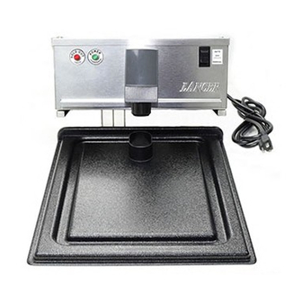
Page 3: Introduction To The Lancer Lev ® Fill Station (Lfs)
Introduction to the Lancer LEV Fill Station (LFS) ® Power Switch Power Cord, LED (Red), Three Prong, Sold Out Grounded LED (Green), Power Probe Assembly, LO Level Probe Assembly, Probe Assembly, LO Level HI Level Front View, LFS 3/8" Water Inlet 3/8"... -
Page 4: Specifications
WARNING DISCONNECT SLUSH MACHINE FROM POWER SOURCE BEFORE BEGINNING INSTALLATION OF THE LANCER LEV FILL STATION (LFS) TO AVOID POSSIBLE FATAL ® ELECTRICAL SHOCK OR SERIOUS INJURY. Base Fill Assembly Screw Mounting, Hole Pattern PN 30-3122 Figure 1 Mounting A. The dispenser is designed for in-door use ONLY and to be mounted on unit, in a well lighted, visible area. -
Page 5: Connecting To Electrical Power
CONNECTING TO ELECTRICAL POWER WARNING THIS UNIT MUST BE PROPERLY ELECTRICALLY GROUNDED TO AVOID POSSIBLE FATAL ELECTRICAL SHOCK OR SERIOUS INJURY TO THE OPERATOR. THE POWER CORD IS PROVIDED WITH A THREE PRONG GROUNDED PLUG. IF A THREE-HOLE GROUNDED ELECTRICAL OUTLET IS NOT AVAILABLE, USE AN APPROVED METHOD TO GROUND THE UNIT. -
Page 6: Operation Of The Lfs
equipment. The detergent should be caustic-based and the sanitizer should be a low pH (less than 7.0) chloride solution. B. Disconnect syrup containers and remove product from tubing by purging with water. C. Rinse the lines and fittings with clean, room temperature water to remove all traces of residual product. -
Page 7: Initial Power Up
1. Slide I.D. panel UP until flow control adjustments are exposed (see Figure 2). 2. Remove nozzle by twisting counter clockwise and pulling down. 3. Remove diffuser by pulling down. 4. Install Lancer syrup separator (PN 54-0201, smoke, for Model 145 valves) in place of the nozzle. I.D. PANEL 5. -
Page 8: Changing Syrup Package Procedure
4. Install diffuser and nozzle. 5. Slide I.D. panel (Valve Cover) down. SYRUP SYRUP WATER WATER STEMS OPEN STEMS CLOSED Mounting Block Stems in OPEN Position Mounting Block Stems in CLOSED Position FIgure 3 FIgure 4 CHANGING SYRUP PACKAGE PROCEDURE When a package of syrup is empty and the unit is in AUTO mode or MANUAL mode, the SOLD OUT light will blink and the alarm will sound until a new package is replaced as described in the following section. -
Page 9: Under Sold Out Condition, Sold Out Alarm Sounds, But The Red Sold Out Led Does Not Flash
TROUBLE CAUSE REMEDY Under SOLD OUT A. Loose connection. A. Ensure cables are secure. condition, SOLD OUT B. Polarity incorrect (cables B. Looking at terminals (LED away alarm sounds, but the crossed). from you), ensure flat side of the Red SOLD OUT LED rectangle (between the terminals) is does not flash. -
Page 10: Erratic Ratio O Brix
TROUBLE CAUSE REMEDY 6.12 Erratic Ratio Brix. A. Incoming water and/or syrup A. Check incoming water and supply not at sufficient syrup supply to ensure sufficient flowing pressure. flowing pressure. B. Foreign debris in water and/or B. Remove flow controls and clean syrup flow controls. -
Page 11: Illustrations, Parts Listings, And Wiring Diagrams
7. ILLUSTRATIONS, PARTS LISTINGS, AND WIRING DIAGRAMS CONTROL BOX ASSEMBLY, FRONT VIEW Item Part No. Description Item Part No. Description 10 06-2483 Label, Switch, LFS 51-1397 Control Box Assy, LFS 19-0181/01 , 4.5, W/O C, L, S, WH 30-3125 Cover, LFS ®... -
Page 12: Control Box Assembly, With Stainless Steel Hopper Lid, Front View
CONTROL BOX ASSEMBLY, WITH STAINLESS STEEL HOPPER LID, FRONT VIEW Item Part No. Description Item Part No. Description 51-1397 Control Box Assy, LFS 10 06-2483 Label, Switch, LFS 30-3125 Cover, LFS 19-0181/01 , 4.5, W/O C, L, S, WH ® (includes back block) 04-0148 Screw, 10 - 32 x 0.250, THD, SL,... -
Page 13: Plumbing
PLUMBING Item Part No. Description 12-0115 Switch, Pressure, Assy, Syrup Out 01-2241 Bulkhead, SS, 1/4 Barb X 3/8 FLR 01-2207 Tee, SS, 1/4 Barb x 1/4 Barb x 1/4 NPT 07-0433 Clamp, Hose, STPLS, 13.3 (1/2”) 01-0012 Adaptor, 1/4 Barb x Dole 02-0005 O-Ring, 2-010 08-0461... -
Page 14: Control Box Assembly, Rear View
CONTROL BOX ASSEMBLY, REAR VIEW WATER SYRUP Item Part No. Description Item Part No. Description 06-0112 Label, Water 11 04-1292 Washer, SS, 0.5 ID x 0.87 OD x 04-0684 Nut, Hex, 5/8 - 18, JAM, SST 0.03 THK 04-0148 Screw, 10 - 32 x 0.250, THD, SL, 12 06-0075-01 Nameplate, Vinyl, PN/SN/ELEC MS, SS... -
Page 15: Internal Components
INTERNAL COMPONENTS Item Part No. Description Item Part No. Description 52-2502 PCB Assy, LFS R 10 52-2492 Probe Assy, LO Level, LFS 05-1535 Support, PCB, 0.156 x 0.187 x R 11 52-2493 Probe Assy,, HI Level, LFS 0.25 OH R 12 25-0039 Transformer, 120V/50-60Hz, 24V, 03-0095... -
Page 16: Wiring Diagram
WIRING DIAGRAM PRESSURE SWITCH LED AWAY FLAT DOWN CONNECT RED TO RIGHT TAB PROBES SWITCH 52-2496 11-0180 52-2511 TO VALVE PC BOARD TRANSFORMER 52-2509 GRN/YEL ® 06-2486/01 WIRING DIAGRAM, FILL STATION...
Need help?
Do you have a question about the LEV FILL STATION and is the answer not in the manual?
Questions and answers