lancer 4500 Series Installation Manual
Ice beverage dispensers
Hide thumbs
Also See for 4500 Series:
- Operation manual (48 pages) ,
- Operation manual (40 pages) ,
- Installation and service manual (20 pages)
Table of Contents
Advertisement
Quick Links
IBD 22
FOR QUALIFIED INSTALLER ONLY. This basic Installation Sheet is an initial release. If a complete Operations
Manual (for the unit being installed) is required or needed, please refer to the Lancer web site (lancercorp.com) for
immediate access, or for your convenience, scan this QR code with a mobile device (app required) for immediate
access to other Technical Documents and alternative translations (if available) pertaining to this unit. Contact Lancer
Customer Service for assistance as required.
ABOUT THIS MANUAL
This booklet is an integral and essential part of the product and
should be handed over to the operator after the installation and
preserved for any further consultation that may be necessary.
Please read carefully the guidelines and warnings contained
herein as they are intended to provide the user with essential
information for the continued safe use and maintenance of the
product. In addition, it provides GUIDANCE ONLY to the user on
the correct services and site location of the unit.
The installation and relocation, if necessary, of this product must be carried out by qualified personnel with
up-to-date safety and hygiene knowledge and practical experience, in accordance with current regulations.
IMPORTANT SAFETY INSTRUCTIONS
! Intended Use
The dispenser is for indoor use only. This unit is not a toy. Children should not be supervised not to play with appliance. It should
not be used by children or infirm persons without supervision. This appliance is not intended for use by persons (including children)
with reduced physical, sensory or mental capabilities, or lack of experience and knowledge, unless they have been given
supervision or instruction concerning use of the appliance by a person responsible for their safety. Cleaning and user maintenance
shall not be performed by children without supervision. The min/max ambient operating temperature for the dispenser is 40°F to
105°F (4°C to 41°C). Do not operate unit below minimum ambient operation conditions. Should freezing occur, cease operation of
the unit and contact authorized service technician. Service, cleaning and sanitizing should be accomplished only by trained
personnel. Applicable safety precautions must be observed. Instruction warnings on the product being used must be followed.
F Electrical Warning
Check the dispenser name plate label, located behind the splash plate, for the correct electrical requirements of unit.
into a wall electrical outlet unless the current shown on the serial number plate agrees with local current available. Follow all local
electrical codes when making connections. Each dispenser must have a separate electrical circuit. Do not use extension cords with
this unit. Do not 'gang' together with other electrical devices on the same outlet. The keyswitch does not disable the line voltage to
the transformer primary. Always disconnect electrical power to the unit to prevent personal injury before attempting any internal
maintenance. The resettable breaker switch should not be used as a substitute for unplugging the dispenser from the power source
to service the unit. Only qualified personnel should service internal components of electrical control housing. Make sure that all
water lines are tight and units are dry before making any electrical connections!
®
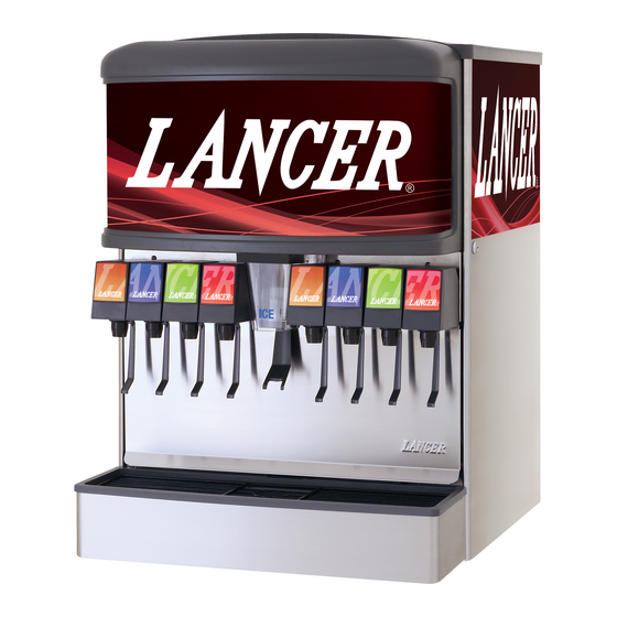
4500
Ice Beverage Dispensers - Model 4500
IBD 25
BEFORE GETTING STARTED
Each unit is tested under operating conditions and is thoroughly
inspected before shipment. At the time of shipment, the carrier
accepts responsibility for the unit. Upon receiving the unit,
carefully inspect the carton for visible damage. If damage exists,
have the carrier note the damage on the freight bill and file a
claim with carrier. Responsibility for damage to the dispenser lies
with the carrier.
LANCER INSTALLATION GUIDE
IBD 30
Do not plug
Revision: September 2018
Lancer PN: 28-0483/04
Advertisement
Table of Contents

Related Manuals for lancer 4500 Series


Summary of Contents for lancer 4500 Series
- Page 1 FOR QUALIFIED INSTALLER ONLY. This basic Installation Sheet is an initial release. If a complete Operations Manual (for the unit being installed) is required or needed, please refer to the Lancer web site (lancercorp.com) for immediate access, or for your convenience, scan this QR code with a mobile device (app required) for immediate access to other Technical Documents and alternative translations (if available) pertaining to this unit.
-
Page 2: Specifications
5 Carbon Dioxide (CO Carbon Dioxide (CO2) is a colorless, noncombustible gas with a light pungent odor. High percentages of CO • WARNING: displace oxygen in the blood. Prolonged exposure to CO can be harmful. Personnel exposed to high concentrations of CO gas will experience •... -
Page 3: Installation
This manual was developed by the Lancer Corporation as a reference for the owner/operator and installer of this dispenser. Please read this guide before installation and operation of this dispenser. If service is required please call your Lancer Service Agent or Lancer Customer Service. -
Page 4: Selecting/Preparing Counter Location
Total weight (with icemaker) for this unit could exceed 800 pounds (363.6kg). NOTE Lancer does NOT recommend the use of shaved or flake ice in the dispenser. ! ATTENTION Failure to use an ice bin thermostat will not only void Unit may be installed directly on countertop or on legs. -
Page 5: Installing Remote Syrup Pumps
Connect tubing to water source then flush water lines to Once pumps and BIB rack are installed, measure and cut check for leaks. tubing to length between the pump CO inlets, then connect tubing to all pumps. Route appropriate tubing from the remote carbonator locaton to the carbonated water inlet at the unit and connect tubing to inlet. -
Page 6: Dispenser Setup
! WARNING Installing CO Supply Connect high pressure CO regulator assembly to CO The dispenser must be properly electrically grounded cylinder or bulk system. to avoid serious injury or fatal electrical shock. The power cord has a three-prong grounded plug. If a ! ATTENTION three-hole grounded electrical outlet is not available, use an approved method to ground the unit. -
Page 7: Cut Away View
Adjusting The Ice Flow Regulator (230 V Units Only) Using a Lancer ratio cup verify water flow rate (5 oz. in 4 sec.). Use a screwdriver to adjust if needed. NOTE The Regulator Door Assembly (PN 82-2904) can regulate the dispensed ice flow. Installation of an Ice Flow Regulator is NOT necessary for the dispensing of ice. This IBD unit will dispense ice unrestricted. -
Page 8: Cleaning And Sanitizing
CLEANING AND SANITIZING General Information Other Supplies Needed • Lancer equipment (new or reconditioned) is shipped from Clean cloth towels Sanitary gloves the factory cleaned and sanitized in accordance with NSF Bucket Small brush (PN 22-0017) guidelines. The operator of the equipment must provide... -
Page 9: Cleaning And Sanitizing Syrup Lines - Bag In Box
Cleaning and Sanitizing Syrup Lines - Bag in Box Rinse nozzle and diffuser with warm water. Disconnect syrup lines from BIB’s Wash nozzle and diffuser with cleaning solution then immerse in sanitizing solution and let sit for fifteen (15) Place syrup lines, with BIB connectors, in a bucket of warm minutes. -
Page 10: Automatic Agitation And Low Ice Alarm Control
Automatic Agitation and Low Ice Alarm Control NOTE Each Series 4500 ice beverage dispenser is equipped with automatic agitation for the ice bin. The unit is shipped with timing set at two (2) seconds ON every 60 minutes. Referring to the tables on the wiring diagram (located on next page and affixed to the electrical box cover), the automatic agitation timing can be changed as follows. A set of DIP switches is provided to control the timing and low ice control. Dispensers using pellet ice must have the automatic agitation settings adjusted to four (4) seconds ON every 150 minutes. Refer to Automatic Agitation Warning on page 3. DIP# DESCRIPTION DIP#1 This switch controls the low ice indicator light. With the switch in the ON position, the light operates when a low ice condition exists. - Page 11 Wiring and Plumbing Diagrams WIRING DIAGRAM FOR LANCER ICE DISPENSER WITH LOW ICE SENSING (TYP.) Wiring Diagram - 115 Volt / 60 Hz - 22, 25, 30 Inch NOTE: NOT USED ON PREMIX DISPENSERS ELECTRICAL BOX BOUNDARY WHITE BLACK LIGHT...
- Page 12 Wiring Diagram - 230 Volt / 50-60 Hz WIRING DIAGRAM FOR LANCER ICE DISPENSER WITH LOW ICE SENSING (TYP.) NOTE: NOT USED ON PREMIX DISPENSERS ELECTRICAL BOX BOUNDARY WHITE BLACK LIGHT VALVE BLACK ALARM WHITE BLUE WHITE LOW ICE SENSOR...
Need help?
Do you have a question about the 4500 Series and is the answer not in the manual?
Questions and answers