ProMinent DULCOMETER D1C Operating Instructions Manual
Measured variable chlorine dioxide
Hide thumbs
Also See for DULCOMETER D1C:
- Operating instructions manual (33 pages) ,
- Operating instructions manual (25 pages) ,
- Operating instructions manual (28 pages)
Table of Contents
Advertisement
Quick Links
Operating Instructions
®
DULCOMETER
D1C
Part 2: Adjustment and Operation,
Measured variable chlorine dioxide
D1C2-Cl02-001-GB
Type D
Type W
___ ___ ___ ___ ___ ___ ___ ___ ___ ___ ___ ___ ___
D1C A
Please enter the identity code of your device here!
Please completely read through operating instructions! · Do not discard!
The operator shall be liable for any damages caused
by installation or operating errors.
Part No. 981734
ProMinent Dosiertechnik GmbH · 69123 Heidelberg · Germany
BA DM 151 06/07 GB
Advertisement
Table of Contents

Related Manuals for ProMinent DULCOMETER D1C


Summary of Contents for ProMinent DULCOMETER D1C
- Page 1 Please completely read through operating instructions! · Do not discard! The operator shall be liable for any damages caused by installation or operating errors. Part No. 981734 ProMinent Dosiertechnik GmbH · 69123 Heidelberg · Germany BA DM 151 06/07 GB...
-
Page 2: Device Identification / Identity Code
Device Identification / Identity Code D1C A DULCOMETER ® Controller Series D1C / Version A Type of mounting Control panel installation 96 x 96 mm Wall mounting Operating voltage 230 V 50/60 Hz 115 V 50/60 Hz 200 V 50/60 Hz (only with control panel installation) 100 V 50/60 Hz (only with control panel installation) 24 V AC/DC Measured variable... -
Page 3: Table Of Contents
• Correct measuring and metering is only possible in the case of impeccable operation of the probe. The probe has to be calibrated / checked regularly! NOTE A form “Documentation of controller settings Type D1C” is available under www.prominent.com/documentation_D1C for the purpose of documenting the controller settings. -
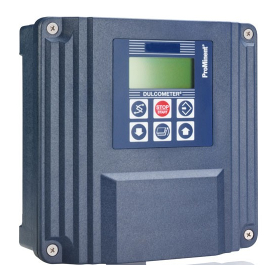
Page 4: Device Overview / Controls
Device Overview / Controls Display field Measured variable chlorine dioxide Graphic display Button "Start/Stop" Button Button "Change" "Enter" Button "Branch back" ® DULCOMETER Button Button STOP "Up" "Down" START D1C2-ClO2-002-GB CHANGE Button UP Button To change over within a menu level To increase a displayed numerical value and to change from one variable to and to change variables (flashing... -
Page 5: Functional Description
Functional Description NOTE Please refer to the description of the complete operating menu in Section 8 for a detailed ® description of the individual characteristics of the DULCOMETER D1C controller! Operating Menu The D1C controller permits settings to be made in two different menus. All values are preset and can be changed in the complete operating menu. -
Page 6: Display Symbols
Display Symbols ® The display of the DULCOMETER D1C controller uses the following symbols: Description Comment Symbol Limit value transgression Symbol Relay 1, upper left Symbol Relay 1, lower left Symbol Relay 2, upper right Symbol Relay 2, lower right Metering pump 1 (chlorine dioxide) Symbol Control off... -
Page 7: Operation
Operation The various menus are selected with Permanent the CHANGE button display 1 The menu is started with the ENTER button Permanent BRANCH BACK to permanent display display 2 or to relevant setting menu Calibration Calibration notes menu Various Access code, correct Setting menus Parameter Access code... -
Page 8: Layout
Restricted Operating Menu / Layout The restricted operating menu permits simple operation of the most important parameters. The following overview shows the settings which can be selected: Permanent display 1 0.60 auto.: 30.0 °C mea. val 0.60 ppm Permanent display 2 Positive values of setting variable: chlorine dioxide feed fwd: 70 % only with control... - Page 9 Restricted Operating Menu / Description Permanent display 1 0.60 auto.: 30.0 °C mea. val. 0.60 ppm Permanent display 2 Positive values of setting variable: chlorine dioxide feed fwd: 70 % only with control Negative values of setting variable: De-ClO ctrl out: 59 % (w = setpoint) (chlorine dioxide 0.60 ppm destruction) D1C2-ClO2-011-GB...
-
Page 10: Complete Operating Menu
Restricted Operating Menu / Description Limits Access to all setting menus can be blocked with an access code ! limits limit 2 upper setting ? 1.50 ppm limit 1 lower 0.10 ppm D1C2-ClO2-014-GB Possible values Initial value Increment Lower value Upper value Remarks Type of limit trans-... - Page 11 Restricted Operating Menu / Description Possible values Initial value Increment Lower value Upper value Remarks Setpoint 0.60 ppm 0.01 ppm lower limit upper limit 2 setpoints necessary measuring range measuring range for control with dead zone. Setpoint 1 < setpoint 2 Control parameter xp 10 % 500 %...
- Page 12 Complete Operating Menu / Overview All parameters of the controller can be set in the complete operating menu (access see previous page). The following overview shows the settings which can be selected: Permanent display 1 0.60 auto.: 30.0 °C Permanent display 2 mea. val 0.60 ppm feed fwd: 70 %...
- Page 13 Complete Operating Menu / Description Permanent display 1 0.60 auto.: 30.0 °C mea. val. 0.60 ppm Permanent display 2 Positive values of setting variable: chlorine dioxide feed fwd: 70 % only with control Negative values of setting variable: De-ClO ctrl out: 59 % (w = setpoint) (chlorine dioxide 0.60 ppm destruction) D1C2-ClO2-018-GB...
- Page 14 Complete Operating Menu / Description Error message Condition Effect Calibration ClO not possible! slope too low Calibrate again Probe slope too low (<25 % of standard slope) Calibration ClO not possible! slope too high Calibrate again Probe slope too high (>300 % of standard slope) DPD value too low DPD <2 %...
- Page 15 Complete Operating Menu / Description Measured Value Control Period IMPORTANT This function may not be activated for applications in which it can be assumed that the measured value will not change. This function tests whether the measured value changes from that of the probe (at the measured value input) within the “Measured value control period”.
- Page 16 Complete Operating Menu / Description Possible values Initial value Increment Lower value Upper value Remarks Max. stroke/minute of off = 0 strokes/min pumps 1 and 2 Relay for Power Activation Access to all setting menus can be blocked with an access code ! Only with limit value relay, solenoid valve relay or servomotor relays relay adjustment...
- Page 17 Complete Operating Menu / Description Cycle Timer relay IMPORTANT The timer will reset in the event of a power failure. ® At the end of the (timer) cycle time the DULCOMETER D1C closes the assigned relay for the duration of “t on”...
- Page 18 Complete Operating Menu / Description b) theoretical switching time > (cycle - min. time) calculated switching time < cycle Cycle Cycle Cycle min. time theoretical Cycle Cycle Cycle min. time actual ® The DULCOMETER D1C does not deactivate for a certain number of cycles until the differences between cycle and theoretical switching time exceed the “min.
- Page 19 Complete Operating Menu / Description Possible values Initial value Increment Lower value Upper value Remarks Switching direction active closed active closed Acts as N/O Limit value 1; Limit value 2 active open Acts as N/C Switch-on delay ∆t on 9999 s Switch-off delay ∆t off 9999 s If the limit is exceeded for longer than the “Delay time - limit values”...
- Page 20 Complete Operating Menu / Description Possible values Initial value Increment Lower value Upper value Remarks Servomotor Setting Setting Control direction De-ClO Control range 100 % 10 % 100 % in % of operating range NOTE • If the broad bar is to the far right, the stroke adjustment motor is fully open. •...
- Page 21 Complete Operating Menu / Description Possible values Initial value Increment Lower value Upper value Remarks Control normal normal When controlling with dead with dead zone zone, the feed forward control manual is not used for measured values within the dead zone. Setpoint 0.60 ppm 0.01 ppm...
- Page 22 Complete Operating Menu / Description Standard Signal Output 1 Access to all setting menus can be blocked with an access code ! Control with standard signal control mA output 1 Only with standard signal output regulated value: regulated value positive ClO 0 mA = mA output 1 mA output 1...
- Page 23 Complete Operating Menu / Description General setting Access to all setting menus can be blocked with an access code ! general setting identcode: D1CA alarm relay - pause normal information DxDxxxxxxxxxx active - active... closed software version - alarm off D1C-B1 FW-5.00 - td: 0 min access c.:...
- Page 24 Complete Operating Menu / Description Pause Normal ® If the pause switch is off, the DULCOMETER D1C sets the operating outputs to “0” for as long as the pause switch is off or for a set time delay t (if t is set to >...
-
Page 25: Fault / Remarks / Troubleshooting
Fault / Remarks / Troubleshooting... - Page 26 Fault / Remarks / Troubleshooting...
- Page 28 ©1995 ProMinent Dosiertechnik GmbH · D-69123 Heidelberg ® Operating Instructions DULCOMETER D1C, Part 2/Chlorine dioxide Subject to modifications · Printed in Germany ProMinent Dosiertechnik GmbH · Im Schuhmachergewann 5-11 · 69123 Heidelberg · Germany info@prominent.com · www.prominent.com...
Need help?
Do you have a question about the DULCOMETER D1C and is the answer not in the manual?
Questions and answers