ProMinent Dulcometer D1C Operating Instructions Manual
Part 2: adjustment and operation, measured variable conductivity
Hide thumbs
Also See for Dulcometer D1C:
- Operating instructions manual (33 pages) ,
- Operating instructions manual (28 pages) ,
- Operating instructions manual (25 pages)
Table of Contents
Advertisement
Quick Links
Operating Instructions
®
DULCOMETER
D1C
Part 2: Adjustment and Operation,
Measured Variable Conductivity
D1C2-Leit.-001-GB
Please completely read through operating instructions! · Do not discard!
The warranty shall be invalidated by damage caused by operating errors!
Part No. 987926
ProMinent Dosiertechnik GmbH · D-69123 Heidelberg · Germany
BA DM 085 08/01 GB
Advertisement
Table of Contents

Subscribe to Our Youtube Channel
Related Manuals for ProMinent Dulcometer D1C


Summary of Contents for ProMinent Dulcometer D1C
- Page 1 Measured Variable Conductivity D1C2-Leit.-001-GB Please completely read through operating instructions! · Do not discard! The warranty shall be invalidated by damage caused by operating errors! Part No. 987926 ProMinent Dosiertechnik GmbH · D-69123 Heidelberg · Germany BA DM 085 08/01 GB...
- Page 2 Device Identification / Identy Code D1C A DULCOMETER ® Controller Series D1C / Version A Type of mounting Control panel installation 96 x 96 mm Wall mounting Operating voltage 230 V 50/60 Hz 115 V 50/60 Hz 200 V 50/60 Hz (only with control panel installation) 100 V 50/60 Hz (only with control panel installation) 24 V AC/DC Measured variable...
-
Page 3: Table Of Contents
Contents / General User Information Page Device Identification / Identity Code ......................2 General User Information ..........................3 Device Overview / Controls ........................... 4 Functional Description ........................... 5 Display Symbols ............................. 6 Operation ................................ 7 Restricted Operating Menu ..........................8 Overview .............................. -
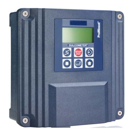
Page 4: Device Overview / Controls
Device Overview / Controls Display field Measured variable Conductivity Graphic display Push-button "Start/stop" Push-button "Change display" Push-button "Enter" Push-button "Branch back" ® DULCOMETER Push-button Push-button STOP "Up" "Down" START D1C2-Leit.-002-GB CHANGE DISPLAY menu button UP menu button To change over within a menu level To increase a displayed numerical and to change from one variable to value and to change variables... -
Page 5: Functional Description
Functional Description NOTE Please refer to the description of the complete operating menu in Section 8 for a detailed description of the individual characteristics of the D1C controller! Operating Menu The D1C controller permits settings to be made in two different menus. All values are preset and can be changed in the complete operating menu. -
Page 6: Display Symbols
Display Symbols The display of the D1C controller uses the following symbols: Description Comment Symbol Limit value transgression Symbol Relay 1, upper left Symbol Relay 1 lower left Symbol Relay 2 upper right Symbol Relay 2 lower right Metering pump 1 (Increase conductivity) Symbol Control OFF left... -
Page 7: Operation
Operation The various menus are selected with Permanent the CHANGE button display 1 The menu is started with the ENTER button Permanent BRANCH BACK to permanent display or to relevant setting menu display 2 Various Access code, correct Setting menus Parameter Access code setting... -
Page 8: Restricted Operating Menu
Restricted Operating Menu / Overview The restricted operating menu permits simple operation of the most important parameters. The following overview shows the settings which can be selected: µS/cm Permanent display 1 100 µS/cm Permanent display 2 mea val. 70 % fd. -
Page 9: Layout
Restricted Operating Menu / Layout µS/cm Permanent display 1 100 µS/cm Permanent display 2 Positive values of setting variable: Increase conductivity mea val. fd. fwd.: 70 % only with control Negative values of setting variable: Reduce conductivity 59 % reg. val.: 1000 µS/cm (w=setpoint) Only with connection on standard signal terminal... - Page 10 Restricted Operating Menu / Description µS/cm 100 µS/cm mea val. fd. fwd. 70 % 59 % reg. val. 1000 µS/cm Positive values of setting variable: Permanent display 1 Permanent display 2 Increase conductivity Negative values of setting variable: Reduce conductivity only with control (w = setpoint) D1C2-Leit.-011-GB...
- Page 11 Restricted Operating Menu / Description Possible values Initial value Increment Lower value Upper value Remarks Cellconstant cc 1.000/cm 0.0001/cm 0.0060/cm 0.1499/cm cc can be adjusted 0.001/cm 0.150/cm 1.499/cm for all mr 0.01/cm 1.50/cm 12.00/cm over the complete area The measured value can be adjusted to the actual conductivity value by changing the cell constants. The following menus apply generally! Relays for Solenoid Valve Activation Access to all setting menus can be blocked with an access code !
- Page 12 Restricted Operating Menu / Description Initial value Increment Lower value Upper value Remarks Type of limit Limit 1: lower lower transgression Limit 2: upper upper 10 µS/cm 0.01 µS/cm –1 µS/cm 21 µS/cm meas. range 20 µS/cm Limit value Limit 1: 15 µS/cm Limit 2: 25 µS/cm...
-
Page 13: Description
Restricted Operating Menu / Description Possible values Initial value Increment Lower value Upper value Remarks 10 µS/cm 0.01 µS/cm -1 µS/cm 21 µS/cm meas. range 20 µS/cm Setpoint 15 µS/cm 0.01 µS/cm -2.5 µ/Sm 52.5 µ/Scm meas. range 50 µS/cm* -10 µS/cm 210 µS/cm meas. - Page 14 Complete Operating Menu / Overview All parameters of the controller can be set in the complete operating menu. The following overview shows the settings which can be selected: Connection terminal conductive conductivity Connection terminal standard signal µS/cm µS/cm Permanent display 1 Permanent display 1 100 µS/cm Permanent display 2...
- Page 15 Complete Operating Menu / Description µS/cm Permanent display 1 100 µS/cm Permanent display 2 Positive values of setting variable: Increase conductivity mea val. 70 % fd. fwd.: only with control Negative values of setting variable: Reduce conductivity 59 % reg. val.: 1000 µS/cm (w = setpoint) D1C2-Leit.-018-GB...
- Page 16 Complete Operating Menu / Description Calibrating temperature coefficient α The temperature coefficient is a determined through two-output calibration. During the calibration procedure, metering is reduced to the set basic load. The monitoring of limiting values and error treatment are stopped. The standard signal of the output measured value or correction value is reduced to 0/4 mA.
- Page 17 Complete Operating Menu / Description Cell connection Access to all setting menus can be blocked with an access code ! change type of cell connection wire resistance final resistance 10.0 Ω connection ? 2-wire automatic connect final wire resistance 3.7 Ω resistance ! wire resistance manual...
- Page 18 Complete Operating Menu / Description Calibration conductivity with connection standard signal calibration calibration conductivity: conductivity ? 1500 µS/cm D1C2-Leit.-029-GB During calibration, metering is reduced to the set basic capacity. The standard signal of the output (measured value/correction value) is reduced to 0 mA or 4 mA. The actually measured value will be proposed;...
- Page 19 Complete Operating Menu / Description Possible values Initial value Increment Lower value Upper value Remarks 0..2000 µS/cm 0..1000 mS/cm* Measuring range setpoints and limit values 0..200 mS/cm are switched over 0..20 mS/cm to their respective 0..5000 µS/cm* initial values 0..2000 µS/cm 0..500 µS/cm* * only with connection 0..200 µS/cm...
- Page 20 Complete Operating Menu / Description The following menus apply generally Pumps Access to all setting menus can be blocked with an access code ! Only with pumps for control Control Dosing pump max. Pumps pump1: setting ? pump1 cond pump2: pump2 cond pulse/minute D1C2-Leit.-022-GB...
- Page 21 Complete Operating Menu / Description Limits Access to all setting menus can be blocked with an access code ! Limit 1 lower Limit 2 upper 1000 µS/cm 1500 µS/cm Limits setting ? Only with limit value relay Limit 1 lower Limit 2 upper 1000 µS/cm...
- Page 22 Complete Operating Menu / Description Servomotor Activation of the servomotor must be carried out with the same meticulous care as taken when calibrating a measuring probe. The operating range is defined by the total resistance range of the feedback potentiometer. The maximum limit of the range actually used is set by defining the control range. ATTENTION: To ensure correct operation, the activation time of the actuator used should not be less than 25 seconds for the control range from 0…100 %!
- Page 23 Complete Operating Menu / Description Control Access to all setting menus can be blocked with an access code ! Note: The controlled variable is recalculated every second. Only suitable for process with time constants greater than 30 s ! Only with control Positive values of setting variable: Increase conductivity Negative values of setting variable:...
- Page 24 Complete Operating Menu / Description Feed forward control feed forward feed forward ctrl. feed forward ctrl.: feed forward ctrl. setting ? control: rated value: effect: Hz / mA 10.00 Hz additiv 10 Hz feed forward ctrl. max. additive regulated value 100 % D1C2-Leit.-035-GB Possible values...
- Page 25 Complete Operating Menu / Description Standard signal output 2 Access to all setting menus can be blocked with an access code ! Control with standard signal control signal output 2 regulated value Only with 2 standard signal outputs regulated value: positive cond 0 mA = signal output 2...
-
Page 26: Complete Operating Menu
Complete Operating Menu / Description General setting Access to all setting menus can be blocked with an access code ! general setting ident-code: D1CA alarm relay control input information DxLxxxxxxxxxx active pause closed software version = active D1C-xx FW-xx.x = alarm 5000 access c.: operating menu:... -
Page 27: Ec Declaration Of Conformity
EC Declaration of Conformity... -
Page 28: 10 Troubleshooting
Operating Instructions DULCOMETER ® D1C, Part 2/L, Version 1.0, Issue 08/01 Subject to modifications · Printed in the F.R.Germany ProMinent Dosiertechnik GmbH · Im Schuhmachergewann 5-11 · 69123 Heidelberg · Germany Postfach 101760 · 69007 Heidelberg · Germany info@prominent.de · www.prominent.de...
Need help?
Do you have a question about the Dulcometer D1C and is the answer not in the manual?
Questions and answers