
Related Manuals for ECD TC80


Summary of Contents for ECD TC80
- Page 1 NSTRUCTION ANUAL TC80 T ODEL OTAL HLORINE NALYZER DC80 D ODEL ECHLORINATION NALYZER TC80 IM Rev. C...
- Page 2 Page 1 Model TC80...
-
Page 3: Screen Map
CREEN Cal 1 (Offset) using Calibration Solution Auto Cal 2 (Slope) using Calibration Solution Standardize Enter Grab Sample Determined Value (Calibration) Enter Offset, the PV value and associated mV Manual Enter Slope, mV/pH, mV/decade, mV/ppm… Temp Enter measured Temperature Temp. Format °C or °F Contrast Adj. - Page 4 PREFACE Purchasing products from Electro-Chemical Devices, Inc. provides you with the finest liquid analytical instrumentation available. If this is your first purchase from ECD, please read the entire manual before installing and commissioning your new equipment. Manuals are accessible on the ECD website at http://www.ecdi.com/literature/manuals.html...
- Page 5 Contents of this manual are believed to be correct at the time of printing and are subject to change without notice. ECD is not responsible for damage to the instrument, poor performance of the instrument or losses resulting from such, if the problems are caused by: •...
-
Page 6: Table Of Contents
1.0 GENERAL DESCRIPTION ............................. 12 1.1 FEATURES ..............................13 1.2 SPECIFICATIONS ............................. 13 1.2.1 Sensors and Flow Train ........................... 13 1.2.2 TC80 Analyzer ............................13 1.3 Model Codes ..............................14 2.0 INSTALLATION..............................15 2.1 MOUNTING ..............................15 2.2 WIRING ................................16 2.2.1 Wiring, power ............................ - Page 7 3.03 Influences on the Measurement ......................21 Temperature ..............................21 3.1 KEYS ................................22 3.1.1 Home/Exit Key ............................22 3.1.2 Back/Hold Key ............................22 3.1.3 Selection Adjustment Keys ........................22 3.1.4 Alpha Numeric Entry..........................23 3.2 MENU STRUCTURE ............................23 3.2.1 HOLD (Output Hold) ..........................
- Page 8 5.3 Constant Head Flow Controller (CHFC) ......................38 6.0 TROUBLESHOOTING ............................39 7.0 PARTS AND ACCESSORIES ..........................41 7.1 TC80 Replacement parts ..........................41 7.2 T80 Front Panel Control Board Exploded ...................... 42 7.3 T80 Front Panel Control Board Exploded, with Relays .................. 42 7.4 T80 Transmitter Case, back with Cable Glands .....................
- Page 9 ADENDUM: DC80 De-Chlorination Analyzer ......................51 DC80 Start Up Procedures ........................... 52...
-
Page 10: Terms And Conditions Of Sale
Buyer’s contracts with the U.S. Government unless Buyer has expressly acknowledged, on the face of this document, the applicability of such Regulations to the transaction between Buyer and Seller contemplated herein. Absent such acknowledgement, Seller is making the assumption in issuing this document that no such Regulations apply. Page 9 Model TC80... -
Page 11: Return Goods Policy
JURISDICTION. All such disputes shall be resolved in a court of competent jurisdiction in Orange County, California. Buyer hereby consents to the jurisdiction of the State and Federal Courts sitting in Orange County. Notwithstanding the above, should either party contest the jurisdiction of such courts, the other party may institute its suit in any court of competent jurisdiction. -
Page 12: Unpacking The Instrument
3. Save the original packing material until you are satisfied with the contents. In the event the product(s) must be returned to ECD, the packing material will allow you to properly ship it to ECD. 4. Familiarize yourself with the instrument before installation, and follow proper installation and wiring procedures. -
Page 13: General Description
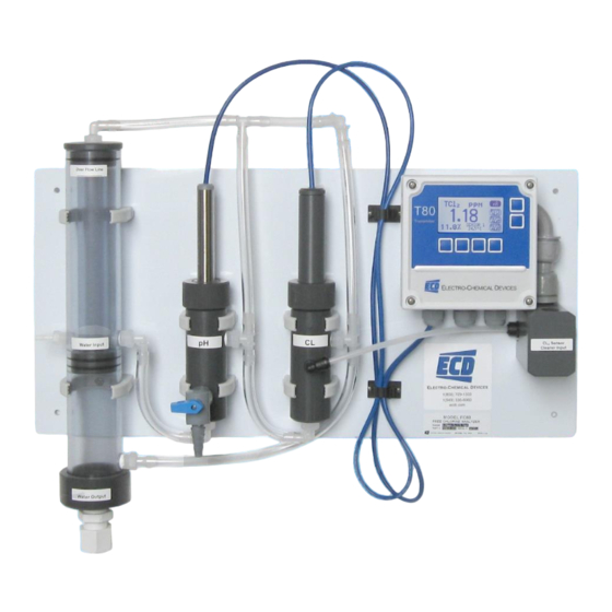
Together these compounds are referred to as Bound or Combined Chlorine. Total Chlorine is the sum of the Bound Chlorine and Free Chlorine in the sample, the TC80 measures Total Chlorine. The TC80 is a complete system for measuring Total Chlorine. The panel mounted system includes a Constant Head Flow Controller (CHFC), Total Chlorine sensor (TCS) and Flow Cell, pH sensor (S80pH) and Flow Cell and the T80 Transmitter. -
Page 14: Features
Input ¼” FNPT with barb fitting, Drain ¾” FNPT Response Time: T90 in 2 minutes Electrolyte Life: 3 to 6 months 1.2.2 TC80 A NALYZER Measurements: Chlorine: 0.00 ppb to 22.00 ppm pH: 0.00 to 14.00 pH pH Compensation of Total Chlorine:... -
Page 15: Model Codes
Flow Cell TC80- Example above shows part# TC80-01-2110, a two channel TC80 transmitter, 0.05 to 20 ppm Total Chlorine range and S80 pH sensor, 110/220 VAC powered with one 4-20 mA output with MODBUS RTU, 3 Relays (one used for... -
Page 16: Installation
Do not mount in direct sunlight or areas of extreme heat. The TC80 is suitable for outdoor use if mounted with a protective cover or sunshield. 2.1 MOUNTING The TC80 panel is drilled with 4 x 0.265” holes, one at each corner, and is designed to use ¼” -20 hardware or 6mm metric hardware. Page 15... -
Page 17: Wiring
(ANSI/NFPA-70), Canadian Electrical Code and/or any other applicable national or local codes. 2.2.1 W IRING POWER ECD recommends using a thermoplastic, outdoor sunlight resistant jacketed cable, wet location rated and ½” flexible conduit. The power should be hard wired with a switch or breaker to disconnect the analyzer from the... -
Page 18: Wiring, Sensor
IRING ENSOR The Total Chlorine Sensor and the S80 pH Sensor were connected to the TC80 analyzer at the factory, no additional connections are necessary. Color coded connections for these sensors are shown in the wiring diagrams in Section 8.3 or on the inside cover of the T80 transmitter. -
Page 19: Installing The Sensors
2.3 INSTALLING SENSORS The TC80 is supplied with the sensor cables pre-wired to the analyzer. The TC80 instrument and sensors were calibrated at the factory and should be ready for use when assembled. However, changes may have occurred during shipping and storage requiring recalibration. (See Calibration section 4.2 below) The pH sensor mounts in the Flow Cell using an o-ring sealed flange/union mount with threaded locking cap. -
Page 20: Connecting The Optional Spray Cleaner
Remove the lid from the DPC80. Connect a power cord, 110 VAC, to the Line and Neutral terminals inside the DPC 80 chlorine metering pump. Replace the lid. Mount the pump/controller near the TC80 panel. The DC80 is supplied with 10 ft. of tubing for the peristaltic pump. Lift the Tan portion of the pump from the middle to expose the rollers. -
Page 21: Operation
3.0 OPERATION This section provides a basic overview of the ECD TC80 Total Chlorine Analyzer. It covers physical and chemical influences on the measurement and the menu structure of the analyzer. 3.01 I NFLUENCES ON THE EASUREMENT ALUE The TCS measures Total Chlorine and the total chlorine concentration does not change with changes in the pH, there is always the same amount of Total Chlorine. -
Page 22: Influences On The Measurement
TCS sensor and it has a response time of several minutes. Rapid changes of temperature will introduce an error until the sensor has equilibrated to the new temperature. Calibration should be done close to the process temperature for the highest accuracy. Page 21 Model TC80... -
Page 23: Keys
3.1 KEYS The functions associated with each key are displayed on the screen, above the key for the Selection Adjustment Keys and to the left of the key for the HOME and BACK keys. Press any Selection Adjustment key twice within one second to enter the HOME Menu Screen. -
Page 24: Alpha Numeric Entry
MANUAL is a data entry screen. Manual calibration allows the user to enter a concentration with the corresponding mV value and a slope for an electrode. Laboratory generated calibration data for an electrode can be input to a remote analyzer where calibration is difficult or impractical. Page 23 Model TC80... -
Page 25: Config (Configuration Menu)
TEMP allows the displayed temperature to be trimmed to agree with actual process temperature. 3.2.3 CONFIG (C ONFIGURATION Four options are available in the Configure Menu, XMTR, SENSOR, LOAD DEFAULT and Dampen. XMTR enters the Transmitter Configuration menu. o LCD access the Display Configuration Menu ... -
Page 26: Info (Information Menu)
Sensor Screen, details the Name, Part #, Serial # and three sets of Calibration data. COMP, displays the pKa, the sensor affected and the dissociation Factor, 3.2.5 SIM (S IMULATION The Simulation menu allows the Input or Output signals to be simulated. Page 25 Model TC80... -
Page 27: Fault Screens
SYSTEM allows the Input to be simulated. Two choices are available, FIXED is a fixed value, RAMP varies the signal across the 4-20 mA range, from the lowest value to the highest value and back, activating and deactivating relays if present. -
Page 28: Configure 4-20 Ma Output Range
TIMER activates the relay periodically for a specific duration, user configured period and duration FAULT sets the relay condition to a de-energize state and NC relay closes in response to a Fault condition or power failure. Page 27 Model TC80... -
Page 29: Exit Menus And Return To Main Display
DISABLE turns off the relay and removes it’s icon from the HOME screen Setting up an Alarm Relay Choose ALARM Press CHANGE to enter new values Choose ON Set Point, Press OK Enter value using ▲ or ▼and NEXT to move to the next digit, press OK, press BACK (Min –Max values indicate the range of acceptable values) ... -
Page 30: Graphical Display
(forward →) and ▼ (backwards ←) arrows to the character of choice and then pressing NEXT to advance the cursor to the next digit. Pressing and holding the ▲ or ▼ keys will initiate two speed auto scrolling. Press BACK to exit the screen. Location: CONFIG → XMTR → LCD → LABELS → SENSOR Page 29 Model TC80... -
Page 31: Password Protection
3.4.6 P ASSWORD ROTECTION PASSWD Enter 4 character password to protect access to MENU Level, CAL Menu, CONFIG Menu and SIM Menu (simulate). Each level can be turned ON or OFF and can have a unique password. Upper Case Characters and Numbers are available for use. -
Page 32: Calibration
4.0.3 MANUAL C ALIBRATION DESCRIPTION Manual calibration allows the user to enter calibration data for an electrode into the transmitter without performing a calibration. A MANUAL Calibration requires the entry of three pieces of data, (1) A concentration Page 31 Model TC80... - Page 33 with the (2) corresponding mV and (3) a slope for the electrode. This allows laboratory generated calibration data for an electrode to be entered in a remote analyzer where calibration is difficult or impractical. The pictures show a Manual Calibration for a Total Chlorine sensor using the default values of 0.00 ppb = 0.00 mV and 8.0 nA/ppm.
-
Page 34: Ph Calibration Procedures
Leave the sensor in the process solution, take a grab sample from the process and determine the pH or place sensor in a calibration standard solution. Action Prompt Double Press any Button MENU HOME, Hold is OFF Press HOLD Hold freezes 4-20 mA Output and locks Alarm Relays during Calibration Page 33 Model TC80... -
Page 35: Total Chlorine Calibration Procedures
Cal 2. Cal 2 sets the slope of the sensor. It is accomplished by setting the ppm value of the instrument to agree with a DPD tested value of the water flowing through the TC80 Analyzer. The analyzer will suggest a corrected value of 0.00 ppm, 5.00 ppm or 10.00 ppm, which will not be correct unless that happens to be the actual value... -
Page 36: Standardize
5.00 nA/ppm Press OK Slope 5.00 nA/ppm, Accept this Value? Press YES Back to Cal Menu Press HOME Hold is ON (Press HOLD to turn off Hold) Press HOLD Turn off Hold Press EXIT Main Display Page 35 Model TC80... -
Page 37: Maintenance
5.0 MAINTENANCE The Model T80 transmitter requires no periodic maintenance, except to make sure the front window is kept clean in order to permit a clear view of the display and allow proper operation of the navigation buttons. If the window becomes soiled, clean it using a soft damp cloth or soft tissue. -
Page 38: Ph Sensor
An important aspect of sensor maintenance is the service of the electrode cartridge. After being in operation, an electrode may begin to exhibit slow response or non-reproducible measurements. This may be due to coating of the measurement electrode or clogging of the reference junction. Regular electrode cleaning reduces problems Page 37 Model TC80... -
Page 39: Ph Electrode Cartridge Cleaning
If the electrode must be left out of the process for an extended period of time, store it in a solution of water saturated with KCl or a 4.0 pH buffer solution. ECD does not recommend the storage of electrodes in distilled or deionized water. -
Page 40: Troubleshooting
6.0 TROUBLESHOOTING The TC80 was evaluated and calibrated at the factory before shipment. Upon initial start up the system should require minimal to no adjustments. Verify the system has adequate flow, greater than 10 gals /hr., the pH electrode and the temperature sensor are reading correctly. - Page 41 membrane pH indication lower than Calibrate pH sensor actual value Temperature indication is Calibrate the Temperature higher than actual value. (see Calibration) The temperature sensor lags the process temperature wait for temperature equilibrium. Zero Chlorine Reading No electrolyte in the sensor Refill Sensor Open Circuit on FCS, broken Check connector and wiring to...
-
Page 42: Parts And Accessories
7.0 PARTS AND ACCESSORIES 7.1 TC80 R EPLACEMENT PARTS Part # Description 1391005-1 Total Chlorine Sensor, High Range, 0.5 – 20.0 ppm 1391005-2 Total Chlorine Sensor, Low Range, 0.005 – 2.00 ppm 1000248 Membrane Replacement Kit (1 membrane Cap, 50 ml bottle of electrolyte ) -
Page 43: T80 Front Panel Control Board Exploded
7.2 T80 F RONT ANEL ONTROL OARD XPLODED 7.3 T80 F RONT ANEL ONTROL OARD XPLODED WITH ELAYS Item # Part # Description 9630005 Spring, Mounting Screw Set 9870621 Retaining Washer, Mounting Screw Set 3600390 8-32 x 1” SS Screw, Mounting Screw Set 3400152 Front Housing 9560005... -
Page 44: T80 Replacement Parts
Connector Plug, 4 Position (Loop, AC/DC or Hart Versions) 9090119 Connector Plug, 9 Position (AC/DC Version) 9240503-1 Front Panel Membrane Switch 9300017 Sealing ring, Cable Gland 9300034 Locking Nut, Cable Gland 9360005 Fitting, Cable Gland 9830214 Screw, Front Panel Page 43 Model TC80... -
Page 45: Appendix
APPENDIX A. A UFFER ABLES °C 4.00 7.115 10.32 4.00 7.085 10.25 4.00 7.06 10.18 4.00 7.04 10.12 4.00 7.015 10.06 4.005 7.00 10.01 4.015 6.985 9.97 4.025 6.98 9.93 4.03 6.975 9.89 4.045 6.975 9.86 4.06 6.97 9.83 4.075 6.97 4.085 6.97... -
Page 46: 0X06) Write Single Register
Baud Rate of the User Bus to the T80 (0-1200, 1- 16 bit Baud Rate 2400, 2-4800, 3-9600) Integer total message count detected by the slave (remote 16 bit BusMessage device) Integer 16 bit BusCommunicationsError total CRC error count Integer Page 45 Model TC80... - Page 47 16 bit SlaveExceptionError total count of exceptions detected Integer total messages addressed to the slave (remote 16 bit SlaveMessage device) Integer total count of messages not responded to by the 16 bit SlaveNoResponse slave (remote device) Integer total Negative Acknowledges returned by slave 16 bit SlaveNAK (remote device)
- Page 48 Current sensor value (bytes 3 and 2) Floating S80 Sensor Value (lo word) Current sensor value (bytes 1 and 0) Point 32 bit S80 Sensor Voltage (hi Corresponding sensor voltage to the sensor value Floating word) (byte 3 and byte 2) Point Page 47 Model TC80...
- Page 49 32 bit S80 Sensor Voltage (lo Corresponding sensor voltage to the sensor value Floating word) (byte 1 and byte 0) Point S80 Sensor Temperature (hi Sensor Temperature (bytes 3 and 2) 32 bit word) Floating S80 Sensor Temperature (lo Sensor Temperature (bytes 1 and 0) Point word) 16 bit...
-
Page 50: Fault Status
Meaning Measurement Decimal Hexadecimal Chemical Sensor Type Units Unknown 0000 Chemical None None Ammonia 0001 Ammonium 0002 Bromide 0003 Calcium 0004 Chloride 0005 Conductivity Conductivity 0006 Cupric 0007 Cyanide 0008 0009 % saturation 000A mg/L 000B Page 49 Model TC80... -
Page 51: Auto Spray Cleaner
LEANER The TC80 is available with an automatic spray cleaner. The cleaning cycle is controlled by Alarm Relay 1 which is configured as a TIMED relay. The default settings are a 12 hour period, 30 second duration and the HOLD function ON for the duration plus 1 minute. - Page 52 The ECD Model DC80 De-Chlorination Analyzer uses the “zero shifted” strategy. The TC80 Total chlorine Analyzer is fitted with a chlorine dosing pump that feeds into the outfall of the Constant Head Flow Controller and an “Offset”...
- Page 53 Supply chlorinated water to the TC80 and allow the reading to stabilize for at least 2 hours. The analyzer should display some non-zero value, 1-3 ppm is a good range. When the reading has stabilized record the reading and start the chlorine feed by setting the pump speed to 50.
Need help?
Do you have a question about the TC80 and is the answer not in the manual?
Questions and answers