Table of Contents
Advertisement
Advertisement
Table of Contents

Related Manuals for ECD DO82


Summary of Contents for ECD DO82
- Page 1 NSTRUCTIONAL ANUAL -DS N YDRA ITRATE NALYZER HYDRA-DS NO3 – Rev A...
-
Page 2: Able Of Ontents Preface
PREFACE Purchasing products from Electro-Chemical Devices, Inc. provides you with the finest liquid analytical instrumentation available. If this is your first purchase from ECD, please read the entire manual before installing and commissioning your new equipment. Manuals are accessible on the ECD website at https://ecdi.com/product-literature/manuals/. -
Page 3: Symbols Used In Manual
Equipment protected throughout by double insulation. Contents of this manual are believed to be correct at the time of printing and are subject to change without notice. ECD is not responsible for damage to the instrument, poor performance of the instrument or losses resulting from such, if the problems are caused by: •... -
Page 4: Table Of Contents
ABLE OF ONTENTS Preface ................................ 1 Symbols Used in Manual ..........................2 Terms and Conditions of Sale ........................6 Return Goods Policy ........................... 8 Unpacking the Instrument ......................... 9 1.0 General Description ..........................10 1.0.0 Description ..........................10 1.0.1 Chloride Ion Compensation ......................10 1.0.2 Optional pH or Ammonium Measurement ................10 1.0.3 Temperature Compensation .....................10 1.0.4 Cleaning and Maintenance .......................10... - Page 5 2.2.2 Immersion/Support Tube ......................15 2.3 Mounting ............................16 2.3.1 HYDRA Sensor Mounting ......................16 2.3.2 T80 Analyzer Mounting ......................16 2.3.3 LQ800 Controller Mounting ......................18 2.4 Wiring ..............................19 2.4.1 HYDRA-DS to T80 Transmitter ....................19 2.4.2 HYDRA-DS to LQ800 Controller....................20 2.4.3 T80 Transmitter Wiring ......................20 2.4.4 LQ800 Wiring ..........................24 3.0 Operation ............................27 3.1 T80 Transmitter ..........................27...
- Page 6 4.2.3 MANUAL Calibration Description .....................33 4.2.4 CAL (Calibration Menu) ......................33 5.0 Maintenance ............................34 5.1 Maintenance Schedule ........................34 5.2 Cleaning the Sensor ........................34 5.3 Replacing the Electrodes .........................34 6.0 Troubleshooting ..........................35 7.0 Engineering Documentation ......................36 7.1 Specifications ..........................36 7.1.1 Sensor ............................36 7.1.2 T80 Transmitter ........................36 7.1.3 Model Codes ..........................38 7.2 Installation ............................39...
-
Page 7: Terms And Conditions Of Sale
TERMS AND CONDITIONS OF SALE ACCEPTANCE. If this writing differs in any way from the terms and conditions of Buyer's order or if this writing is construed as an acceptance or as a confirmation acting as an acceptance, then Seller’s acceptance is EXPRESSLY MADE CONDITIONAL ON BUYER’S ASSENT TO ANY TERMS AND CONDITIONS CONTAINED HEREIN THAT ARE DIFFERENT FROM OR ADDITIONAL TO THOSE CONTAINED IN BUYER'S WRITING. - Page 8 FORCE MAJEURE. Seller shall not be liable for any delay in delivery, or failure to deliver, due to any cause beyond the Seller’s control including but not limited to fires, floods, or other forces of the elements; strikes, or other labor disputes; accidents to machinery;...
-
Page 9: Return Goods Policy
RETURN GOODS POLICY All requests for returned goods must be initiated through our Customer Service Department. Please call our phone number (714) 695-0051 with the specifics of your request. The following conditions must be satisfied for consideration of applicable credit for the return of products purchased from Electro-Chemical Devices: 1) The item is unused and in the original package. -
Page 10: Unpacking The Instrument
Failure to follow the proper instructions may cause damage to this instrument and warranty invalidation. Use only qualified personnel to install, operate and maintain the product. The Model DO82 Sensor should only be used with equipment that meets the relevant IEC, American or Canadian standards. ECD accepts no responsibility for the misuse of this unit. -
Page 11: 1.0 General Description
1.0 GENERAL DESCRIPTION 1.0.0 D ESCRIPTION The HYDRA-DS Nitrate Analyzer measures the concentration of dissolved nitrate ion as nitrogen (NO -N) in water. The sensor uses two electrodes to determine the NO -N concentration, a Nitrate Ion Electrode, and a Chloride Ion Electrode. An optional pH or Ammonium electrode is available for additional process information. -
Page 12: Features
1.1 F EATURES Separate, economical, easily replaceable Nitrate, Chloride, and optional pH electrodes Fast and Accurate Nitrate Measurement NO or NO Automatic compensation for Cl interference Temperature compensated NO -N measurement Rugged PVC design with removable electrode guard for easy maintenance ... -
Page 13: Hydra Dimensional Drawing
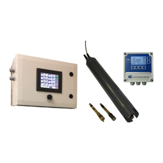
1.3 H YDRA IMENSIONAL RAWING 1.3.1 P ARTS HYDRA-DS Sensor with Electrodes, Calibration Cap 30’ of ¼” air tubing, Electrode Removal Tool HYDRA-DS NO Page 12... -
Page 14: T80 Transmitter Specifications
RANSMITTER PECIFICATIONS The ECD Model T80 transmitter is an intelligent single or dual channel multi-parameter transmitter designed for the online continuous measurement of pH, ORP, pION, conductivity, resistivity, or Dissolved Oxygen in a general purpose industrial environment. The Model T80 transmitter digitally communicates with any ECD S80 digital sensor. The measurement identity is contained in the sensor’s memory. -
Page 15: Lq800 Controller Specifications
ONTROLLER PECIFICATIONS The ECD LQ800 transmitter is a one to eight channel, intelligent, multi-parameter transmitter designed for the online continuous measurement of pH, ORP, pION, dissolved oxygen, conductivity, resistivity, turbidity, flow, level, and many others in carrying configurations for a given application. The Model LQ800 Controller digitally communicates with any ECD DS80 digital sensor, automatically configuring the transmitter’s menus and display screens to the measured... -
Page 16: 2.0 Installation
2.4.4 below. If no air supply is available use the ECD Model AC10 Air Blast Spray Cleaner compressor. The AC10 uses redundant intake air filters and redundant fuses on both the relays and the compressor. A highly reliable high current contactor assures years of trouble free service. -
Page 17: Mounting
2.3 M OUNTING 2.3.1 HYDRA S ENSOR OUNTING Install the sensor where the measured sample is representative of the entire process. Although the sensor will function in a quiescent sample, flow improves the measurement. The recommended minimum flow is 0.1 m/sec. Securely mount the HYDRA-DS sensor with the measuring end at least 6”... - Page 18 Panel Mounting Cut Out: 5.35” x (13.6cm x 13.6cm) HYDRA-DS NO Page 17...
-
Page 19: Lq800 Controller Mounting
2.3.3 LQ800 C ONTROLLER OUNTING Mount the LQ800 in a location where there is easy access to the analyzer and sensors. Install the system in an area where vibrations, electromagnetic, and radio frequency interference are minimized or absent. Do not mount in direct sunlight or areas of extreme heat (temperature >... -
Page 20: Wiring
2.4 W IRING 2.4.1 HYDRA-DS T80 T RANSMITTER HYDRA-DS NO Page 19... -
Page 21: Hydra-Ds To Lq800 Controller
2.4.2 HYDRA-DS LQ800 C ONTROLLER 2.4.3 T80 T RANSMITTER IRING Electrical wiring should only be conducted by qualified personnel. See the following T80 wiring diagrams. Figure 2.4.3.1 - Loop Powered Transmitter HYDRA-DS NO Page 20... - Page 22 Figure 2.4.3.2 - 4-Wire Transmitter, Model TR86 turbidity and Model DO82 Dissolved Oxygen sensors Figure 2.4.3.3 - 4-Wire Transmitter, 24VDC or /110/220 VAC, MODBUS, Relays/Optional Digital Preamp HYDRA-DS NO Page 21...
- Page 23 IRING OWER ECD recommends suing a thermoplastic, outdoor sunlight resistant jacketed cable, we location rated and ½” flexible conduit. The power should be hard wired with a switch or breaker to disconnect the analyzer from the main power supply. Install the switch or breaker near the analyzer and label it as the Power Switch for the analyzer.
- Page 24 110/220 VAC (4 WIRE CONFIGURATION Attach power cable as shown in Figure 2.4.3.2 or as on the diagram inside the T80 cover. Feed the sensor cable through the gland fitting on the left hand side of the T80. Do not use the same gland fitting for the AC power or the Alarm/Relays. The green terminal strip connectors are detachable from the circuit boards.
-
Page 25: Lq800 Wiring
2.4.4 LQ800 W IRING Electrical wiring should only be conducted by qualified personnel. Figure 2.4.4.1 - 110-250 VAC wiring diagram Figure 2.4.4.2 - 4-Wire Transmitter, 24VDC or /110/22 VAC, Sensor 1-8, Analog Output, Switch Input, Analog Input HYDRA-DS NO Page 24... - Page 26 Figure 2.4.4.3 - Relay Configuration WARNING: Risk of Electrical Shock Disconnect Power before opening instrument WARNING: Electrical installation must be in accordance with the National Electrical Code (ANSI/NFPA-70), Canadian Electrical Code, and/or any other applicable national or local codes. HYDRA-DS NO Page 25...
- Page 27 IRING OWER ECD recommends using a thermoplastic, outdoor sunlight resistant jacketed cable, wet location rated and ½” flexible conduit. The power should be hard wired with a switch or breaker to disconnect the analyzer from the main power supply. Install the switch or breaker near the analyzer and label it as the Power Switch for the analyzer.
-
Page 28: 3.0 Operation
3.0 OPERATION 3.1 T80 T RANSMITTER The ECD Model T80 transmitter is an intelligent, single or dual channel multi-parameter transmitter designed for the online continuous measurement of pH, ORP, pION, conductivity, resistivity or Dissolved Oxygen in a general purpose industrial environment. The Model T80 transmitter digitally communicates with any ECD S80 digital sensor. -
Page 29: Start Up Guide
3.2.2.2 A LARM Pressing the Alarm log button will give you the screen which will inform you of the triggered alarms. It will state the occurrence of the alarm, the message associated with the occurrence. Fault Definition Recommendation 3.2.2.3 CONFIG (C ONFIGURATION Three options are available in the Configure Menu, Display, Ethernet Settings, and Re-Scan Sensors. -
Page 30: 4.0 Calibration
3.2.3.1 C 4-20 ONFIGURE UTPUT ANGE 1. Press on top left hand corner of the channel box you would like to configure. Select Ao for Analog out 2. Press on the channel box to bring up the menu channel window 3. -
Page 31: Temperature Calibration
pH Calibration Solutions (optional) pH 4.01, 500 ml (Part# 2010100) or 1.00 ppm NH4-N (Part# 2010445) pH 7.00, 500 ml (Part# 2010101) or 100 ppm NH4-N (Part# 2010446) Accessories 1 liter plastic beakers Distilled Water for rinsing ... -
Page 32: Two Point Calibration
4.0.4 T OINT ALIBRATION The second point of a Two Point Calibration sets the slope of the senor, the mV per decade. The slope is calculated by comparing the millivolt values and ppm values in the “1NO3-N 1.00 ppm” line to the values in the “2NO3-N 100 ppm” line of the Buffer Menu. -
Page 33: Standardize Calibration Description
4.1.2 STAND ARDIZE ALIBRATION ESCRIPTION A Standardize Calibration is a single point calibration where the transmitter’s reading is adjusted to agree with a solution of known value, either a calibration standard, a grab sample or laboratory determined value. In many cases the constituents and the pressure and temperature of the process solution are very different from calibration solution. -
Page 34: Standardize Calibration Description
4.2.2 STAND ARDIZE ALIBRATION ESCRIPTION A Standardize Calibration is a single point calibration where the transmitter’s reading is adjusted to agree with a solution of known value, either a calibration standard, a grab sample, or a laboratory determined value. In many cases the constituents, the pressure, and the temperature of process solution are very different from the calibration solution. -
Page 35: 5.0 Maintenance
5.0 MAINTENANCE 5.1 M AINTENANCE CHEDULE The HYDRA-DS sensor requires little maintenance since most of the required cleaning is accomplished by the Air Blast Spray Cleaner. Determining the proper cleaning cycle and duration for the application will keep the front end of the sensor clean for extended periods, but weekly inspection of the sensing end is recommended. -
Page 36: 6.0 Troubleshooting
6.0 TROUBLESHOOTING Problem Possible Cause Remedy -N Reading Low Dirty Coated electrode Clean sensor: Soak in 2% HCU for 5 minutes to remove algae or rinse with weak detergent 10-15 seconds solution to remove oils. Soak in tap water for 30 minutes after either cleaning method. -
Page 37: 7.0 Engineering Documentation
7.1.2 T80 T RANSMITTER 7.1.2.1 I NPUT PECIFICATION Digital protocol, all ECD S80 sensors Optional analog to digital converter, 5 inputs [mV+, mV-, solution ground, temp + temp – (100 K-ohm)] 7.1.2.2 I NPUT ANGES -1.00 – 15.00 pH -1500 –... - Page 38 7.1.2.3 A CCURACY -1.00 – 15.00 -1500 – +1500 000.1 – 999.9, A ↔ ↔ ANGING THOUSAND 000.1 – 999.9, A ↔ 20.00 , % SAT, ISSOLVED XYGEN ANGING 0.000 – 2.000, A S ↔ S ↔ S ONDUCTIVITY ANGING µ...
-
Page 39: Model Codes
7.1.3 M ODEL ODES Model T80- (S80) S80 Digital Sensor, pH, ORP, pION, DO, DO90 ppb DO, Conductivity, Resistivity Channel Internal Preamp, Digital to S10/S17 pH, ORP, pION (+mV, -mV, 100K TC, SG) Internal Preamp, Digital to SGTC Conductivity/Resistivity (CSX2 or 2 electrode contacting) Internal Preamp, Digital to SGTC Dissolved Oxygen (Steam Sterilizable Products) 0 No Second Channel Channel... -
Page 40: Installation
7.2 I NSTALLATION 7.2.1 M OUNTING Mount the T80 in a location where there is easy access to the analyzer and sensors. Install the system in an area where vibrations, electromagnetic and radio frequency interference are minimized or absent. Do not mount in direct sunlight or areas of extreme heat (temperature >... -
Page 41: Hydra-Ds Sensor Dimensional Drawing
Cut Out: 5.35” x 5.35” (13.6 cm x 13.6 cm) 7.2 HYDRA-DS S ENSOR IMENSIONAL RAWING HYDRA-DS NO Page 40... -
Page 42: 8.0 Ordering Information
8.0 ORDERING INFORMATION 8.1 P UMBERS ODEL UMBERS Part No. Models and Products Description 1290130-3 HYDRA-DS NO3-N Digital Sensor Complete NO3, Cl-, pH, Temp, Spray Cleaner head, and 30 ft. cable 1290130-4 HYDRA-DS NO3-N Digital Sensor Complete NO3, Cl-, Temp, Spray Cleaner head, and 30 ft. cable 8.2 A CCESSORIES Part No. -
Page 43: Appendix
APPENDIX A. A UFFER ABLES °C 4.00 7.115 10.32 4.00 7.085 10.25 4.00 7.06 10.18 4.00 7.04 10.12 4.00 7.015 10.06 4.005 7.00 10.01 4.015 6.985 9.97 1.025 6.98 9.93 4.03 6.975 9.89 4.045 6.975 9.86 4.06 6.97 9.83 4.075 6.97 4.085 6.97... - Page 44 2 ALARMS ALARM CONFIG 1 Alrm 1 thresh 2 Alrm 1 hyst 3 Alrm 1 dly on 4 Alrm 2 thresh 6 Alrm 2 hyst 7 Alrm 2 dly on 8 Alrm 2 dly off 9 Alrm 3 thresh 10 Alrm 3 hyst 11 Alrm 3 dly on 12 Alrm 3 dly off 3 Address...
-
Page 45: Modbus Rtu Register Listing
C. MODBUS RTU R EGISTER ISTING 03 (0x03) Read Holding Registers This function code is used to read the contents of a contiguous block of holding registers in a remote device. The Request Protocol Data Unit specifies the starting register address and the number of registers. In the Protocol Data unit Registers are addressed starting at zero. - Page 46 Error Modbus ID (Slave Address) 1 Byte 1 to 247 (0x01 to 0xF7) Error Code 1 Byte 0x86 Exception Code 1 Byte 01, 02, 03, or 04 2 Bytes calculated Registers Per the Modbus Application Protocol Specification (V1.1b) Register # Name Meaning (2 bytes each register) Number...
- Page 47 Relay ON Setpoint (hi word) Read/Write Relay ON Setpoint (byte 3 and byte 2) 32 bit Floating Relay ON Setpoint (lo word) Read/Write Relay ON Setpoint (byte 1 and byte 0) Point Relay OFF Setpoint (hi Read/Write Relay OFF Setpoint (byte 3 and byte 2) 32 bit word) Floating...
- Page 48 S80 Serial Number (hi word) Unit Serial Number (32 bit integer hi word) 32 bit Long Integer S80 Serial Number (lo word) Unit Serial Number (32 bit integer lo word) 16 bit S80 Fault Status Integer 16 bit S80 Sensor Type Specific S80 sensor type (see S80 Sensor Types tab) Integer Specific chemicals the S80 is set to detect (see S80...
- Page 49 16 bit Sensor Abbreviated Name ASCII bytes 4 and 5 Integer 16 bit Sensor Abbreviated Name ASCII bytes 6 and 7 Integer Signals the user has completed entering the data and 16 bit Initiate S80 Storage wants it stored. Write any value. Integer Cal log number to read (0 - Cal Log 1, 1 - Cal Log 2, 2 - 16 bit...
- Page 50 0016 Turbidity TR86 0017 Turbidity TR86 0018 Turbidity TR86 0019 Turbidity TR86 mg/L 001A Turbidity TR86 % solid 001B DO82 001C DO82 % saturation 001D DO82 mg/L 001E Calcium mg/L 001F Conductivity 0020 Nitrite 0021 TCA (max range) mg/L 0022...
- Page 51 002E HP (high range) mg/L 002F HP (low percent) 0030 HP (high percent) 0031 Hardness 0032 H2SO4 (low percent) H2SO4 0033 H2SO4 (mid percent) H2SO4 0037 H2SO4 (max percent) H2SO4 0035 PAA (low range) mg/L 0036 PAA (max range) mg/L 0037 Nickel mg/L...
- Page 52 1500 North Kellogg Drive ● Anaheim, CA 92807 ● +1-714-695-0051 ● FAX +1-714-695-0057 ● ecdi.com...
Need help?
Do you have a question about the DO82 and is the answer not in the manual?
Questions and answers