
Related Manuals for ECD CA900


Summary of Contents for ECD CA900
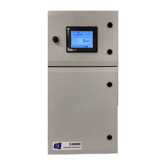
- Page 1 Instruction Manual Model CA900 Fluoride Analyzer CA900 Fluoride Analyzer Manual 4100037 Rev A...
-
Page 2: Preface
PREFACE Purchasing products from Electro-Chemical Devices, Inc. provides you with the finest liquid analytical instrumentation available. If this is your first purchase from ECD, please read the entire manual before installing and commissioning your new equipment. https://ecdi.com/product-literature/product-literature/ Manuals are accessible on the ECD website at... -
Page 3: Symbols Used In Manual
Equipment protected throughout by double insulation. Contents of this manual are believed to be correct at the time of printing and are subject to change without notice. ECD is not responsible for damage to the instrument, poor performance of the instrument or losses resulting from such, if the problems are caused by: •... -
Page 4: Return Goods Policy
If all of the above conditions are met, and the item has been approved to return to our stock, a restocking charge of 25% of the purchase price is deducted from the applicable credit CA900 Fluoride Analyzer Manual 4100037 Rev A Page 4... -
Page 5: Important Service Information
A Return Material Authorization (RMA) number must be obtained from the service department before returning any material to ECD. All material returned to ECD shall be shipped prepaid to the factory. RECEIVING THE INSTRUMENT Your Electro-Chemical Devices instrument has been carefully packaged to protect it from damage during shipment and dry storage. -
Page 6: Terms And Conditions Of Sale
California without regard to its conflict of law provisions and excluding the United Nations Convention on the International Sale of Goods. CA900 Fluoride Analyzer Manual 4100037 Rev A Page 6... -
Page 7: Table Of Contents
2.1.6.3 Chemical and waste gas hazards ......................14 3.0 Introduction – Analyzer Description..........................15 3.1 Applications................................15 3.2 Working principle: Ion Selective (ISE) using ECD Fluoride Electrode ............... 15 3.3 Analysis Cycle ................................15 3.3.1 Typical Run Sequence ..........................15 4.0 Components ................................... - Page 8 7.5.4.1 Sensor Info ............................53 7.5.4.2 System Info ............................54 7.6 Analog Outputs (4-20 mA) Configurations ....................... 55 7.6.1 4-20 mA (Process Variable, PV) ........................56 7.6.2 4-20 mA (Sensor Value) ..........................57 CA900 Fluoride Analyzer Manual 4100037 Rev A Page 8...
- Page 9 10.2.2 POLISHING ..............................70 10.3 S80/DS80 Sensor Specifications ........................... 71 10.3.1 Fluoride Electrode ............................71 11.0 Analyzer Shutdown ..............................72 Appendix A Purchasing Information ························································································································ 73 Appendix B Parts and Accessories ··························································································································· 74 CA900 Fluoride Analyzer Manual 4100037 Rev A Page 9...
-
Page 10: Overview
Appendix A Page 73. The Model CA900 Fluoride Analyzer is 100-240 VAC line powered, 50/60 Hz. Available options include, (4) 4 to 20 mA outputs, (4) configurable Relays (for Alarm, Timed Relay, and Fault), (4) digital inputs, and Ethernet communication. -
Page 11: Safety Precautions, Instructions And Hazards
Electro-Chemical Devices shall not be liable for errors contained herein and/or for the incorrect use of the analyzer. The analyzer’s users must read the User’s Manual before placing the CA900 Fluoride Analyzer into service. Observe the instructions and follow all national and local regulations and laws regarding workers health and safety. -
Page 12: List Of Warnings And Potential Dangers
Only qualified personnel, fully trained on the analyzers use and maintenance are allowed to proceed with service operations on the unit. CA900 Fluoride Analyzer Manual 4100037 Rev A Page 12... -
Page 13: Reagents
2.1.3 R EAGENTS The Model CA900 Fluoride Analyzer is based on Ion-Selective (ISE) analysis methods, using Ionic Strength Adjuster Reagent 1. For the dangers and hazards regarding the chemicals used for the analysis, refer to Chapter 6.0 Page 23 for reagent use. -
Page 14: Analyzer General Hazards
AZARDS 2.1.6.1 Electrical precautions and hazards 1. Power to the CA900 Fluoride Analyzer must be routed through an ON/OFF power switch. 2. Mind the electrical shock and/or electrocution labels placed on the analyzer. 3. All electrical devices powered by 110/220 VAC present the hazard of electrical shock or electrocution. -
Page 15: Introduction - Analyzer Description
ECD’s advanced CA900 Analyzer for Fluoride measurement is easy to install and start. All that is necessary is to perform simple connections of the sample, waste and reagent lines and then power up the factory pre-calibrated analyzer. Wall mounting hardware comes standard with each analyzer. -
Page 16: Components
4.0 COMPONENTS The CA900 Fluoride Analyzer has two distinct sections: 1. The Electrical Section including power supply, microprocessor controller, I/O and touch screen interface which are located in the Upper Compartment. 2. The Liquids Section which includes all of the liquid handling equipment and is located in the Lower compartment. -
Page 17: Electrical Section
4-20mA Analog Output and See Image 4 Digital Input Board See Image 3 Figure 1: Electrical Section Pin 2 Neutral Pin 1 Ground Pin 3 LINE Image 2: AC Input Connector CA900 Fluoride Analyzer Manual 4100037 Rev A Page 17... - Page 18 Image 4: Relay Board Four SPDT 15A 250VAC Relays Digital Inputs Analog Outputs Image 3: 4-20mA Analog Output and Digital Input Board CA900 Fluoride Analyzer Manual 4100037 Rev A Page 18...
-
Page 19: Liquids Section
In addition, the Reagent could be damaged. THE DRAIN OUTPUT MUST BE AT ATMOSPHERIC PRESSURE Failure to drain will result causing over-filling of the Reaction Cell which will cause incorrect readings and eventually Reaction Cell over-flow. CA900 Fluoride Analyzer Manual 4100037 Rev A Page 19... -
Page 20: Pumps
(screwed in to the open end of the sensor body). The sensor uses the fluoride electrode to measure the concentration. When not in use, the electrode (can be still attached to the sensor) should be kept wet with ECD booting solution (best) or at a minimum tap water. -
Page 21: Mounting
5.0 MOUNTING Mount the CA900 in a location where there is easy access to the controller and sensors, installing the system in an area where vibrations, electromagnetic, and radio frequency interference are minimized or absent. Do not mount in direct sunlight or areas of extreme heat (temperature >... -
Page 22: Wiring
Attach power cable as shown in Image 2 Page 17. Feed the cable through one of the gland fittings on the left hand side of the CA900. Tighten the cable gland to provide a good seal to the cable. The instrument can be powered up at this point with no harm to the controller, but it is best to wait until the sensor is installed. -
Page 23: Reagents And Buffers
Mind all Hazard and Poison labels. Pre-made reagents and solutions are available from ECD. The part #s for the reagents can be found in Appendix B Page CA900 Fluoride Analyzer Manual 4100037 Rev A Page 23... -
Page 24: Operation
The following are useful definitions used in the manual and are included for clarity. 1. Base Screen A – The home screen of the CA900 used to display device information. Base Screen A is where everything defaults or times out back to. -
Page 25: Colors
7.1.2 C OLORS Various colors are used on the LCD panel to convey the operation of the CA900 to the user. 1. Gray – The button or action is not available. 2. Light Blue –The parameter can be modified or denotes the current selection. -
Page 26: Popup Screens
Fluoride sensor. Once the Fluoride sensor is found, it is always polled for data and cannot be disabled. Indicates the system is initializing and will turn all green when completed. CA900 Fluoride Analyzer Manual 4100037 Rev A Page 26... -
Page 27: Base Screens
The Left and Right arrows are used to navigate between the four base screens providing views of additional system and run information. 5 inch, 640 x 480 pixel screen Main Recipe Base Screen letter designations are located at the left bottom of the screen Sensor Data Fluoride Chart CA900 Fluoride Analyzer Manual 4100037 Rev A Page 27... -
Page 28: Base Screen A (Main)
System State Indicators. Display Configuration Button Relay Indicators. One for each of the 4 Relays. Unit Title Button Ao Indicators. One for each of the 4 Analog Outputs. Base Screen Number CA900 Fluoride Analyzer Manual 4100037 Rev A Page 28... -
Page 29: Base Screen A (Main Run)
Remote Activation allows the operator to use Input 1 for activating a recipe run from another location or a button outside the housing. Input 1 can still be employed with a relay for local indication, for example CA900 Fluoride Analyzer Manual 4100037 Rev A Page 29... -
Page 30: Main Screen A (Run Continuous)
Hrs(s) = 1 Min(s) = 0 Means that every (1) hour, the analyzer will run one cycle for 5 minutes and wait an additional 55 minutes before the next cycle begins. CA900 Fluoride Analyzer Manual 4100037 Rev A Page 30... -
Page 31: Main Screen A1 (Run Recipe)
The Stop button appears Current recipe operation during a recipe run MAINT and MENU buttons are de-activated during a recipe run Stops the process and sets up the next CA900 Fluoride Analyzer Manual 4100037 Rev A Page 31... -
Page 32: Base Screenb
During a recipe run, each device turns green indicating activation. Outside of a run, each device can be pressed for manual activation of that device. Run Type Recipe Steps Current Recipe Operation CA900 Fluoride Analyzer Manual 4100037 Rev A Page 32... -
Page 33: Base Screen B (Manual Activation: Sample Pump)
Press on the Sample Pump to Manually Sample a desired quantity of Sample to the cell Press the highlighted area to enter in the desired volume to deliver Press RUN to start sampling. CA900 Fluoride Analyzer Manual 4100037 Rev A Page 33... -
Page 34: Base Screen B (Manual Activation: Reagent Pump)
This function also allows the user to prime the reagent line. Press the highlighted area to enter in the desired volume to deliver Press “RUN” to start the reagent pump/priming the reagent pump. CA900 Fluoride Analyzer Manual 4100037 Rev A Page 34... -
Page 35: Base Screen B (Manual Activation: Drain)
(best) or at a minimum tap water. If exposed to air for a long period of time, the electrode will dry out and produce erratic results. CA900 Fluoride Analyzer Manual 4100037 Rev A Page 35... -
Page 36: Base Screen B (Manual Activation: Bottle Maintenance)
7.3.2.4 Base Screen B (Manual Activation: Bottle Maintenance) Press on the Reagent Bottle to adjust name, volume and low level alarm settings. Bottle name, volume and low level alarm can be adjusted. CA900 Fluoride Analyzer Manual 4100037 Rev A Page 36... -
Page 37: Base Screen B (Manual Activation: Mixer)
7.3.3 B C (S CREEN ENSOR This base screen allows the user to view the sensor data in real time. Temperature, mV and concentration values can be observed during each recipe. CA900 Fluoride Analyzer Manual 4100037 Rev A Page 37... -
Page 38: Base Screen E (Fluoride Chart)
LUORIDE HART Past process measurement Running chart of past process measurements X and Y axis can be adjusted here. X Axis defines each reading. Y Axis defines the concentration in ppm. CA900 Fluoride Analyzer Manual 4100037 Rev A Page 38... -
Page 39: Maintenance Menu And Functions
7.4.1 M : RINSE AINTENANCE Choosing the function “RINSE” will rinse out the reaction cell and show this Warning screen. CA900 Fluoride Analyzer Manual 4100037 Rev A Page 39... -
Page 40: Maintenance Menu: Drain
7.4.2 M : DRAIN AINTENANCE Choosing the function “DRAIN” will drain out the reaction cell and show this Warning screen. CA900 Fluoride Analyzer Manual 4100037 Rev A Page 40... -
Page 41: Maintenance Menu: Store Sensor
Warning screen. Once the cell is full, the following warning screen will appear. To keep storage of sensor, leave this screen on. To end storage, press “OK”. CA900 Fluoride Analyzer Manual 4100037 Rev A Page 41... -
Page 42: Menu Functions (Menu Home Screen)
7.5 M UNCTIONS CREEN System Hold can be turned ON/OFF here. Timeout for the Menu Home screen can be set here. CA900 Fluoride Analyzer Manual 4100037 Rev A Page 42... -
Page 43: Alarm Log
Displays the occurrence and messages associated with it. Deletes all confirmed occurrences Move up and down through Deletes the the alarms. selected, confirmed Confirms the selected, recovered Confirms all recovered Selects the occurrence. occurrences CA900 Fluoride Analyzer Manual 4100037 Rev A Page 43... -
Page 44: Configure
The SYSTEM Key allows the user to configure: 1. Language 2. Bottle Maintenance 3. Display 4. Datalog 5. Ethernet Settings 6. Password 7. System Settings 8. I/O 9. Reset User Choices CA900 Fluoride Analyzer Manual 4100037 Rev A Page 44... -
Page 45: Configure (System Menu)
The Low Volume Alert Level is the volume at which a warning will be displayed. Typically, this volume should be 1 to 2 times the expected volume that will be used. Press the highlighted blue to edit. CA900 Fluoride Analyzer Manual 4100037 Rev A Page 45... -
Page 46: Display
Adjust the Display Intensity. Pressing the checkbox will change the time format between 12 and 24 hour.. Pressing the checkbox will change the calendar format between MM/DD/YYYY and DD/MM/YYYY. CA900 Fluoride Analyzer Manual 4100037 Rev A Page 46... -
Page 47: Datalog
Clears the Data and Event logs from the Clears the Data Allows the USB system memory memory stick to be eject from the system without harming any data on the stick 7.5.2.1.5 Ethernet Settings CA900 Fluoride Analyzer Manual 4100037 Rev A Page 47... -
Page 48: Password
The Configuration password can be turned on independent of the Calibration password. The respective password will be active on the next entry into the Calibrate or Configure Screens. CA900 Fluoride Analyzer Manual 4100037 Rev A Page 48... -
Page 49: System Settings
These values are configured and determined at ECD’s Factory. Recalibration must be done if any adjustments are made here. Adjust the rate(s) and press SAVE. CA900 Fluoride Analyzer Manual 4100037 Rev A Page 49... -
Page 50: I/O - Digital Inputs
The Di device can be given a descriptive Name such as “Lo Vol” in order to facilitate reading the CA900 channel with the DI device. The Di device only has to be enabled for monitoring and to start datalogging, the Di device doesn’t have to be displayed on Base Screen A for the input to be continually monitored... -
Page 51: I/O - 4-20 Ma And Relays
The red square without check mark means the warning will be displayed, whereas, the green square with the check mark means the warning will not be displayed. CA900 Fluoride Analyzer Manual 4100037 Rev A Page 51... -
Page 52: Configure (Sensor Menu)
CAL Sensor 1 allows the user to calibrate the Fluoride Sensor. Different types of calibrations are available such as automatic two point calibration, standardization, manual calibration. A temperature calibration is also found in this menu. (See Section 7.8 For the Calibration Guide) CA900 Fluoride Analyzer Manual 4100037 Rev A Page 52... -
Page 53: Information
Cal Log 2 becomes Cal Log 3 and Cal Log 3 is lost. The current calibration is then stored in Cal Log 1. Sensor Information starts with this screen Pressing the arrow buttons will move back and forth between the screens. CA900 Fluoride Analyzer Manual 4100037 Rev A Page 53... -
Page 54: System Info
Pressing the SYSTEM button will present a series of Pulldown Screens containing information on various system parameters such as firmware revisions, system serial number, Ethernet addresses and mask, relay configurations and Ao configurations. Pressing the arrow buttons will move back and forth between the screens. CA900 Fluoride Analyzer Manual 4100037 Rev A Page 54... -
Page 55: Analog Outputs (4-20 Ma) Configurations
UTPUTS ONFIGURATIONS Analog Outputs present proportional 4 to 20mA current output corresponding the signal level of any of the other CA900 devices (Sensors, Process Variable, Digital Inputs) assigned to the Ao channel. The 4 to 20mA output will correspond to the range starting and ending from the endpoints set by the user. -
Page 56: Ma (Process Variable, Pv)
A (P , PV) ROCESS ARIABLE To Simulate the 4-20 mA, adjust here and choose “RUN”. Configure the 4 and 20 mA outputs here. The user is able to Trim the mA. CA900 Fluoride Analyzer Manual 4100037 Rev A Page 56... -
Page 57: Ma (Sensor Value)
Configure the 4-20 mA for the Fluoride Sensor’s measurement. In the example, 0.00 ppT corresponds to 4.0 mA output and 2.000 ppT corresponds to 20.0 mA output. 7.6.3 4-20 A (S ENSOR EMPERATURE Configure the 4-20 mA for the Fluoride Sensor’s Temperature. CA900 Fluoride Analyzer Manual 4100037 Rev A Page 57... -
Page 58: Ma (Digital Input, Di 1-4)
A (D 1-4) IGITAL NPUT Configure the 4-20 mA for the Digital Inputs 1-4. In the example, 4.00 mA turns OFF the input and 20.0 mA will turn ON the input. CA900 Fluoride Analyzer Manual 4100037 Rev A Page 58... -
Page 59: Relay Configurations
The buttons down the right of Base Screen A will open configuration Pulldown Screens for the relay type assigned to the relay; in addition, the buttons also serve as indicators lighting up green when a relay has been activated and depict the Relay Type in plain text. CA900 Fluoride Analyzer Manual 4100037 Rev A Page 59... -
Page 60: Relay Type (Alarm)
Depending on the sensor, there will be different ranges presented with different Pulldown Screens. CA900 Fluoride Analyzer Manual 4100037 Rev A Page 60... -
Page 61: Relay Type (Alarm - Sensor 1 Value)
7.7.1.3 Relay Type (Alarm – Process Variable) The user can set an Alarm Relay for the Process Variable. The Process Variable represents the output after a full analysis cycle is completed. CA900 Fluoride Analyzer Manual 4100037 Rev A Page 61... -
Page 62: Relay Type (Alarm - Digital Input)
Timed Type relays allow for a periodic activation independent of any CA900 device set points. This feature is especially useful for spray cleaners such as the ECD AC10. The timed relay can be set to activate the spray cleaner at a running period and for a duration of sparging. -
Page 63: Relay Type (Fault)
(NO contact opens). The Fault Type operates this way as a fail-safe notification of the CA900 loss of power where the Fault Type relay will open due to loss of power. 7.7.4 R... -
Page 64: Calibration
Sensor Calibration allows the user to adjust the sensor to known values in order to compensate for wear and tear on the electrode. There are four types of calibration; AUTO, STAND, MANUAL and TEMP each of which are described in separate sections below. CA900 Fluoride Analyzer Manual 4100037 Rev A Page 64... -
Page 65: Auto Calibration
The sensor signal must be stable and Cal2. within a calculated window for 30 sec. before the calibration will continue. Pressing the light blue area brings up the Numeric Keypad allowing number entry. CA900 Fluoride Analyzer Manual 4100037 Rev A Page 65... -
Page 66: Standardize Calibration
Numeric Keypad allowing number entry. 7.8.4 T EMPERATURE ALIBRATION Temperature Calibration allows the user to correct sensor’s temperature process temperature. Pressing the light blue area brings up the Numeric Keypad allowing number entry. CA900 Fluoride Analyzer Manual 4100037 Rev A Page 66... -
Page 67: Menu And User Interface Configurations
System Hold. Pressing the light blue area allows System Hold Timeout to be selected. The light blue area indicates the current selection. Press any list item for that selection. CA900 Fluoride Analyzer Manual 4100037 Rev A Page 67... -
Page 68: Maintenance
Switch off the power to the analyzer prior to the performance of the basic maintenance work, the CA900 Fluoride Analyzer cannot be operational during maintenance. Prior to any maintenance work, take into consideration all necessary precautions regarding personal safety (protective clothing, safety glasses etc). -
Page 69: Troubleshooting
“Sensor Comm Lost” prompt Lost connection between sensor Check sensor connection to controller, loose and controller connector? Visually inspect cable for cuts or crushed areas, replace sensor if cable is compromised CA900 Fluoride Analyzer Manual 4100037 Rev A Page 69... -
Page 70: Sensor Maintenance
Frequency of cleaning will depend on the process and application. If possible, the electrode can be cleaned without removing it from the sensor body. However, if the electrode must be removed, the o-rings must be inspected and re-lubricated with the silicone grease supplied with the CA900 Fluoride Analyzer. -
Page 71: S80/Ds80 Sensor Specifications
LaF crystal Construction: PEEK body Reference Electrode: double porous Teflon junction 0.02 – 2,000 ppm Measurement range: 5 – 8 pH pH Range: 0° – 80°C Temperature Range: Pressure Range: 50 psig CA900 Fluoride Analyzer Manual 4100037 Rev A Page 71... -
Page 72: Analyzer Shutdown
11.0 ANALYZER SHUTDOWN If the CA900 Fluoride Analyzer will be out of service for a period of two weeks or greater, proceed as follows: Empty all reagent containers. Rinse and refill all reagent containers with distilled water. Prime all of the pumps with DI water. -
Page 73: Appendix A Purchasing Information
Appendix A Purchasing Information Model CA900 Fluoride Analyzer, Part # Guide CA900 Parameter Fluoride Range 0 - 50 ppm (mg/L) 0 - 200 ppm (mg/L) 0 - 1,000 ppm (mg/L) Number of Channels 1 Channel, Atmospheric Sampling Analyzer Outputs (X4) 4-20 mA, (x4) Relays, Ethernet... -
Page 74: Appendix B Parts And Accessories
FLUORIDE ELECTRODE 2000196 REACTION CELL MOTOR ASSY 2000192-1 REAGENT MICROPUMP 9600086 MAGNETIC STIR BAR 2000193 KIT FITTINGS 9551026 O-RING REACTION CELL 2000097-1 PINCH DRAIN VALVE 2000151-1 SAMPLE PUMP 1000270-2 FAST LOOP RESERVOIR CA900 Fluoride Analyzer Manual 4100037 Rev A Page 74... - Page 75 CA900 Fluoride Analyzer Manual 4100037 Rev A Page 75...
- Page 76 1500 North Kellogg Drive ● Anaheim, CA 92807 ● +1-714-695-0051 ● FAX +1-714-695-0057 ● ecdi.com...
Need help?
Do you have a question about the CA900 and is the answer not in the manual?
Questions and answers