Table of Contents
Advertisement
Quick Links
Instruction Manual
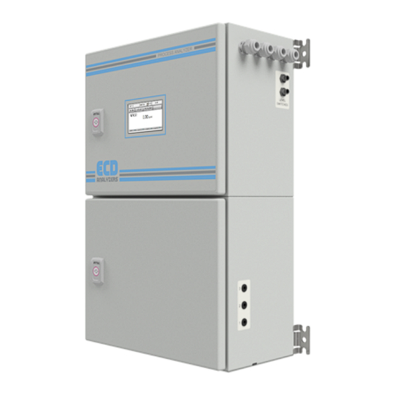
Model CA-6 Analyzer
The information and technical data disclosed in this document may be used and disseminated only for the purposes and to the
extent specifically authorized in writing by EDC Analyzers. ECD Analyzers reserves the right to change published specifications
and designs without prior notice.
Part No. CA6 IM
Rev: C – 06/21
Advertisement
Table of Contents

Related Manuals for ECD CA-6


Summary of Contents for ECD CA-6
- Page 1 The information and technical data disclosed in this document may be used and disseminated only for the purposes and to the extent specifically authorized in writing by EDC Analyzers. ECD Analyzers reserves the right to change published specifications and designs without prior notice.
-
Page 2: Preface
© 2018 ECD Analyzers LLC. All rights reserved. No part of this manual may be used or reproduced in any form or by any means, or stored in a database or retrieval system without prior written permission from ECD Analyzers LLC. Making copies of any part of this manual for any purpose other than personal use is a violation of United States copyright laws. -
Page 3: Table Of Contents
UNPACKING THE INSTRUMENT........................x 1.0 OVERVIEW ............................... 1 CONTENTS: ..............................1 0 B 1 .0.1 CA-6 Technical Specifications ....................... 2 1.1 Safety Precautions, Instructions and Hazards ..................3 1.1.1 General information ........................3 1.1.2 List of warnings and potential dangers ..................3 1.1.3 Reagents ............................ - Page 4 8.0 USER INTERFACE ........................... 32 8.1 Touch Screen Display ........................32 8.2 Passwords (****) ..........................32 8.3 Main Screen ............................ 33 8.3.1 Status Modes ..........................34 8.3.2 Menu Buttons ..........................34 8.4 RUN MENU ............................35 CA-6 Analyzers Page iv...
- Page 5 9.2 Micro Peristaltic Tubing Replacement ....................43 9.3 Cleaning the Colorimetric Cell ......................45 10.0 ANALYZER START UP AND SHUT DOWN ..................... 47 FIRST START-UP PROCEDURE ........................47 SHUT DOWN PROCEDURE ........................47 11.0 DIMENSIONAL DRAWING ........................48 CA-6 Analyzers Page v...
-
Page 6: Terms And Conditions Of Sale
4. LIMITATIONS OF LIABILITY. The following limitations of Seller's liability are acknowledged by the parties to be fair and reasonable and shall apply to any act or omission hereunder, and to any breach of this contract of which these terms and conditions form a part: CA-6 Analyzers Page vi... - Page 7 This quotation is based upon freight charges now in effect. Buyer will be invoiced at the freight charge prevailing at the date of shipment. Prices are firm for orders meeting Seller's normal shipping schedules. If shipments are held or postponed for any reason other CA-6 Analyzers Page vii...
- Page 8 County, California. Buyer hereby consents to the jurisdiction of the State and Federal Courts sitting in Orange County. Not withstanding the above, should either party contest the jurisdiction of such courts, the other party may institute its suit in any court of competent jurisdiction. CA-6 Analyzers Page viii...
-
Page 9: Returned Goods Policy
1-714-695-0051 with the specifics of your request. The following conditions must be satisfied for consideration of applicable credit for the return of products purchased from ECD Analyzers: 1) The item is unused and in the original package. -
Page 10: Important Service Information
ECDA. All material returned to ECDA shall be shipped prepaid to the factory. UNPACKING THE INSTRUMENT Your ECD Analyzers instrument has been carefully packaged to protect it from damage during shipment and dry storage. Upon receipt please follow the procedure outlined below. -
Page 11: Overview
1.0 OVERVIEW Thank you for purchasing our Model CA-6 Analyzer. The CA-6-Analyzer was designed and manufactured to be an easy-to-use, high-sensitivity and low-cost measuring instrument. This Analyzer should give you many years of reliable and hassle-free operation with regular care and maintenance. -
Page 12: .0.1 Ca-6 Technical Specifications
1 .0.1 CA-6 Technical Specifications Colorimetric parameters Analysis: Method: Photometric differential absorbance Measuring range: Contact factory for specific colorimetric measurements 5-20 minutes cycle plus wait time depending on specific Response time: measurements Repeatability: +/- 2% on absorbance value with sample turbidity < 80 NTU... -
Page 13: Safety Precautions, Instructions And Hazards
Pay attention to all Caution and Danger labels present on the analyzer and all Caution and Danger statements written in this manual. ECD Analyzers LLC shall not be liable for errors contained herein and/or for the incorrect use of the analyzer. The analyzer’s users must read the User’s Manual before placing the CA6 analyzer into service. -
Page 14: Reagents
· Reagent containers 1.1.3 Reagents The Model CA-6 Analyzer is based on colorimetric analysis methods, using chemical solutions. For the dangers and hazards regarding the chemicals used for the analysis, please contact ECDA factory. Make sure that proper safety precautions are taken (e.g. using safety gloves and glasses) during handling the chemical solutions and the reagents containers / bottles. -
Page 15: Sample Stream
1.1.6 Analyzer General Hazards 1.1.6.1 Electrical precautions and hazards Power to the CA-6 Analyzer must be routed through an ON/OFF power switch. Mind the electrical shock and/or electrocution labels placed on the analyzer. All electrical devices powered by 110/220 VAC present the hazard of electrical shock or electrocution. - Page 16 1.1.6.2 Operating precautions and hazards HAZARD: Mechanical hazards caused by moving parts such as the peristaltic pump, the motor... PREVENTIVE ACTIONS: To avoid risks the analyzer’s moving parts have been designed, built and located in an enclosure with a special key. When present inside the enclosure, these parts have protection covers to avoid any contact and physical injuries to users.
-
Page 17: Introduction - Analyzer Description
This manual provides general information regarding the principles of operation, the proper installation and operation of the CA-6 Analyzer. The Model CA-6 is an on-line sequential sampling analyzer (a sequence of sampling, analysis and result processing), using colorimetric methods. The analyzer is assembled with two separated sections with two lockable doors. -
Page 18: Absorption Photometry (Colorimetry)
Typical absorbance values range from 0 to 1, but it can be greater than 1. When the absorbance is 0 then none of the light passing through the sample is absorbed. The intensities of the sample and reference beam are both the same, so the ratio Io/I is 1. -
Page 19: Analysis Cycle
2.3 Analysis Cycle A typical Analysis Program in the Model CA-6 would have the following structure: Rinse the colorimetric reaction cell and take a sample, add one or more reagents like a buffer or masking agent and then make the first measurement, the reference measurement. The reference measurement eliminates interfering factors such as sample color and turbidity, miscellaneous color from the reagents and refractive index variations. -
Page 20: Settings
First measurement Measures the light intensity for the base reference value, in order to start from a fixed reference point and eliminate interfering factors (sample turbidity, color...). Reference function Addition of color reagent(s) Depending on the method one or more reagents may be added for the color development. -
Page 21: Programmable Functions
2.3.3 Programmable Functions Rinse #1 Rinse #1 opens the bottom pinch valve and Sample #1 flows directly to the drain. The rinsing time is set in seconds. RINSE #1 = left side of the selection valve Rinse #2 Rinse #2 opens the bottom pinch valve and Sample #2 flows directly to the drain. - Page 22 Sample #1 Sample #1 actuates the peristaltic pump with the bottom pinch valve closed and the colorimetric cell fills with sample #1. The sample time is set in seconds. SAMPLE #1 = left side of the selection valve Sample #2 Sample #2 actuates the peristaltic pump with the bottom pinch valve closed and the colorimetric cell fills with sample #2.
- Page 23 Aux on Aux On activates an optional auxiliary operation (a digestion, oxidation or auto-function for a dilution configuration). The picture shows the oxidation option (On switches the UV lamp on). Aux off Aux Off stops the optional auxiliary operation. Add rea #1 Add rea #1 turns on the micro peristaltic pump for the addition of reagent #1.
- Page 24 Add rea #3 Add rea #3 turns on the micro peristaltic pump for the addition of reagent #3. The mixing pump is circulating the sample as the reagent is being added. The Add Rea #3 time is set in seconds. Add rea #4 Add rea #4 turns on the micro peristaltic pump for the addition of reagent #4.
-
Page 25: Components
2. The Electrical Section including power supply, microprocessor controller, I/O and touch screen interface are located in the Upper Compartment. 3. Reagents Section, the CA-6 can use up to 4 reagents, these containers are typically stored below or beside the analyzer. -
Page 26: Sampling Pump
2.4.2 Sampling Pump Model CA-6 uses a Masterflex® peristaltic pump for sampling. The Model # of the pump is printed on the cover and the Model # includes the two digit tubing size designator. Proper diameter and material of the tubing must be used for proper functioning of the CA-6 Analyzer, use only ECDA replacement tubing and parts. -
Page 27: Colorimetric Reaction Cell
2.4.7 Colorimetric Reaction Cell The colorimetric reaction cell is made of glass with a diameter of 16 or 26 mm, depending on the measured parameter. The cell is located inside a thermostatic block. You can easily slide out the cell by first taking off the tubing around the cell, twist then pulling the cell straight up. -
Page 28: Options
3.0 OPTIONS Two popular options are the Dilution Module, allowing over range samples to be diluted into the proper measurement range and the Oxidation Module, used to break down complex molecules into measurable constituents. 3.1 Dilution Module For high range samples a dilution module is added to the hydraulic configuration. -
Page 29: Oxidation/Digestion Module
To ensure a complete oxidation of the sample, the oxidation can be performed using sulfuric acid, heat, UV irradiation and/or a chemical oxidizer. DANGER! Below is a list of possible hazards to be considered when the oxidation / digestion module is included in a CA-6 analyzer:... - Page 30 Hazard of chemical burns This symbol is used to represent the hazard of severe burns and serious injury from handling dangerous chemicals. All handling and maintenance operations on chemicals labeled with this symbol should be made by qualified personnel in accordance with national or local regulations.
-
Page 31: Installation
Use extreme care when lifting or moving the analyzer. If the analyzer has been in service, empty all liquids from the hydraulic parts before moving the analyzer. 4.3 Location and Mounting Instructions Install the CA-6 Analyzer in a clean, dry and dust free environment or in an enclosure with good ventilation. Environmental Operating conditions are: ... -
Page 32: Electrical Connections
Turn off the power before beginning any service on the CA-6 Analyzer. The CA-6 must be properly grounded to prevent the possibility of electrical shock. All metal surfaces are connected to the Ground terminal. The Grounding Terminal/Screw is located inside the electrical enclosure in the upper left position. -
Page 33: Ac Power Connections
The analyzer is equipped with an internal power switch (main power switch). It is recommended that the CA-6 analyzer is connected to power via a circuit breaker or an ON/OFF switch installed near the unit. - Page 34 Modbus TCP/IP Data. Connect the Analyzer to a physical network by plugging a network cable into the RJ45 jack located on the top of the enclosure. Default configuration is DHCP ON and may be changed using the analyzer configuration menus. Access the ADMIN account and select SERVICE.
- Page 35 Modbus protocol connection (Modbus RTU). This module is plugged on the control board. Use the connector provided on the board for communication.
-
Page 36: Reagents Preparation
5.0 REAGENTS PREPARATION Each analyte uses its own set of reagents to develop the distinctive color for measurement. Use good laboratory technique. Wear safety goggles, gloves and protective clothing when preparing the reagents, calibration solutions or cleaning solutions. Mind all Hazard and Poison labels Pre-made reagents and solutions are available from ECDA. -
Page 37: Analyzer Initial Start-Up
CA6 is not in use. Install the Fast Loop Reservoir(s) close to the right side of the CA-6 Analyzer. Samples and Dilution water must be drawn from atmospheric pressure. 6.1 Sample and Drain Tubing Connections After double checking Sections 4.0 & 5.0, proceed as follows: ... -
Page 38: Powering, Priming And Starting The Analyzer
reservoir to the connection on the upper right side of the CA6. 6.2 Powering, Priming and Starting the Analyzer Supply power to the analyzer. Turn ON Power Switch. The Main Menu will appear on the display. Login with the 1 level password, SERVICE (1111). -
Page 39: Calibration
7.0 CALIBRATION level password SERVICE) Colorimetry is a relative method and a calibration is needed before quantitative measurements can be performed. This is done using standard solutions and analyzing them in the same way as the samples will be analyzed. To ensure accurate measurements, the analyzer should be calibrated periodically. -
Page 40: Slope Calibration (Factor)
the sample tube in a gallon of De-ionized water, Press RUN ONLINE. After 1 hour, 5 cycles will be completed. Press RUN, Emergency Stop, RUN, RESET Emergency Stop. The analyzer will be in Standby Mode (WAIT). Press Display, Data log, average the last 3 absorbance values. Enter the average in the Blank window of the Service Menu. - Page 41 4. When the analysis cycle begins the analyzer will sample the DI water and automatically run 1 analysis cycle and then stop and enter the Stand-By (Wait) mode. Repeat 2 times. 5. After the third cycle press PROGRAM → CALIBRATION MENU key (Password protected, Service 1111) to open the calibration menu window.
-
Page 42: User Interface
8.0 USER INTERFACE 8.1 Touch Screen Display The user interface consists of the Touch Screen Display located on the front panel of the analyzer enclosure. All input/output data, information, alarms and fault conditions are shown on the display while all commands and settings may be transferred to the analyzer simply pressing the touch screen. -
Page 43: Main Screen
8.3 Main Screen The main screen displays the analyzer status, the measured parameter, reagent status and provides access to the various Menus. Analyzer type (read only window) example: Silica Analyzer, Ammonia Analyzer, Nitrite Analyzer, Phosphate Analyzer… Login **** window (two levels of password); pressing on **** the user can enter the 4 number password ... -
Page 44: Status Modes
8.3.1 Status Modes ANALYZER OPERATING STATUS The analyzer is performing a continuous set of analysis based on the steps programmed in the Analysis Cycle menu. When the analyzer completes an ON-LINE analysis cycle, it restarts a new analysis. This condition is identified as the ON-LINE condition. -
Page 45: Run Menu
8.4 RUN MENU The RUN Menu provides access to the Start /Stop functions of the analyzer, Start On-Line, Cycles to Run and Emergency Stop. 8.4.1 START ON-LINE? By pressing this button the analyzer will start a continuous cyclic analysis based on the steps set in the Analysis Cycle of the PROGRAM menu. -
Page 46: Display Menu
8.5 DISPLAY MENU 8.5.1 Display Process Values The following is a list of the displayed parameters in this menu (read only values) Sensor: Displays the current measurement of the sensor Refer: Displays the saved reference value, typically set to 9.00. (first point for the absorbance calculation) Reading: Displays the saved reading of the sensor that was used for the absorbance calculation. -
Page 47: Program Menu
8.6 PROGRAM MENU Menu Functions: Allows the user to program the 30 steps available in the Analysis Cycle Analysis Cycle. This function is protected with the 2 level password. Allows the user to program the 30 steps available in the Extra Cycle Extra Cycle. -
Page 48: Extra Cycle
8.6.2 Extra Cycle Program the 30 available steps with the function and the time in seconds. 8.6.3 Settings Menu Cycles Ratio: Program the ratio of the ANALYSIS CYCLES versus the EXTRA CYCLES (for example ANALYSIS 20 & EXTRA CYCLE 1 means that every 20 ANALYSIS CYCLEs the analyzer will perform 1 EXTRA CYCLE. Result alarm: Program the low / high alarm value. -
Page 49: Service Menu
8.7 SERVICE MENU This menu is protected with a 2 level password and contains settings critical to the performance of the analyzer. These values should only be modified by properly trained personnel. Service Window #1 Unit: Choose the unit of measurement: ppm or ppb. -
Page 50: Method Of Operation
programmed value, Hi/Low Alarm, refer to 8.6.3 Settings menu Result Alarm) Latch / Unlatch (Activate a programmed relay with toggle switch.) Service Window #2 Dual Stream: Yes/No. Cal. factor: allows the user to enter a Calibration Factor manually into the analyzer (see section 7.2). -
Page 51: Maintenance
9.0 MAINTENANCE Basic maintenance on the CA-6 Analyzer requires refilling or replacing reagent containers and cleaning the colorimetric cell on a regular basis. In addition we advise that you perform an overall visual check of the wetted parts for any leakage. If any leaks are detected, take immediate corrective action. -
Page 52: Every 4-6 Months
Replace Reagent(s) and reset reagent counters Verify Micro Peristaltic pumps are primed and pumping Run Calibrations: Blank with DI water, Slope with calibration solution 9.0.3 Every 4-6 months (depending on applications) Replace Peristaltic Pump tubing Manually clean 3 Way Valve(s), with a syringe Clean Loop Valve (option) with a syringe Replace Colorimetric Cell o-ring Hydraulics tubing replacement... -
Page 53: Micro Peristaltic Tubing Replacement
possible. Tubing is now positioned in the pump head body. With the key firmly pressed against the rotor, push down while turning counter clockwise until tubing is seated around the rotor. The tubing is now in place. Remove key and position other pump half into the rotor shaft and ... - Page 54 9. Position the tubing and fittings deep into the pump head body. 10. Using Manual Mode, activate the peristaltic pump for 1 second and insert one roller at a time in the free position (where the roller is not in contact with the tubing).
-
Page 55: Cleaning The Colorimetric Cell
9.3 Cleaning the Colorimetric Cell To determine whether the test cell needs cleaning, perform a check of the sensor voltage when DI water is present in the cell If the sensor value is below 8, perform a manual clean of the test cell prior to changing the LED voltage. To clean the cell, disconnect all tubes connected to the cell, then rotate it as appropriate to ensure any entry/exit points from the cell can pass through the block without force being applied. - Page 56 On removal, clean the cell with a small soft brush, deionized water and in the case of severe staining, some dilute acid. 9.4 Spare Parts and Accessories Contact ECDA factory or your local Rep for Part numbers of accessories and spare parts.
-
Page 57: Analyzer Start Up And Shut Down
This will ensure that the light is passing through the glass cell. ** SHUT DOWN PROCEDURE If the CA-6 Analyzer will be out of service for a period of two weeks or greater, proceed as follows: Empty all reagent containers. -
Page 58: Dimensional Drawing
11.0 DIMENSIONAL DRAWING... - Page 60 ●1500 N Kellogg Dr ● Anaheim, CA 92807 ● +1-714-695-0051● FAX +1-714-695-0057 ●ECDAnalyzers.com...
Need help?
Do you have a question about the CA-6 and is the answer not in the manual?
Questions and answers