Table of Contents
Advertisement
Quick Links
FCA‐22 Instruction Manual
Free Chlorine Analyzer/Controller
The information and technical data disclosed in this document may be used and disseminated only for the purposes and to the
extent specifically authorized in writing by Electro-Chemical Devices. Electro-Chemical Devices reserves the right to change
published specifications and designs without prior notice.
Part No. 33FCA-22 Revision A
A/05-08
Advertisement
Table of Contents

Related Manuals for ECD FCA-22


Summary of Contents for ECD FCA-22
- Page 1 FCA‐22 Instruction Manual Free Chlorine Analyzer/Controller The information and technical data disclosed in this document may be used and disseminated only for the purposes and to the extent specifically authorized in writing by Electro-Chemical Devices. Electro-Chemical Devices reserves the right to change ...
-
Page 2: Table Of Contents
FCA‐22 Instruction Manual Table of Contents General Description Product Drawing 3 Applications 4 Components ... -
Page 3: General Description
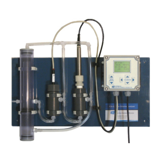
FCA‐22 Instruction Manual eneral Description FCA‐22 Components (from Left to Right) Constant Head Flow Controller Free Chlorine Sensor in Flow Cell pH Sensor in Flow Cell C‐22 Analyzer/Controller Part # Model and Product Description 1290020‐1 Free Chlorine Analyzer, with automatic pH compensation, complete assembly, panel mounted with C‐22 transmitter/controller 1290020‐2 Free Chlorine Analyzer, with manual pH compensation, complete assembly, panel mounted with C‐22 transmitter/controller Page 3 ... -
Page 4: Applications
FCA‐22 Instruction Manual General Description Application The FCA‐22 is designed for use in drinking water, industrial cooling and rinse water or other samples of fresh water that use chlorine in the range of 0‐20 ppm as a disinfectant. Chlorine exists in water as a pH dependent mixture of hypochlorous acid and hypochlorite ion. The sum of these two components is referred to as Free Chlorine, sometimes Residual Free Chlorine. Organic chlorine compounds and chloramines, Bound Chlorine, are not detected by the FCA‐22. Other measurement techniques are required for samples containing these bound chlorine chemicals. Bound Chlorine plus Free Chlorine equals Total Chlorine. The FCA‐22 does not measure Total Chlorine. Parts The ... -
Page 5: Influences On The Measurement
FCA‐22 Instruction Manual Influences on the Measurement pH Value The FCS only measures the HOCl component of the total Free Chlorine. The HOCl proportion varies from 100% at pH 5.5 to 0% at pH 10, see Figure 2.1. The PHS10 pH sensor provides automatic compensation ‐ for the pH dependent ratio of HOCl and OCl present in the water. The PTFE membrane rejects charged ions allowing only neutral molecules to pass through. Salts and other ionic substances are blocked by the membrane eliminating any influence on the measurement by changes in the conductivity of the sample. The HOCl portion of the free chlorine passes through the ‐... -
Page 6: Flow Rate
FCA‐22 Instruction Manual FCA Flow dependence % output Flowrate, gal/hr Figure 2.2 Temperature Temperature variation influences the FCS by changing the permeability of the PTFE membrane and the Nernstian response of the sensor. Combined these changes account for a change of 4% / C°. The change follows the temperature, as the temperature increases the output of the sensor increases, as the temperature drops the output drops. The FCA‐22 automatically compensates for the changes. The temperature ... -
Page 7: Installation And Start Up
FCA‐22 Instruction Manual Installation and Start Up General Information Mount the FCA‐22 in a location where there is easy access to the analyzer and sensors. Install the system in an area where vibrations, electromagnetic and radio frequency interference are minimized or absent. Do not mount in direct sunlight or areas of extreme heat. The FCA‐22 is suitable for outdoor use if mounted with a protective cover or sunshield. ... -
Page 8: Start Up
FCA‐22 Instruction Manual Start Up Supply sample flow to the system. Adjust the sample flow until the water is overflowing into the central overflow tube. At higher flow rates the excess water will overflow down the drain. A minimum flow of 10 gal/min is required to maintain the overflow condition. Verify the sample flow is passing through both flow cells and returning to the drain. The Chlorine Sensor requires 1‐1 ½ hours of polarization by the instrument before accurate measurements can be made. Allow the system to run at least 1 hour before proceeding to the Chlorine Sensor calibration below. ... -
Page 9: Ph Sensor
FCA‐22 Instruction Manual #7 Accept the calibration #8 Return to Home Press the MENU SELECT Screen down key to accept the Press the CALIBRATE new value down key to return to the Home Screen. pH Calibration The PHS10 pH sensor was calibrated with pH 7.0 and pH 10.0 buffers at the factory before shipping. Verify the displayed pH agrees with the actual pH. If the pH value deviates by more than 0.2 pH then adjust the value in the Buffer: #1 pH: Menu by setting the existing pH 7 value to the actual sample value and then accepting the calibration. For a detailed description see Electrode Standardization in the C‐22 manual. ... -
Page 10: Chlorine Sensor
FCA‐22 Instruction Manual #6 Accept the Calibration #7 Move to Second Buffer Accept the calibration by pressing the Menu Select Press Menu Select down key. Cal mV indicates Down button twice. the sensors output in 7 buffer. #8 Slope Calibration #9 Adjust Buffer Value Initiate the calibration by Use the horizontal simultaneously pressing CALIBRATE key to select the the horizontal CALIBRATE digit to be adjusted. keys with the sensor in a 10.00 pH solution or adjust to a different buffer. #10 Adjust Buffer Value Use the vertical CALIBRATE key to adjust the value and #11 Adjust Buffer Value then use the horizontal Use the vertical CALIBRATE CALIBRATE key to select ... - Page 11 FCA‐22 Instruction Manual Perform a DPD test on the sample and enter the measured ppm Cl value in the Buffer: #2 ppm Menu and accept the calibration. The displayed Cal value, x.xx mV/ppm Cl will change to the new slope value. For a detailed description see Electrode Span Calibration in the C‐22 manual. **Record the displayed Cl ppm reading at the sample time, if the value has changed before finishing the DPD test then correct the input value appropriately**. The zero point of the sensor is extremely stable and should not need adjusting. If the calibration is needed then place the sensor in a sample of chlorine free process water and allow it to equilibrate for ½ hour. Initiate the standardization in the Buffer: #1 ppm Menu. The Standardize Value will be 0.00 ppm and the Cal value will display the new mV signal from the sensor. Chlorine Calibration Screen Shots #1 Home Screen #2 Graphical Display ...
-
Page 12: Ma Output
FCA‐22 Instruction Manual #9 Setting the Chlorine #10 Adjusting the Value ppm Adjust the numeric value Use the horizontal with the vertical CALIBRATE CALIBRATE key to select the keys. Adjust largest digit digit to be adjusted. Set the first. screen value to the DPD test reading. #12 Adjusting the Value #11 Adjusting the Value Adjust the numeric value Move to the next digit to be with the vertical CALIBRATE adjusted with the horizontal keys. Calibrate keys. Once the value has been set the analyzer reading will stabilize. #14 Return to the Home #13 Accepting the Screen Calibration Leave the Calibration Screen Accept the calibration by and return to the Home pressing the Menu Select Screen by pressing the ... - Page 13 FCA‐22 Instruction Manual Choose Set up Menu #4 #3 Selection Menu To initiate the Set up Menu Press Menu Select Simultaneously press both Down button Horizontal CALIBRATE keys #5 Define Plot #6 Sample Rate (Graphical Display) (Graphical Display) Press Menu Select Press Menu Select Down button Down button #8 Adjusting 4 mA value #7 Output Range Factory setting is 0.00 ppm 4 mA value Any value can be entered using the CALIBRATE keys To initiate the 4 mA value Press the Menu Select Simultaneously press both down key to accept the Horizontal CALIBRATE keys value ...
-
Page 14: Assigning & Setting Relays
FCA‐22 Instruction Manual Alarm Relays The FCA‐22 has two assignable relays. Both relays are set to “unused” by the factory unless specified otherwise by the customer at the time of order. The SPDT relays are fully configurable, see C‐22 manual for a more detailed description. The Relays must be first assigned in the Configure/Trim Menu and then configured in the Step Up Menu. Follow the example below for guidelines on assigning and configuring the relays. Screen Shots for Assigning the Alarm Relays #1 Home Screen #2 Graphical Display Press Menu Select Press Menu Select Down button Down button #3 Selection Menu #4Selection Menu Buffer Set up Press Menu Select Press Menu Select Down button Down button #5 Selection Menu #6 Configure/Trim Menu Status To enter the Configure Press Menu Select Menu Simultaneously press Down button both Horizontal CALIBRATE ... - Page 15 FCA‐22 Instruction Manual #11 Relay Assignment/Test #12 Access Relay 1 menu To assign functions to the To access the menu relays simultaneously press Simultaneously press both both horizontal CALIBRATE Horizontal CALIBRATE keys keys #13 Assign Relay 1 to #14 Accept PV1 Chlorine To accept the change Press the Up CALIBRATE key press Menu Select to access PV1, down button PV1 = Chlorine #16 Access Relay 2 menu #15 Select Relay 2 To access the menu Press Menu Select Simultaneously press both Down button Horizontal CALIBRATE keys #17 Assign Relay 2 #18 Assign Relay 2 Press the down CALIBRATE (Missing) key to access PV2, PV2 = pH ...
- Page 16 FCA‐22 Instruction Manual Setting the Relays #1 Ch 1 Set up Menu The relays are found in the #2 Plot Screen Set up menu of the channel Press Menu Select to which they were assigned Down button, twice Simultaneously press both Horizontal CALIBRATE keys to access the menu. #4 Relay 1 Set up Screen 1 On = Set Point #3 mA Range Screen 1 Off = Hysteresis point Press Menu Select To access the menu Down button, twice Simultaneously press both Horizontal CALIBRATE keys #6 Set High/ Low Alarm #5 Choose High/Low Alarm Press the down CALIBRATE Press the horizontal key to change to <. Notice CALIBRATE key to move the the Hysteresis sign also cursor under the >. changed. #7 Low Alarm value #8 Low Alarm Value ...
- Page 17 FCA‐22 Instruction Manual #14 Adjust the value #13 Adjust the Value Press the horizontal Press the vertical CALIBRATE CALIBRATE key to move the keys to adjust the value cursor under the digit to be changed. #16 Accept Hysteresis #15 Adjust the value Value Press the vertical CALIBRATE Press Menu Select keys to adjust the value Down button # 17 Choose Relay 2 #18 Set High alarm Press Menu Select Simultaneously press both Down button Horizontal CALIBRATE keys #19 Adjust the values #20 Adjust and Save the Press the horizontal value CALIBRATE key to move the cursor under the digit to be Same as Steps 8‐9 changed. ...
-
Page 18: Maintenance
FCA‐22 Instruction Manual Maintenance Free Chlorine Sensor Check the measurement at regular intervals, at least once a month. If the membrane is visibly soiled clean it with a jet of water or a dilute HCl solution between 1‐5%. Do not clean with detergents or solvents that would reduce the surface tension of the membrane. ... -
Page 19: Ph Sensor
FCA‐22 Instruction Manual pH Sensor When used in clean water, pH sensors require little maintenance. pH sensors do require periodic calibration due to drift in the reference electrode as it ages. This aging causes the displayed pH value to be higher than the true pH of the sample. Check the sensor on a monthly basis, recalibrate if necessary. Clean or replace the pH sensor when it becomes noisy and slow to respond. ... -
Page 20: Troubleshooting
FCA‐22 Instruction Manual Troubleshooting The FCA‐22 was evaluated and calibrated at the factory before shipment. Upon initial start up the system should require minimal to no adjustments. Verify the system has adequate flow, greater than 10 gals /hr, the pH electrode and the temperature sensor are reading correctly. These parameters effect the measurement and must meet the standards ... - Page 21 FCA‐22 Instruction Manual Displayed value is Lower than Low tension on the Verify the Measuring DPD test value (cont’d) membrane Chamber is fully tightened onto the body or replace membrane. Flow to low through the flow Clean CHFC, fittings and cell tubing, verify the sample feed rate at +10 gal/hr. Air bubbles trapped on Loosen FCS fitting and lift membrane sensor slightly to purge air trapped in the flow cell. Air bubble inside the sensor Refill sensor, see Maintenance between cathode and membrane ...
-
Page 22: Product Specifications
FCA‐22 Instruction Manual Product Specifications Sensors and Flow Train C‐22 Analyzer FCS (Free Chlorine Sensor) Measurements Polarographic electrode, Gold cathode and Chlorine 0.00 to 20 ppm Silver anode, PTFE membrane pH 0 – 14 pH Temperature 0° to 100° C (32°‐212°F) PHD10 (pH sensor) Combined sensor, pH glass electrode, KCl/AgCl /pH Compensation Between pH 5‐9 reference electrode with porous Teflon junction, 3 K‐ohm temperature sensor and Display 2.5” X 1.75” backlit LCD signal conditioner 4 lines of text and Graphical Measurement Range Case NEMA 4X, LxWxD 5.7” x Chlorine ... -
Page 23: Spare Parts
2. Connected, installed, adjusted or otherwise used not in accordance with the instructions furnished by ECD; 3. Repaired, modified or altered by persons not authorized by ECD, resulting in injury to the performance, stability or reliability of the product. This warranty is in lieu of any other warranty, expressed or implied. ECD reserves the right to make changes in the design or construction of its products at any time, without prior notification, and without incurring any obligation to make any changes in previously delivered products. ... - Page 24 FCA‐22 Instruction Manual Service Department at: (800) 729‐1333 or (714) 692‐1333 or e‐mail to Service@ecdi.com or through the ECD web page, www.ECDI.com. A Return Material Authorization (RMA) number must be obtained from the service department before returning any material to ECD. All material returned to ECD shall be shipped prepaid to the factory. Ship to: Contact Info: Phone: +1‐714‐692‐1333 Electro‐Chemical Devices, Inc. +1‐800‐729‐1333 23665 Via Del Rio FAX: +1‐714‐692‐1222 Yorba Linda, CA, USA 92887‐2715 Email: sales@ecdi.com service@ecdi.com Website: www.ecdi.com Page 24 ...