Table of Contents
Advertisement
Quick Links
ETC Installation Guide
Unison Paradigm
Overview
The Unison Paradigm
utilizes passive infrared (PIR) technology, providing reliable vacancy and
occupancy detection for lighting control. Paradigm Occupancy Sensors
integrate with Paradigm lighting control systems, providing energy efficient
lighting control solutions.
Each sensor is available in neutral white or black finish. Lens masks are
provided to allow customized occupancy detection fields as required by each
installation.
Wire Specification
The Paradigm Occupancy Sensor utilizes LinkConnect to power the sensor and
to provide data to and from the connected Paradigm control system.
LinkConnect is topology-free and polarity independent. You can install your
data runs in any desired combination of bus, star, loop, and home-run. ETC
recommends using Belden 8471 (or equivalent) wire. The total combined
length of a LinkConnect wire run may not exceed 1,640 feet (500m), with a
maximum distance of 1,312 feet (400m) between any two devices.
Note:
All control wiring should be installed and terminated by a qualified installer
and should follow standard wiring installation practices and meet local codes.
Leave approximately 10 inches (254mm) of wiring in the junction box or tied
back in the ceiling to allow for wiring connections and future service needs.
Corporate Headquarters
London, UK
Tel +44 (0)20 8896 1000
Rome, IT
Tel +39 (06) 32 111 683
Holzkirchen, DE
Tel +49 (80 24) 47 00-0
Hong Kong
Tel +852 2799 1220
Web:
www.etcconnect.com
Product information and specifications subject to change.
7184M2160
Rev C
Released 2016-07
Occupancy Sensor Installation Guide
®
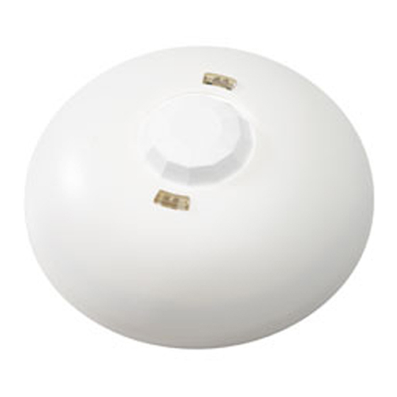
Occupancy Sensor
®
Occupancy Sensor is a ceiling mounted sensor that
The Paradigm Occupancy Sensor provides 360 degree coverage
of the installed location and is available in three models:
• P-OCC-SR- Occupancy Sensor with small room lens
covers 450 sq. ft. at 8 ft. (41.8m
12 ft (74.3m
• P-OCC - Occupancy Sensor with standard room lens
covers 1,800 sq. ft. at 8 ft. (167m
at 12 ft. (279m
• P-OCC-HC - Occupancy Sensor with high ceiling lens
covers 350 sq. ft. at 12 ft. (32.5m
at 40 ft. (650m
ETC requires that all sensors be grounded by using a 14 AWG
2
(2.5mm
) ESD drain wire.
Middleton, Wisconsin, USA
Service: (UK)
Service: (UK)
service@etceurope.com
Service: (DE)
Service: (Asia)
service@etcasia.com
Copyright © 2016 ETC. All Rights Reserved.
2
at 6.65m).
2
at 6.65m).
2
at 12.2m)
Tel +608 831 4116
service@etceurope.com
techserv-hoki@etcconnect.com
ETC intends this document to be provided in its entirety.
Page 1 of 8
2
at 2.4m) / 800 sq. ft. at
2
at 2.4m)/ 3,000 sq. ft.
2
at 2.4m)/ 7,000 sq. ft.
Service: (Americas)
service@etcconnect.com
Electronic Theatre Controls, Inc.
Advertisement
Table of Contents

Related Manuals for ETC P-OCC-SR


Summary of Contents for ETC P-OCC-SR
- Page 1 Paradigm control system. LinkConnect is topology-free and polarity independent. You can install your data runs in any desired combination of bus, star, loop, and home-run. ETC recommends using Belden 8471 (or equivalent) wire. The total combined length of a LinkConnect wire run may not exceed 1,640 feet (500m), with a maximum distance of 1,312 feet (400m) between any two devices.
-
Page 2: Installation Environment
ETC recommends paying special attention to the installation environment: • The sensor must have an unobstructed view of the room. Do not mount behind or near tall cabinets, shelves, hanging light fixtures, etc. • Do not install the sensor within eight feet from an HVAC airflow duct / vent. -
Page 3: Junction Box Installation
ETC Installation Guide Occupancy Sensor Junction Box Installation Step 1: Pull the Belden 8471 (or equivalent) and 14 AWG (2.5mm ) ground wire to the junction box. terminate wires here If you are installing the sensor in series with other sensors... -
Page 4: Soft Ceiling Tile Installation
ETC Installation Guide Occupancy Sensor Step 5: Strip each wire 5/16” (8mm) and terminate the white, black, and green (ground) wires to the terminal block located on the sensor control board. Torque each termination to 3.1-3.5 in-lb. a: Terminate the white incoming wire to terminal A. -
Page 5: Lens Masking
ETC Installation Guide Occupancy Sensor If you are installing the sensor in series with other sensors Step 4: or stations (continuing the data run), use the provided LinkConnect pigtail, ESD ground wire pigtail and WAGO connectors to make the terminations. If you are not continuing the data run, proceed to step 5. -
Page 6: Power Up And Test
ETC Installation Guide Occupancy Sensor Power Up and Test Power Up For power to be applied to the Paradigm Occupancy Sensor, any additional LinkConnect terminations for the system must also be made. In addition, the Paradigm Architectural Control Processor (P-ACP) and Station Power Module (P-SPM) must be installed in the host DRd or ERn rack enclosure. - Page 7 ETC Installation Guide Occupancy Sensor Enable Walk Test Mode Step 1: Prepare the site for configuration. a: Make certain the sensor and lighting loads are powered and connected for control by the Paradigm control system. b: You will need direct access to the Paradigm Occupancy Sensor in order to place it into walk test mode.
- Page 8 ETC Installation Guide Occupancy Sensor Verify Vacancy Operation For systems that have been configured for the installed sensor to control specific lighting circuits, walk test mode can also be used to verify vacancy operation. Step 1: Confirm the installing technician has programmed the lighting control system.