Table of Contents
Advertisement
Quick Links
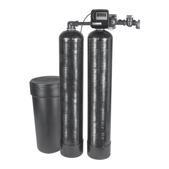
PWSRTA Twin Alternating Series Softeners
Installation, Operation
and Maintenance Manual
PWSRTA Twin Alternating Softener
!
WARNING
Read this Manual BEFORE using this equipment.
Failure to read and follow all safety and use information can
result in death, serious personal injury, property damage, or
damage to the equipment.
Keep this Manual for future reference.
!
WARNING
You are required to consult the local building and plumbing
codes prior to installation. If the information in this manual
is not consistent with local building or plumbing codes,
the local codes should be followed. Inquire with governing
authorities for additional local requirements.
WARNING
!
Need for Periodic Inspection/Maintenance: This product must
be tested periodically in compliance with local codes, but at least
once per year or more as service conditions warrant. All prod-
ucts must be retested once maintenance has been performed.
Corrosive water conditions, and/or unauthorized adjustments or
repair could render the product ineffective for the service intended.
Regular checking and cleaning of the product's internal compo-
nents helps assure maximum life and proper product function.
WARNING
!
Do not use with water that is microbiologically unsafe or of un-
known quality adequate disinfection before and after the system.
Table of Contents
System Specification Table . . . . . . . . . . . . . . . . . . . . . . . . . . . . . . . . 2
Safety Information . . . . . . . . . . . . . . . . . . . . . . . . . . . . . . . . . . . . . . . 3
General Warnings . . . . . . . . . . . . . . . . . . . . . . . . . . . . . . . . . . . . . 3-4
Pre-Installation Considerations . . . . . . . . . . . . . . . . . . . . . . . . . . . . . . . . . 4-5
General Installation Instructions . . . . . . . . . . . . . . . . . . . . . . . . . . . . . . . . . . .5
PWSRTA System Programming . . . . . . . . . . . . . . . . . . . . . . . . 6-7
PWSRTA Quick Programming Guide . . . . . . . . . . . . . . . . . . . . . . . . . 7
Regeneration and Error Screens . . . . . . . . . . . . . . . . . . . . . . . . . . . . 8
User Displays . . . . . . . . . . . . . . . . . . . . . . . . . . . . . . . . . . . . . . . . . . 9
Configuration Settings . . . . . . . . . . . . . . . . . . . . . . . . . . . . . . . . 10-13
OEM Softener System Setup . . . . . . . . . . . . . . . . . . . . . . . . . . . 14-16
Setting Option Table . . . . . . . . . . . . . . . . . . . . . . . . . . . . . . . . . . . . 17
OEM Filter System Setup. . . . . . . . . . . . . . . . . . . . . . . . . . . . . . 18-19
Installer Display Settings . . . . . . . . . . . . . . . . . . . . . . . . . . . . . . . . . 20
Diagnostics . . . . . . . . . . . . . . . . . . . . . . . . . . . . . . . . . . . . . . . . 21-22
PWSRTA Part List and Drawings . . . . . . . . . . . . . . . . . . . . . . . . 23
Front Cover and Drive Assembly . . . . . . . . . . . . . . . . . . . . . . . . . . . 23
Valve Body Compliance Table . . . . . . . . . . . . . . . . . . . . . . . . . . . . . 24
Regenerant Piston and Spacer Stack Assembly . . . . . . . . . . . . . . . 25
Twin Transfer . . . . . . . . . . . . . . . . . . . . . . . . . . . . . . . . . . . . . . . 26-27
Injector Cap, Injector Screen, Injector, Plug and O-Ring. . . . . . . . . . 28
Injector Order Information . . . . . . . . . . . . . . . . . . . . . . . . . . . . . . . . 29
Refill Flow Control Assembly and Refill Port Plug . . . . . . . . . . . . . . . 30
Drain Line - 3/4" . . . . . . . . . . . . . . . . . . . . . . . . . . . . . . . . . . . . . . . 31
Drain Line - 1" . . . . . . . . . . . . . . . . . . . . . . . . . . . . . . . . . . . . . . . . . 32
V4017-01 T1 Interconnect Fitting Assembly. . . . . . . . . . . . . . . . . . . 33
D1400 1191 In/Out Head . . . . . . . . . . . . . . . . . . . . . . . . . . . . . . . . 34
PWSRTA Control Valve System Description . . . . . . . . . . . . . . . 35
Drive Assembly . . . . . . . . . . . . . . . . . . . . . . . . . . . . . . . . . . . . . . . . 35
Drive Cap Assembly, Main Piston and Regenerant Piston . . . . . . . . 35
Spacer Stack Assembly. . . . . . . . . . . . . . . . . . . . . . . . . . . . . . . . . . 36
Injector Cap, Screen, Injector Plug and Injector . . . . . . . . . . . . . . . . 36
Refill Flow Control Assembly or Refill Port Plug . . . . . . . . . . . . . . . . 36
Drain Line Flow Control and Fitting Assembly . . . . . . . . . . . . . . . . . 37
Troubleshooting . . . . . . . . . . . . . . . . . . . . . . . . . . . . . . . . . . . 38-41
NOTES . . . . . . . . . . . . . . . . . . . . . . . . . . . . . . . . . . . . . . . . . . . . . . 42
NOTICE
Hydrocarbons such as Kerosene, Benzene, Gasoline,
etc., may damage products that contain O-rings or plastic
components. Exposure to such hydrocarbons may cause
the products to leak. Do not use the product(s) contained in
this document on water supplies that contain Hydrocarbons
such as Kerosene, Benzene, Gasoline, etc.
IOM-WQ-PWSRTA
Advertisement
Table of Contents

Related Manuals for Watts PWSRTA Series


Summary of Contents for Watts PWSRTA Series
-
Page 1: Table Of Contents
IOM-WQ-PWSRTA PWSRTA Twin Alternating Series Softeners Installation, Operation and Maintenance Manual Table of Contents System Specification Table ....... . 2 Safety Information . -
Page 2: System Specification Table
Systems Specification Table A. PWSRTA Series MINERAL TANK BRINE TANK FLOW RATE & PRESSURE CAPACITY PIPE SIZE SHIP WT. MODEL NO. TANK RESIN GRAVEL TANK SALT SERVICE DROP (MAX.) (IN.) (LBS.) SIZE (LBS.) SIZE FILL (GPM) (PSI) (GPM) PWSRTA130 30,000... -
Page 3: Safety Information
WARNING General Installation Guidelines Electrical: This water conditioner’s control valve conforms to UL/ CE Standards. Generic valves were tested and certified for • Use only the power transformer supplied with this water compliance as verified by the agency listing. This water conditioning system. -
Page 4: General Warnings
Dow Corning Silicone Compound (available from ® Watts), is recommended for best possible results. Dow Corning ® Release Compound is used in the manufacture of this control valve. The use of other types of lubricants may attack the control’s plastic or rubber components. -
Page 5: General Installation Instructions
Pre-Installation Considerations WARNING (continued) Do not exceed water pressure of 120 psi (8.2 bar). Do not exceed 110°F (43.3°C). Do not subject unit to freezing conditions. G. Pre Installation and Loading of Media Installation Instructions Systems that are 13” in diameter and larger are not loaded with media. -
Page 6: Pwsrta System Programming
PWSRTA Quick Programming Guide A quick programming guide has been listed below for convenience specifically for the PWSRTA series water softening systems. For other programming requirements not listed in the Quick Programming Guide, please see the detailed programming section of this manual. - Page 7 3 - 5 seconds is queued. Day Override. Default should be set to 14 Days. Watts Pure Water water softeners regener- Press Next Button ate based on water usage, but this day override setting will come into play if the softener sits idle or has not regenerated and will automatic initiate regeneration on the 14 day.
-
Page 8: Regeneration And Error Screens
Regeneration and Error Screens Regen Screen Displays the time remaining in the current cycle. Pressing REGEN advances to the next cycle. Error Screen Alternated flashing Err and error code every 3 seconds. Clear by disconnecting the power supply at the PC board and reconnecting, or press NEXT and REGEN simultaneously for 3 seconds. -
Page 9: User Displays
User Displays General Operation When the system is operating, one of five displays may be shown. Pressing NEXT will alternate between the displays shown below. User 1 Typical user display. Shows volume remaining to regeneration. This screen will not be viewed if the control is set for time-clock operation. -
Page 10: Configuration Settings
Configuration Settings Step 1CS – Press NEXT and simultaneously for 5 seconds and release. Press NEXT and simulta- Step 1CS neously for 5 seconds and release. If the screen in Step 2CS does not appear, the lock on the valve is activated. - Page 11 Select OFF when none of these features are used. Only use Watts No Hard Water Bypass Valves or Watts Motorized Alternating Valves (MAV) with these selections. Watts No Hard Water Bypass Valves (1” or 1.25” V3070FF or V3070FM) are not designed to be used with the alternator or separate source functions.
- Page 12 PWSRTA For Watts alternator systems using PWSRTA valves there will be an option to delay the last two cycles of regeneration (only “Rinse” and “Fill”). This feature splits the regeneration into two portions. The first portion of the regeneration will start immediately and all programmed cycles before the “Rinse” and “Fill” cycles will be performed.
- Page 13 System Controller, a three-wire communication cable is required. Selection requires that a connection to a Watts No Hard Water Bypass (V3070FF or V3070FM) be made to the two-pin connector labeled MAV located on the printed circuit board for PWSRTA control valves.
-
Page 14: Oem Softener System Setup
OEM Softener System Setup Step 1S - Press NEXT and simultaneously for 5 seconds and release. If screen in Step 2S does not Step 1S appear, the lock on valve programming has been activated. To unlock press , NEXT, , REGEN in sequence, then press NEXT and ... - Page 15 Step 9S – Select the pounds for the fifth cycle using or . For valve types 1.5 and 2.0, “oFF” is also Step 9S available. NOTE: if Step 2CS is set to 2.0 or Step 7CS is set to MIN, Fill will be in minutes. Press NEXT to go to Step 10S.
- Page 16 Step 14S – Set Relay Actuation Time or Gallons using or . The choices are: Step 14S • Relay Actuation Time: After the start of a regeneration the amount of time that should pass prior to acti- vating the relay. The start of regeneration is defined as the first backwash cycle, Dn brine cycle or UP brine cycle whichever comes first.
-
Page 17: Setting Option Table
Setting Options Table Filters should only use shaded options Volume Regeneration Time Result Capacity Option Override Reserve capacity automatically estimated. AUTO NORMAL Regeneration occurs when volume capacity falls below the reserve capacity at the next Regen Set Time. Reserve capacity automatically estimated. Regeneration occurs at the next Regen Set Time when volume capacity falls below AUTO NORMAL... -
Page 18: Oem Filter System Setup
OEM Filter System Setup Cycle Sequence, Adjustable Default Times (minutes) Type Backwash Draw Backwash Rinse Backwash* Fill Filtering Backwash Filtering Regen 0:30 .95 GAL Filtering Regen (2.0”) 0:30 *Cycle is non-adjustable, not shown in cycle sequence programming. Step 1F - Press NEXT and ... - Page 19 Step 7F – Set Relay Operation using or . The choices are: Step 7F • Time on: Relay activates after a set time at the beginning of a regeneration and then deactivates after a set period of time. The start of regeneration is defined as the first backwash cycle or Dn brine cycle, whichever comes first.
-
Page 20: Installer Display Settings
Installer Display Settings Step 1I - To enter Installer Display press NEXT and simultaneously for about 5 seconds and Step 1I release. Step 2I – Hardness: Set the amount of influent hardness using or . This display will not be viewed Step 2I if FILTERING BACKWASH or FILTERING REGEN is selected in Step 2F or if “oFF”... -
Page 21: Diagnostics
Diagnostics Step 1D - Press and simultaneously for 5 seconds and release. If screen in Step 2D does not Step 1D appear the lock on the valve is activated. To unlock press , NEXT, , REGEN in sequence, then press ... - Page 22 Step 9D – Volume, reserve capacity used for last 7 days: If the valve Step 9D is set up as a softener, a meter is installed, and Set Volume Capacity is set to “Auto,” this display shows day 0 (for today) and flashes the reserve capacity.
-
Page 23: Pwsrta Part List And Drawings
PWSRTA Part List and Drawings Front Cover and Drive Assembly Drawing No. Order No. Description Quantity V3175EE-01 PWSRTA Front Cover Assembly V3107-01 PWSRTA Motor V3106-01 PWSRTA Drive Bracket & Spring Clip V3408EE-03BOARD PWSRTA THRU 2L/2 EEPCBRD MAV/ALT REPL V3110 PWSRTA Drive Gear 12x36 V3109 PWSRTA Drive Gear Cover V3186... -
Page 24: Valve Body Compliance Table
Valve Body Compliance Table Regenerant Application Injector and/or Plug(s) Main Piston Stack Body* Piston 1” Downflow Softener or Injector in “DN” hole, Plug V3011 V3174 V3005 V3031 Regenerating Filter in “UP” hole Plug in “DN” and “UP” 1” Backwash Only Filter V3011 None V3005... -
Page 25: Drive Cap Assembly, Downflow Piston, Upflow Piston, Regenerant Piston And Spacer Stack Assembly
Drive Cap Assembly, Downfl ow Piston, Upfl ow Piston, Regenerant Piston and Spacer Stack Assembly Drawing No. Order No. Description Quantity V3005 PWSRTA Spacer Stack Assembly V3004 Drive Cap ASY V3011* PWSRTA Piston Downfl ow ASY V3011-01* PWSRTA Piston Upfl ow ASY V3174 PWSRTA Regenerant Piston V3135... - Page 26 PWSRTA Twin Alternating Series Softeners...
-
Page 27: Twin Transfer
Twin Transfer (continued) Drawing No. Order No. Description Quantity V3470 SCREW BHC 1/4-20 X 1 SS V3724 WASHER FLAT SS 1/4 V4005-01 T1 TRANSFER CAP ASY V4029 O-RING 236 V4015 T1 TRANSFER SPRING V4014 T1 TRANSFER SPRING SUPPORT V4036 T1 ROTOR DISK ASY V3105 O-RING 215 (DISTRIBUTOR TUBE) V3180... -
Page 28: Injector Cap, Injector Screen, Injector, Plug And O-Ring
Injector Cap, Injector Screen, Injector, Plug and O-Ring Drawing No. Order No. Description Quantity V3176 INJECTOR CAP V3152 O-RING 135 V3177-01 INJECTOR SCREEN CAGE V3010-1Z PWSRTA INJECTOR ASY Z PLUG V3010-1A PWSRTA INJECTOR ASY A BLACK V3010-1B PWSRTA INJECTOR ASY B BROWN V3010-1C PWSRTA INJECTOR ASY C VIOLET V3010-1D... -
Page 29: Injector Order Information
Injector Order Information Typical Tank Diameter Injector Order Number Injector Color Down V3010-1A Black 6" 8" V3010-1B Brown 7" 9" V3010-1C Violet 8" 10" V3010-1D 9" 12" V3010-1E White 10" 13" V3010-1F Blue 12" 14" V3010-1G Yellow 13" 16" V3010-1H Green 14"... -
Page 30: Refill Flow Control Assembly And Refill Port Plug
Refill Flow Control Assembly and Refill Port Plug Drawing No. Order No. Description Quantity This part is required for backwash only V3195-01 PWSRTA Refill Port Plug Asy systems H4615 Elbow Locking Clip JCP-P-6 Polytube insert 3/8” JCPG-6PBLK Nut 3/8” H4613 Elbow Cap 3/8”... -
Page 31: Drain Line - 3/4
Drain Line – 3/4” Drawing No. Order No. Description Quantity H4615 Elbow Locking Clip PKP10TS8-BULK Polytube insert 5/8 Option V3192 PWSRTA Nut ¾ Drain Elbow Option V3158-01 PWSRTA Drain Elbow ¾ Male V3163 O-ring 019 V3159-01 PWSRTA DLFC Retainer ASY V3162-007 PWSRTA DLFC 0.7 gpm for ¾... -
Page 32: Drain Line - 1
Drain Line - 1” Drawing No. Order No. Description Quantity H4615 Elbow Locking Clip V3008-02 PWSRTA Drain FTG 1 Straight V3166 PWSRTA Drain FTG Body 1 V3167 PWSRTA Drain FTG Adapter 1 V3163 0-ring 019 V3150 PWSRTA Split Ring V3151 PWSRTA Nut 1”... -
Page 33: V4017-01 T1 Interconnect Fitting Assembly
V4017-01 T1 Interconnect Fitting Assembly Drawing No. Order No. Description Quantity V3151 PWSRTA Nut 1" Quick Connect V3150 PWSRTA Split Ring V3105 O-Ring 215 V4017 T1 Interconnect Fitting A. Fitting Installation Instructions: • Installation fittings are designed to accommodate minor plumbing misalignments, but are not designed to support the weight of a system or the plumbing. -
Page 34: D1400 1191 In/Out Head
D1400 1191 In/Out Head Drawing No. Order No. Description Quantity V3180 O-Ring 337 V3105 O-Ring 215 (Distributor Tube) PWSRTA Twin Alternating Series Softeners... -
Page 35: Pwsrta Control Valve System Description
PWSRTA Control Valve System Description The PWSRTA control valves consist of the following components: 1. Drive Assembly 5. Refill Flow Control Assembly or Refill Port Plug 2. Drive Cap Assembly, Main Piston and Regenerant Piston 6. Drain Line Flow Control and Fitting Assembly 3. -
Page 36: Spacer Stack Assembly
Spacer Stack Assembly The spacer stack assembly provides the necessary flow passage for water during the different cycles. The all-plastic spacer stack assembly (U.S. Patent 6402944) is a one-piece design which allows the stack to be removed using your fingers. The exterior of the stack is sealed against the body bore with self lubricating EPDM o-rings, while the interior surface is sealed against the piston using slippery self cleaning directional (one-way) silicone lip seals. -
Page 37: Drain Line Flow Control And Fitting Assembly
Drain Line Flow Control and Fitting Assembly The drain line flow control assembly includes a drain line flow control and a fitting. The drain line flow control allows proper media bed expansion by regulating the flow rate to the drain. The drain line flow control is a flexible washer-like part with an orifice and a precision molded contour. -
Page 38: Troubleshooting
Troubleshooting Problem Possible Cause Solution a. No power at electric outlet a. Repair outlet or use working outlet b. Control valve Power Adapter not plugged b. Plug Power Adapter into outlet or into outlet or power cord end not connect power cord end to PC Board connected to PC board connection connection 1. - Page 39 Problem Possible Cause Solution a. Media is exhausted due to high water a. Check program settings or diagnostics usage for abnormal water usage b. Meter not registering b. Remove meter and check for rotation or foreign material c. Water quality fluctuation c.
- Page 40 Problem Possible Cause Solution a. Motor not inserted full to engage pinion, a. Disconnect power, make sure motor is motor wires broken or disconnected fully engaged, check for broken wires, make sure two pin connector on motor is connected to the two pin connection on the PC Board labeled MOTOR.
- Page 41 Problem Possible Cause Solution a. Drive bracket not snapped in properly and a. Snap drive bracket in properly then out enough that reduction gears and drive Press NEXT and REGEN buttons for 17. Err – 1004, Err – 104 = Control valve motor gear do not interface 3 seconds to resynchronize software ran too long and timed out trying to reach...
-
Page 42: Notes
NOTES PWSRTA Twin Alternating Series Softeners... - Page 44 LIMITED WARRANTY: Certain Watts products come with a limited warranty from Watts Regulator Co. Other products may have no warranty or are covered by the original manufacturer’s warranty only. For specific product warranty information, please visit www.watts.com or the published literature that comes with your product. Any remedies stated in such warranties are exclusive and are the only remedies for breach of warranty.
Need help?
Do you have a question about the PWSRTA Series and is the answer not in the manual?
Questions and answers