Table of Contents
Advertisement
Quick Links
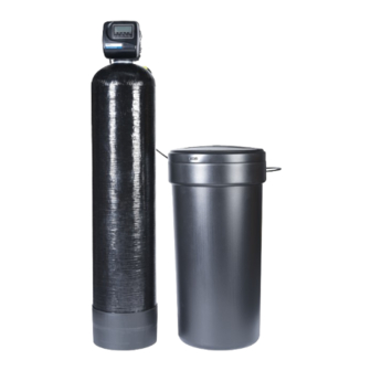
Installation, Operation, and Maintenance Manual
PWDM Water Softening and
Filtration System
Read this Manual BEFORE using this equipment.
Failure to read and follow all safety and use information can
result in death, serious personal injury, property damage, or
damage to the equipment.
Keep this Manual for future reference.
You are required to consult the local building and plumbing
codes prior to installation. If the information in this manual is not
consistent with local building or plumbing codes, the local codes
should be followed. Inquire with governing authorities for additional
local requirements.
Need for Periodic Inspection/Maintenance: This product
must be tested periodically in compliance with local codes, but
at least once per year or more as service conditions warrant.
All products must be retested once maintenance has been
performed. Corrosive water conditions, and/or unauthorized
adjustments or repair could render the product ineffective for the
service intended. Regular checking and cleaning of the product's
internal components helps assure maximum life and proper
product function.
Do not use with water that is microbiologically unsafe or of
unknown quality adequate disinfection before and after the system.
Hydrocarbons such as Kerosene, Benzene, Gasoline, etc., may
damage products that contain O-rings or plastic components.
Exposure to such hydrocarbons may cause the products to leak.
Do not use the product(s) contained in this document on water
supplies that contain Hydrocarbons such as Kerosene, Benzene,
Gasoline, etc.
PWDM Series Dual Media Softening and Filtration System
Contents
System Specification Table . . . . . . . . . . . . . . . . . . . . . . . . . . . . 2
Control Valve Functions . . . . . . . . . . . . . . . . . . . . . . . . . . . . . . . 3
General Installation Guidelines . . . . . . . . . . . . . . . . . . . . . . . . . . 4
General Warnings (continued) . . . . . . . . . . . . . . . . . . . . . . . . . . 5
Pre-Installation Considerations. . . . . . . . . . . . . . . . . . . . . . . . . . 5
Installation Preview . . . . . . . . . . . . . . . . . . . . . . . . . . . . . . . . . . 6
Installation Instructions . . . . . . . . . . . . . . . . . . . . . . . . . . . . . . . 6
Bypass Valve Installation . . . . . . . . . . . . . . . . . . . . . . . . . . . . . . 8
Installation Instructions . . . . . . . . . . . . . . . . . . . . . . . . . . . . . . . 9
Start Up. . . . . . . . . . . . . . . . . . . . . . . . . . . . . . . . . . . . . . . . . . 10
PWDM System Programming . . . . . . . . . . . . . . . . . . . . . . . . . 11
Control Programming . . . . . . . . . . . . . . . . . . . . . . . . . . . . . . . 13
General Operation . . . . . . . . . . . . . . . . . . . . . . . . . . . . . . . . . . 13
Programming (Note) . . . . . . . . . . . . . . . . . . . . . . . . . . . . . . . . 14
System Maintenance . . . . . . . . . . . . . . . . . . . . . . . . . . . . . . . . 14
Control Valve Components Described . . . . . . . . . . . . . . . . . . . 14
Sanitizing the System . . . . . . . . . . . . . . . . . . . . . . . . . . . . . . . 14
Control Valve Components Described (continued) . . . . . . . . . . 15
Drive Cap Assembly . . . . . . . . . . . . . . . . . . . . . . . . . . . . . . . . 15
System Components Described (continued) . . . . . . . . . . . . . . 16
Drawings and Part Numbers . . . . . . . . . . . . . . . . . . . . . . . . . . 17
Troubleshooting . . . . . . . . . . . . . . . . . . . . . . . . . . . . . . . . . . . . 23
NOTES . . . . . . . . . . . . . . . . . . . . . . . . . . . . . . . . . . . . . . . . . . 27
IOM-WQ-PWDM
Advertisement
Table of Contents

Related Manuals for Watts PWDM Series


Summary of Contents for Watts PWDM Series
-
Page 1: Table Of Contents
PWDM Series Dual Media Softening and Filtration System All products must be retested once maintenance has been performed. Corrosive water conditions, and/or unauthorized... -
Page 2: System Specification Table
Total Dissolved Solids Must be below 750mg/l for the softener to produce less than 1 grain per gallon soft water. *For all other guideline information please contact your Watts Representitive NOTES: Input water conditions will influence the performance and flow rate of the system. -
Page 3: Control Valve Functions
Control Valve Functions Control Valve Function and Cycles of Operation This glass filled Noryl fully automatic control valve is designed as the The transformer power pack comes with a 15-foot power cord and is primary control center to direct and regulate all cycles of a water designed for use with the control valve. -
Page 4: General Installation Guidelines
• All electrical connections must be completed according to local codes. If risk of vacuum exists, install Watts # 0556031 vacuum relief • The power outlet must be grounded. valve in the inlet supply line to protect the system against •... -
Page 5: General Warnings (Continued)
125 pounds of water pressure. recommended. Dow Corning Silicone Compound (available from ® Watts), is recommended for best possible results. Dow Corning B. Electrical Facilities ® Release Compound is used in the manufacture of this control valve. -
Page 6: Installation Preview
Installation Preview Conduct a visual check of all equipment for any damage that may have occurred during shipment. Do not exceed water pressure of 125 psi (8.5 bar). Do not exceed 110°F (43.3°C). Do not subject unit to freezing conditions. If there is obvious damage to any equipment, it should be noted on the carrier’s Bill Of Lading. - Page 7 System Components Described...
-
Page 8: Bypass Valve Installation
Bypass Valve Installation When installing sweat copper follow state and federal codes by using a lead free solder and flux. Use a joint compound to seal threaded pipe. Some homes use the cold water pipes for an electrical ground (metal only). When finished with plumbing, a ground/ bonding wire should be connected to the copper pipes to complete the ground circuit. -
Page 9: Installation Instructions
Installation Instructions Move Water Softener Into Place Assembling the Inlet/Oulet Plumbing Adapters 1. Make sure floor is level. Slip the nut onto the fitting first, then the split ring second and the o-ring last. Hand tighten the nut. If the fitting is leaking tightening the nut will not stop the leak. -
Page 10: Start Up
Installation Figure 7: Also be sure drain line has an air gap. Figure 8: Drain Line Connection using Compressions Nut Start Up 8. Allow system to fill with water until water flow is observed at the drain line discharge end. Air will come out of the drain line until the backwashing tank is completely purged of air. -
Page 11: Pwdm System Programming
PWDM System Programming PWDM Quick Programming Guide A quick programming guide has been listed below for convenience specifically for the PWDM Water Softening and Filtration System. For other programming requirements not listed in the Quick Programming Guide, please see the detailed programming section of this manual. The electronics in the PWSR control valve are used across a wide variety of control valves and applications, including backwashing filters. - Page 12 3 - 5 seconds Day Override. Default should be set to 14 Days. Watts Pure Water water softeners regener- Press Next Button ate based on water usage, but this day override setting will come into play if the softener sits idle or has not regenerated and will automatic initiate regeneration on the 14th day.
-
Page 13: Control Programming
Control Programming Installer (I) Displays/Settings STEP 1I – Press NEXT and arrow up simultaneously Press NEXT to go to step 4I. Press REGEN to return to for 3 seconds. previous step. STEP 2I – Hardness: Set the amount of hardness STEP 4I –... -
Page 14: Programming (Note)
Programming (Note) Sanitizing the System Set Time of Day 1. At completion of softener installation you should sanitize The user can also set the time of day. the system. Time of day should only need to be set 2. Take the lid off of the salt after extended power outages or when tank and then take the cap day-light savings time begins or ends. -
Page 15: Control Valve Components Described (Continued)
Control Valve Components Described (continued) Drive Assembly lip seals. The lip seals are red or clear in color and have a special slippery coating so that the piston does not need to be coated or The drive assembly consists of the following parts: lubricated. -
Page 16: System Components Described (Continued)
System Components Described (continued) Plumbing Adapter Assemblies The drain line flow control and fitting are located on top of the control valve and replaceable without the use of special tools. The installation fittings are used to connect the optional bypass or the control to the plumbing system. -
Page 17: Drawings And Part Numbers
Drawings and Part Numbers Brine Tank and Softener Tank 7300167 7300165 Mineral Tank - 68110834 7300224 Figure 17 Figure 18 Front Cover and Drive Assembly DRAWING NO. ORDER NO. DESCRIPTION QTY. 7300839 W100SM Front Cover ASY 7300833 W100SM Motor KC12F3106-01 W100SM Drive Bracket &... - Page 18 Drawings and Part Numbers Drive Cap Assembly, Downflow Piston, Regenerant Piston and Spacer Stack Assembly DRAWING NO. ORDER NO. DESCRIPTION QTY. 7300826 W100SM Spacer Stack Assembly KC12V3004 Drive Cap ASY KC12V3135 O-ring 228 7300832 W100SM Piston Downflow ASY 7300836 W100SM Regenerant Piston KC12V3180 O-ring 337 Note: The regenerant piston is not used in backwash only applications...
- Page 19 Drawings and Part Numbers Brine Line Connection ORDER NO. DESCRIPTION V4144-01 3/8” Quick Connect Fitting 3/8" Quick Connect Fitting Drain Line - 3/4" DRAWING NO. ORDER NO. DESCRIPTION QTY. KC12H4615 Elbow Locking Clip KC12PKP10T58 Polytube insert 5/8 KC12V3192 W100SM Nut 3/4 Drain Elbow KC12V3158-01 W100SM Drain Elbow 3/4 Male ASY KC12V3163...
- Page 20 Drawings and Part Numbers Water Meter ORDER NO. DESCRIPTION 7300827 Water Meter Assembly with Turbine Inlet/Outlet Plumbing Adapters Assemblies ORDER NO. DESCRIPTION ORDER NO. DESCRIPTION 0002169 1" PVC Male NPT Elbow (pair) KC11V3007-01 3/4" & 1" PVC Socket 90 Elbow (pair) ORDER NO.
- Page 21 Drawings and Part Numbers Bypass Valve Assembly ORDER NO. DESCRIPTION 0002167 Bypass Valve Assembly PWSR Wrench (Order No. 7300839) Although no tools are necessary to assemble or disassemble the valve, the PWSR Wrench (shown in various positions on the valve) may be purchased to aid in assemble or disassembly.
- Page 22 Drawings and Part Numbers Flow Diagram...Service Flow Diagram...Rinse Flow Diagram...Backwash Flow Diagram...Fill Flow Diagram...Downflow Brine...
-
Page 23: Troubleshooting
Troubleshooting System Troubleshooting Problem Cause Correction 1. Loss of Resin or GAC Media A. Broken distribution tube A. Replace distribution tube. B. Inlet/Outlet connection reversed. B. Reconnect inlet/outlet connection properly. 2. Softener fails to regenerate. A. Electrical service to unit has A. - Page 24 Troubleshooting System Troubleshooting (continued) Problem Cause Correction 8. Excessive water in brine tank. A. Plugged drain line flow control. A. Clean flow control. B. Plugged injector system. B. Clean injector and screen. C. Foreign material in brine valve. C. Replace timer. D.
- Page 25 Troubleshooting Troubleshooting Programming Problem Possible Cause Solution 1. Timer does not display time of day a. Transformer unplugged a. Connect power b. No electric power at outlet b. Repair outlet or use working outlet c. Defective transformer c. Replace transformer d.
- Page 26 Troubleshooting Troubleshooting Programming (continued) Problem Possible Cause Solution 6. Control valve stalled in regeneration a. Motor not operating a. Replace motor b. No electric power at outlet b. Repair outlet or use working outlet c. Defective transformer c. Replace transformer d.
-
Page 27: Notes
NOTES... - Page 28 LIMITED WARRANTY: Certain Watts products come with a limited warranty from Watts Regulator Co. Other products may have no warranty or are covered by the original manufacturer’s warranty only. For specific product warranty information, please visit www.watts.com or the published literature that comes with your product. Any remedies stated in such warranties are exclusive and are the only remedies for breach of warranty.
Need help?
Do you have a question about the PWDM Series and is the answer not in the manual?
Questions and answers