Table of Contents
Advertisement
Quick Links
Installation, Operation, and Maintenance Manual
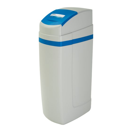
PWSCAB Series
Residential Cabinet Water Softener
Read this Manual BEFORE using this equipment.
Failure to read and follow all safety and use information
can result in death, serious personal injury, property
damage, or damage to the equipment.
Keep this Manual for future reference.
You are required to consult the local building and plumbing
codes prior to installation. If the information in this manual
is not consistent with local building or plumbing codes,
the local codes should be followed. Inquire with governing
authorities for additional local requirements.
Need for Periodic Inspection/Maintenance: This product
must be tested periodically in compliance with local codes, but
at least once per year or more as service conditions warrant. All
products must be retested once maintenance has been performed.
Corrosive water conditions, and/or unauthorized adjustments or
repair could render the product ineffective for the service intended.
Regular checking and cleaning of the product's internal components
helps assure maximum life and proper product function.
Do not use with water that is microbiologically unsafe or of unknown
quality. Adequate disinfection required before and after the system.
Hydrocarbons such as Kerosene, Benzene, and Gasoline may
damage products that contain O-rings or plastic components.
Exposure to such hydrocarbons may cause the products to
leak. Do not use the product(s) contained in this document on
water supplies that contain Hydrocarbons such as Kerosene,
Benzene, Gasoline, and others.
Watts is not responsible failure of product due to connectivity
issues, power issues, or improper installation.
PWSCAB Series Softener
Contents
System Specification . . . . . . . . . . . . . . . . . . . . . . . . . . . . . . . . . . . . . . . 2
System Dimensions . . . . . . . . . . . . . . . . . . . . . . . . . . . . . . . . . . . . . . . . 2
Control Valve Functions and Operation Cycles. . . . . . . . . . . . . . . . . . . . 3
General Installation Guidelines . . . . . . . . . . . . . . . . . . . . . . . . . . . . . . . . 4
Installation Preview . . . . . . . . . . . . . . . . . . . . . . . . . . . . . . . . . . . . . . . . 5
Preinstallation Considerations . . . . . . . . . . . . . . . . . . . . . . . . . . . . . . . . 6
Installation Instructions . . . . . . . . . . . . . . . . . . . . . . . . . . . . . . . . . . . . . 6
System Programming . . . . . . . . . . . . . . . . . . . . . . . . . . . . . . . . . . . . . 10
Control Programming . . . . . . . . . . . . . . . . . . . . . . . . . . . . . . . . . . . . . 12
General Operation . . . . . . . . . . . . . . . . . . . . . . . . . . . . . . . . . . . . . . . . 13
Clock Programming. . . . . . . . . . . . . . . . . . . . . . . . . . . . . . . . . . . . . . . 14
Sanitizing the System . . . . . . . . . . . . . . . . . . . . . . . . . . . . . . . . . . . . . 14
System Components. . . . . . . . . . . . . . . . . . . . . . . . . . . . . . . . . . . . . . 15
Drawings and Part Numbers . . . . . . . . . . . . . . . . . . . . . . . . . . . . . . . . 18
Troubleshooting . . . . . . . . . . . . . . . . . . . . . . . . . . . . . . . . . . . . . . . . . . 24
IOM-WQ-PWSCAB
Advertisement
Table of Contents

Related Manuals for Watts PWSCAB Series


Summary of Contents for Watts PWSCAB Series
-
Page 1: Table Of Contents
Control Programming ........12 Watts is not responsible failure of product due to connectivity General Operation . -
Page 2: System Specification
System Specification Call customer service if you need assistance with technical details. MINERAL TANK FLOW RATE & PRESSURE ORDERING CAPACITY PIPE SIZE TANK RESIN GRAVEL CABINET SIZE SALT FILL SERVICE DROP SHIP WT. MODEL NO. CODE (MAX.) (IN.) SIZE (LB) (W x D x H) (LB) (GPM) -
Page 3: Control Valve Functions And Operation Cycles
Control Valve Functions and Operation Cycles This glass-filled Noryl fully automatic control valve is designed as The transformer power pack comes with a 15-foot power cord and ® the primary control center to direct and regulate all cycles of a water is designed for use with the control valve. -
Page 4: General Installation Guidelines
IMPORTANT SAFEGUARDS General Installation Guidelines Electrical This water softener's control valve conforms to UL/CE Standards. Generic valves were tested and certified for compliance as verified by the agency listing. This water softening system is to be used only for potable water. Inspect As with any electrical product, care should be taken to guard the water softening system for carrier shortage or shipping against the potential risk of fire, electric shock, and injury to... -
Page 5: Installation Preview
Installation Preview IMPORTANT SAFEGUARDS Conduct a visual check of all equipment for any damage that may have occurred during shipment. Control Valve If there is obvious damage to any equipment, it should be noted on • This glass-filled Noryl (or equivalent) fully automatic control valve the carrier’s Bill Of Lading. -
Page 6: Preinstallation Considerations
Preinstallation Considerations Installation Instructions 1. Turn off water heater(s). Water Pressure 2. Turn off the main water supply to the home and open an inside A minimum of 25 pounds of water pressure is required for faucet (cold and hot) to relieve any pressure within the plumbing regeneration valve to operate effectively. - Page 7 Move Water Softener Into Place Slip the nut onto the fitting first, next the split ring, and then the O-ring. Hand tighten the nut. If the fitting is leaking, tightening the 1. Connect the cold water supply to the inlet of the water softening nut does not stop the leak.
- Page 8 Bypass Valve Installation Figure 2 Plumbing with 3-Way Bypass Figure 1 Plumbing with Standard Bypass Figure 3 Bypass (standard) Figure 4 3-Way Bypass Plumbing When installing sweat copper follow state and federal codes by using a lead-free solder and flux. Use a joint compound to seal threaded pipe.
- Page 9 Figure 7 Required Air Gap for Drain Line Figure 8 Drain Line Connection Start Up 8. Air comes out of the drain line until the backwashing tank is completely purged of air. Then water flows to drain. Allow water 1. Place the bypass valve in the Bypass position or mode. (See to flow to drain for 15 minutes or until the water to drain is clear Figures 9, 10, and 11.) of resin color throw.
-
Page 10: System Programming
System Programming A quick programming guide has been included for convenience, specifically for the PWSCAB series water softening system. (See Charts 1, 2, and 3.) For other programming requirements not listed, see the detailed programming sections that follow. The electronics in the PWSCAB control valve are used across a wide variety of control valves and applications, including backwashing filters. - Page 11 Example: 18 grains per gallon (GPG). Adjust grains per gallon with the UP and DOWN arrows. simultaneously for 3 to 5 seconds Day Override. Default should be set to 14 Days. Watts Pure Water water softeners regenerate Press NEXT based on water usage, but this day override setting comes into play if the softener sits idle or has not regenerated.
-
Page 12: Control Programming
Control Programming CONTROL PROGRAMMING Installer (I) Displays/Settings INSTALLER (I) Displays/Settings STEP 1I – Press NEXT and UP arrow simultaneously STEP 4I – Next Regeneration Time (hour): Set the Press NEXT to go to step 4I. Press REGEN to for 3 seconds. hour of day for regeneration using the DOWN or UP return to previous step. -
Page 13: General Operation
will be called for on that day even if sufficient the hour of day for regeneration using down or up STEP 4I – Next Regeneration Time (hour): Set usly for 3 seconds. STEP 2I – Hardness: Set the amount of hard- number of gallons were not used to call for arrow buttons. -
Page 14: Clock Programming
Clock Programming Sanitizing the System PROGRAMMING (NOTE) SANITIZING THE SYSTEM 1. At completion of softener installation, sanitize the system. Set Time of Day SET TIME OF DAY 1. At completion of softener 2. Remove the Upper Cabinet Assembly from the salt tank and then Time of day should only need to be set installation you should take the cap off of the brine well. -
Page 15: System Components
System Components Components Drive Cap Assembly with Main Piston and Regenerant Piston The control valve consists of the following components: • Drive Assembly The drive gears turn the main gear of the drive cap assembly, which moves the piston. The screw-driven, horizontally moving piston •... - Page 16 Water Meter or Meter Plug Table 1 Injector Order Information The water meter is installed on the outlet side of the control valve. Part Number Color Tank Diameter The water meter uses a turbine to total gallons of treated water. The KC11V3010-1D 9"...
- Page 17 Bypass Valve The bypass valve is typically used to isolate the control valve from the plumbing system’s water pressure in order to perform control valve repairs or maintenance. The W100SM bypass valve is particularly unique in the water treatment industry due to its versatility and state-of-the-art design features.
-
Page 18: Drawings And Part Numbers
Drawings and Part Numbers Figure 17 Figure 18 Front Cover and Drive Assembly DRAWING NO. ORDER NO. DESCRIPTION QTY. 7300839 W100SM Front Cover ASY 7300833 W100SM Motor FRONT COVER AND DRIVE ASSEMBLY KC12F3106-01 W100SM Drive Bracket & Spring Clip Drawing No. Order No. - Page 19 DRAWINGS AND PART NUMBERS DRAWINGS AND PART NUMBERS Drive Cap Assembly, Downflow Piston, Upflow Piston, Regenerant Piston, and Spacer Stack Assembly DRIVE CAP ASSEMBLY, DOWNFLOW PISTON, UPFLOW PISTON, DRIVE CAP ASSEMBLY, DOWNFLOW PISTON, UPFLOW PISTON, REGENERANT PISTON AND SPACER STACK ASSEMBLY DRAWING NO.
- Page 20 DRAWINGS AND PART NUMBERS Brine Line Connection Drawing No. Order No. Description Qty. KC12V3195-01 W100SM Refill Port Plug ASY KC12H4615 Elbow Locking Clip ORDER NO. DESCRIPTION KC12JCP-P-6 Polytube insert 3/8 V4144-01 3/8" Quick Connect Fitting KC12JCPG-6PBLK Nut 3/8 KC12H4613 Elbow Cap 3/8 KC12V3163 O-ring 019 KC12V3165-01...
- Page 21 Water Meter and Meter Plug ORDER NO. DESCRIPTION 7300827 Water Meter Plug Assembly Installation Fitting Assemblies ORDER NO. DESCRIPTION ORDER NO. DESCRIPTION 0002169 1" PVC Male NPT Elbow (pair) KC11V3007-01 3/4" & 1" PVC Socket 90 Elbow (pair) ORDER NO. DESCRIPTION ORDER NO.
- Page 22 Bypass Valve Assembly ORDER NO. DESCRIPTION 0002167 Bypass Valve Assembly Wrench (Order No. 7300839) Although no tools are necessary to assemble or disassemble the valve, the wrench (shown in various positions on the valve) may be purchased to aid in assembly or disassembly.
- Page 23 DRAWINGS AND PART NUMBERS flow diagram...service flow diagram...rinse Flow Diagram...Service Flow Diagram...Rinse Flow Diagram...Backwash Flow Diagram...Fill flow diagram...backwash flow diagram...fill Flow Diagram...Downflow Brine flow diagram...downflow brine...
-
Page 24: Troubleshooting
Troubleshooting System Troubleshooting Problem Cause Correction Loss of resin. Broken distribution tube. Replace distribution tube. Inlet/Outlet connection reversed. Reconnect inlet/outlet connection properly. Softener fails to regenerate. Electrical service to unit has Assure permanent electrical service been interrupted. (check fuse, plug, pull chain, or switch). Timer is defective. - Page 25 System Troubleshooting, cont. Problem Cause Correction Excessive water in brine tank. Plugged drain line flow control. Clean flow control. Plugged injector system. Clean injector and screen. Foreign material in brine valve. Replace timer. Defective controller. Replace controller. Foreign material in brine Clean brine line flow control.
- Page 26 Programming Troubleshooting Problem Possible Cause Solution Timer does not display time of day. Transformer unplugged. Connect power. No electric power at outlet. Repair outlet or use working outlet. Defective transformer. Replace transformer. Defective PC board. Replace PC board. Timer does not display Switched outlet.
- Page 27 Programming Troubleshooting, cont. Problem Possible Cause Solution Control valve stalled in regeneration. Motor not operating. Replace motor. No electric power at outlet. Repair outlet or use working outlet. Defective transformer. Replace transformer. Defective PC board. Replace PC board. Broken drive gear or drive cap assembly. Replace drive gear or drive cap assembly.
- Page 28 LIMITED WARRANTY: Certain Watts Pure Water products come with a limited warranty from Watts Regulator Co. Other products may have no warranty or are covered by the original manufacturer’s warranty only. For specific product warranty information, please visit www.watts.com or the published literature that comes with your product. Any remedies stated in such warranties are exclusive and are the only remedies for breach of warranty.
Need help?
Do you have a question about the PWSCAB Series and is the answer not in the manual?
Questions and answers