lancer IBD44 Series Operation Manual

lancer IBD44 Series Operation Manual

Ice beverage dispensers
Table of Contents

Advertisement

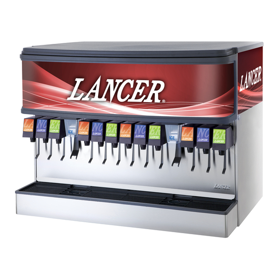
ICE BEVERAGE DISPENSERS, IBD44 SERIES 4500
Operation Manual
PN: 28-0420/02
Lancer Corp.
6655 Lancer Blvd.
San Antonio, Texas 78219
800-729-1500
Technical Support/Warranty: 800-729-1550
custserv@lancercorp.com
lancercorp.com
Manual PN: 28-0420/02
FEBRUARY 2006
Model Number
FOR QUALIFIED INSTALLER ONLY
"Lancer" is the registered trademark of Lancer © 2013 by Lancer, all rights reserved.

Advertisement

Table of Contents
loading
Need help?

Need help?

Do you have a question about the IBD44 Series and is the answer not in the manual?

Questions and answers

Subscribe to Our Youtube Channel

Summary of Contents for lancer IBD44 Series

  • Page 1 Lancer Corp. 6655 Lancer Blvd. San Antonio, Texas 78219 800-729-1500 Technical Support/Warranty: 800-729-1550 custserv@lancercorp.com lancercorp.com Manual PN: 28-0420/02 FEBRUARY 2006 Model Number FOR QUALIFIED INSTALLER ONLY “Lancer” is the registered trademark of Lancer © 2013 by Lancer, all rights reserved.
  • Page 2: Table Of Contents

    ABOUT THIS MANUAL This booklet is an integral and essential part of the product and should be handed over to the operator after the installation and preserved for any further consultation that may be necessary. Please read carefully the guidelines and warnings contained herein as they are intended to provide the user with essential information for the continued safe use and maintenance of the product.
  • Page 3 3.22 BIB PUMP OPERATING, BUT NO FLOW................19 3.23 BIB PUMP CONTINUES TO OPERATE WHEN BAG IS EMPTY........19 3.24 BIB PUMP FAILS TO RESTART AFTER BAG REPLACEMENT........19 3.25 BIB PUMP FAILS TO STOP WHEN DISPENSING VALVE IS CLOSED......19 3.26 LOW OR NO CARBONATION....................19 4.
  • Page 4: Specifications

    IBD - 25” SPECIFICATIONS DIMENSIONS WEIGHT PLAIN WATER SUPPLY Width: 44 in (1118 mm) Shipping: 460 lbs (129.3 kg) Min flowing pressure: Depth: 30.5 in (774.7 mm) Empty: 400 lbs (113.4 kg) 25 PSI (0.172 MPA) Height: 34 in (863.6 mm) Max flowing pressure: 50 PSI (0.345 MPA) SPACE REQUIRED...
  • Page 5: Pre-Intallation Checklist

    PRE-INSTALLATION CHECKLIST TOOLS REQUIRED Oetiker Pliers Slotted Screwdriver Tubing Cutters Phillips Screwdriver Wrench Cordless Drill ACCESSORIES CO2 Regulator Set CO2 Supply Beverage Tubing Oetiker Clamps/Fittings Water Booster Water Regulator BIB SYSTEM BIB Rack BIB Regulator Set BIB Syrup Boxes BIB Connectors - ensure you have the correct connectors for syrup lineup. CONSIDER LOCATION OF THE FOLLOWING PRIOR TO INSTALL Water supply lines Drain...
  • Page 6: Warnings/Cautions

    WARNING/ADVERTENCIA/AVERTISSEMENT The dispenser is for indoor use only. This unit is not a toy. Children should not be supervised not to play with appliance. It should not be used by children or infirm persons without supervision. This appliance is not intended for use by persons (including children) with reduced physical, sensory or mental capabilities, or lack of experience and knowledge, unless they have been given supervision or instruction concerning use of the appliance by a person re- sponsible for their safety.
  • Page 7 Brix. REGLES DE SECURITE POUR L’NSTALLATION DU DISTRIBUTEUR DE SODAS La proprètè da cet ensamable est assurè à I’usine sulvant les spècifications èmis par Lancer . Il est essentiel de respecter les 6 points suivants pour l’installation de l’appareil: 1.
  • Page 8 ELECTRICAL WARNING/ADVERTENCIA ELÉCTRICA/ AVERTISSEMENT ÉLECTRIQUE Check the dispenser serial number plate for correct electrical requirements of unit. Do not plug into a wall electrical outlet unless the current shown on the serial number plate agrees with local current available. Follow all local electrical codes when making connections.
  • Page 9 AUTOMATIC AGITATION/AGITACIÓN AUTOMÁTICA/ Units are equipped with an automatic agitation system and will activate unexpectedly. Do not place hands or for- eign objects in the water bath tank. Unplug the dispenser during servicing, cleaning, and sanitizing. To avoid personal injury, do not attempt to lift the dispenser without assistance. For heavier dispensers, use a mechanical lift. Las unidades están equipadas con un sistema automático de agitación, por lo que se pueden activar repentina- mente.
  • Page 10: Installation

    1. INSTALLATION RECEIVING Each unit is completely tested under operating conditions and thoroughly inspected before shipment. At time of shipment the carrier accepts the unit, and any claim for damage must be made with the carrier. Upon receiving units from the delivering carrier, carefully inspect carton for visible indication of damage.
  • Page 11: Selecting A Location

    M. Finish filling unit with ice. N. Install Top Cover. NOTE: Lancer does not recommend the use of shaved, flake, nugget, or pellet ice in dispensers not properly equipped to do so. O. Set brix ratio for beverage dispensing valves according to manufacturer’s instructions.
  • Page 12: Cleaning And Sanitizing Instructions

    2. CLEANING AND SANITIZING INSTRUCTIONS GENERAL INFORMATION A. Lancer equipment (new or reconditioned) is shipped from the factory cleaned and sanitized in accordance with NSF guidelines. This equipment must be cleaned and sanitized after installation is complete, and the operator of the equipment must provide continuous maintenance as required by this manual and/or state and local health department guidelines to ensure proper operation and sanitation requirements are maintained.
  • Page 13: Ice Bin Cleaning - Startup And Monthly

    L. Wearing sanitary gloves, reassemble all removable parts. M. Fill Unit with ice and replace Top Cover. NOTE: Lancer does not recommend the use of shaved, flake, nugget, or pellet ice in dispensers not properly equipped to do so. N. Reconnect Dispenser to power source.
  • Page 14: Cleaning And Sanitizing Beverage Components Bag-In-Box Systems

    CLEANING AND SANITIZING BEVERAGE COMPONENTS - FIGAL SYSTEMS (CONTINUED) M. Activate valve and draw sanitizing solution through line for a minimum of 60 seconds. This will ensure line is flushed and filled with sanitizing solution. Allow line to stand for at least 30 minutes.
  • Page 15: Troubleshooting

    3. TROUBLESHOOTING ISSUE CAUSE SOLUTION 3.1 No product when switch is activated A. Malfunctioning switch assembly. A. Replace switch assembly. (switch panel is not lit). B. No power to dispenser. B. Check internal breaker and incoming power. C. Malfunctioning power supply. C.
  • Page 16: Water In Ice Bin

    ISSUE CAUSE SOLUTION 3.7 Water in ice bin. A. Coldplate drain is obstructed. A. Remove splash plate and drip tray to obtain access to drain tubes and clear accordingly. 3.8 Water leakage around nozzle. A. Damaged or improperly installed o-ring A.
  • Page 17: Insufficient Syrup Flow

    ISSUE CAUSE SOLUTION 3.14 Insufficient syrup flow. A. Insufficient CO2 pressure to BIB A. Adjust CO2 pressure to BIB pumps to pumps. 80 PSI (min. 70 PSI). Do not exceed manufacturer’s recommendations. B. Shutoff on mounting block not fully B. Open shutoff fully. open.
  • Page 18: Syrup Only Dispensed. No Water, But Co2 Gas Dispensed With Syrup

    ISSUE CAUSE SOLUTION 3.18 Syrup only dispensed. No water, but A. Improper water flow to dispenser. A. Check for water flow to dispenser. CO2 gas dispensed with syrup. B. Carbonator pump motor has timed out B. Reset by turning the unit OFF, then ON (display message on the LCD screen).
  • Page 19: Bib Pump Does Not Operate When Dispensing Valve Is Opened

    ISSUE CAUSE SOLUTION 3.21 BIB pump does not operate when A. Out of CO2, CO2 not turned on, or low A. Replace CO2 supply, turn on CO2 dispensing valve is opened. CO2 pressure. supply, or adjust CO2 pressure to 70-80 PSI. B.
  • Page 20: Light Emitting Diodes (Leds)

    4. LIGHT EMITTING DIODES (LEDS) LED D3 This light is on when the ice dispense switch is activated. If the chute is depressed and the light does not turn on, check to see if the wire harness is connected or if the dispense switch is defective.
  • Page 21 5. AUTOMATIC AGITATION AND LOW ICE ALARM CONTROL (CONTINUED) DIP#1 This switch controls the low ice indicator light. With the switch in the ON position, the light operates when a low ice condition exists. In the OFF position, the light is turned off. The unit is shipped with the light switch in the ON position.
  • Page 22: Illustrations And Parts Listings

    6. ILLUSTRATIONS, PARTS LISTINGS, AND WIRING DIAGRAMS DECALS AND LABELS...
  • Page 23 DECALS AND LABELS (CONTINUED) Item Part No. Description 06-1183 Label, Cleaning, Hopper, IBD 06-1184/01 Label, Cleaning, Merchandiser, IBD 06-2098/01 Label, Plumbing Diagram, IBD44 06-2099/03 Label, Wiring Diagram, IBD44 06-1207 Label, Cold Plate Cleaning, IBD 06-1522 Label, Low Ice, IBD 06-1139 Label, Warning, Lid, IBD 06-1457/01 Panel, Graphics, Coca-Cola, IBD44...
  • Page 24: Final Assembly, Post-Mix Ibd And Ice Dispenser

    FINAL ASSEMBLY, POST-MIX IBD AND ICE DISPENSER...
  • Page 25 FINAL ASSEMBLY, POST-MIX IBD AND ICE DISPENSER (CONTINUED) Item Part No. Description 05-1311/01 Wheel Shroud, IBD44 82-3650 Dispenser, Wheel Assy, Right Side, IBD44 23-1373 Agitator Assy, HEX, IBD 10-0762 Pin, Agitator, HEX, IBD 03-0368 Retainer, RUE-14-S 82-3556 Dispenser Wheel Assy, Left Side, HEX, IBD 05-1392 Lid, One Piece, 44 Inch IBD 82-1980/02...
  • Page 26: Faucet Plate And Ice Chute Sub-Assembly, Post-Mix

    FAUCET PLATE AND ICE CHUTE SUB-ASSEMBLY, POST-MIX TIE WRAP TIE WRAP TO TRANSFORMER TO KEYSWITCH TIE WRAP TIE WRAP TIE WRAP...
  • Page 27 FAUCET PLATE AND ICE CHUTE SUB-ASSEMBLY, POST-MIX (CONTINUED) Item Part No. Description Item Part No. Description 82-2260 Faucet Plate Assy, 12 Valve, R 11 82-1899 Trim Assy, IBD44 IBD44 R 12 30-6678 Cover, Electric Box, IBD44 04-0308 Screw, 10 - 32 x 0.438, PHD R 13 04-0477 Screw, 8 - 32 x 0.375, PHD...
  • Page 28: Electrical Box And Gear Motor Sub-Assembly, Post-Mix

    ELECTRICAL BOX AND GEAR MOTOR SUB-ASSEMBLY, POST-MIX FROM BLUE LEADS ON BALLAST TO YELLOW LEADS ON BALLAST FROM RED LEADS ON BALLAST 28 29...
  • Page 29 ELECTRICAL BOX AND GEAR MOTOR SUB-ASSEMBLY, POST-MIX (CONTINUED) Item Part No. Description 82-2315 Foamed Tank Assy, IBD44 02-0406 Seal, Shaft, Motor, IBD 05-1589 Body, Detector, Sensor, Plug 06-2488 Label, Ice Link Tag, IBD 52-2450 Harness Assy, Detector, IBD 52-2353 Body Assy, Detector, Sensor 52-2352 Body Assy, Emitter, Sensor 02-0155...
  • Page 30: Wiring Diagram - 115V/60Hz

    WIRING DIAGRAM - 115V/60HZ...
  • Page 31: Agitation - Controls, Expanded View

    AGITATION - CONTROLS, EXPANDED VIEW 7. DISPENSER DISPOSAL   To prevent possible harm to the environment from improper disposal, recycle the unit by locating an authorized recycler or contact the retailer where the product was pur chased. Comply with local regulations regarding disposal of the refrigerant and insulation.
  • Page 32 Lancer Corp. 800-729-1500 Technical Support/Warranty: 800-729-1550 custserv@lancercorp.com lancercorp.com...

This manual is also suitable for:

Ibd 4500-44

Table of Contents