
Subscribe to Our Youtube Channel
Related Manuals for Eaton Power Xpert 9395 UPS


Summary of Contents for Eaton Power Xpert 9395 UPS
- Page 1 Power Xpert 9395 UPS, Plus 1 UPS, and 825/550 UPS ™ 450–825 kVA Installation and Operation Manual For use with Two UPM (450–550 kVA), Three UPM (650–825 kVA), and Plus 1 (650–825 kVA) UPS Models...
- Page 3 Power Xpert 9395 UPS, Plus 1 UPS, and 825/550 UPS ™ 450–825 kVA Installation and Operation Manual For use with Two UPM (450–550 kVA), Three UPM (650–825 kVA), and Plus 1 (650–825 kVA) UPS Models...
- Page 4 Protection Association, Inc. All other trademarks are property of their respective companies. Copyright 2010-2018 Eaton Corporation, Raleigh, NC, USA. All rights reserved. No part of this document may be reproduced in any way without the express written approval of Eaton Corporation.
-
Page 5: Table Of Contents
Distributed Bypass Tie Cabinet Installation..........4-19 Power Xpert 9395 UPS (450–825 kVA) Installation and Operation Manual 164201725—Rev 10 www.eaton.com/powerquality... - Page 6 Using the Menu..............Power Xpert 9395 UPS (450–825 kVA) Installation and Operation Manual 164201725—Rev 10 www.eaton.com/powerquality...
- Page 7 7.4.16 Starting a Single UPM ............. 7-34 Power Xpert 9395 UPS (450–825 kVA) Installation and Operation Manual 164201725—Rev 10 www.eaton.com/powerquality...
- Page 8 Performing Preventive Maintenance............Power Xpert 9395 UPS (450–825 kVA) Installation and Operation Manual 164201725—Rev 10 www.eaton.com/powerquality...
- Page 9 WARRANTY....................Power Xpert 9395 UPS (450–825 kVA) Installation and Operation Manual 164201725—Rev 10 www.eaton.com/powerquality...
- Page 10 This page intentionally left blank. Power Xpert 9395 UPS (450–825 kVA) Installation and Operation Manual 164201725—Rev 10 www.eaton.com/powerquality...
- Page 11 Figure 4-26. Typical Alarm Relay Connection ............4-33 Power Xpert 9395 UPS (450–825 kVA) Installation and Operation Manual 164201725—Rev 10 www.eaton.com/powerquality...
- Page 12 Continuous Static Switch ................6-22 viii Power Xpert 9395 UPS (450–825 kVA) Installation and Operation Manual 164201725—Rev 10 www.eaton.com/powerquality...
- Page 13 Figure 7-33. System Status Screen..............7-60 Power Xpert 9395 UPS (450–825 kVA) Installation and Operation Manual 164201725—Rev 10 www.eaton.com/powerquality...
- Page 14 Figure 9-4. FI-UPM Air Filter Location..............Power Xpert 9395 UPS (450–825 kVA) Installation and Operation Manual 164201725—Rev 10 www.eaton.com/powerquality...
-
Page 15: Introduction
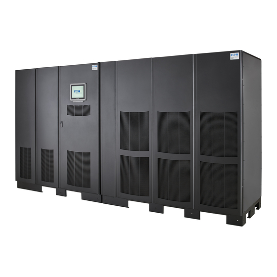
The Power Xpert 9395 UPS continually monitors incoming electrical power and removes the surges, spikes, sags, and other irregularities that are inherent in commercial utility power. Working with a building's electrical system, the UPS system supplies clean, consistent power that sensitive electronic equipment requires for reliable operation. -
Page 16: Figure 1-1. Power Xpert 9395 Three Upm Ups (650-825 Kva)
Older LCD Pushbutton Control Panel ISBM or IOM SECTION UPM SECTION FI-UPM Figure 1-2. Power Xpert 9395 Plus 1 UPS (650–825 kVA) with the Field Installed UPM Power Xpert 9395 UPS (450–825 kVA) Installation and Operation Manual 164201725—Rev 10 www.eaton.com/powerquality... -
Page 17: Figure 1-3. Power Xpert 9395-825/550 Two Upm Ups (450-550 Kva)
Figure 1-3. Power Xpert 9395-825/550 Two UPM UPS (450–550 kVA) Color Touchscreen Control Panel ISBM or IOM SECTION UPM SECTION Figure 1-4. Power Xpert 9395-825/550 Two UPM UPS with the Field Installed UPM (450–825 kVA) Power Xpert 9395 UPS (450–825 kVA) Installation and Operation Manual 164201725—Rev 10 www.eaton.com/powerquality... -
Page 18: Ups Standard Features
1.2.1 Integrated Battery Cabinets Battery backup protection can be provided by equipping the UPS system with up to four Eaton 9395 battery cabinets containing sealed lead–acid, maintenance–free batteries. The battery cabinets are available with a 240-cell configuration. The cabinets are designed for standalone installation and may be installed adjacent to the UPS or in a separate location. -
Page 19: Sync Control
1.2.9 Inherent Redundancy To deliver greater reliability, the Power Xpert 9395 UPS can be configured by an authorized Eaton Customer Service Engineer for inherent redundancy if a FI-UPM is installed. When configured, the UPS automatically becomes redundant if the load is at or below the capacity of the UPMs minus the capacity of one UPM. Under normal conditions the UPMs in the UPS share the load equally. -
Page 20: Energy Saver System And High Alert Modes
In High Alert mode, all idle UPMs go online for one hour. At the completion of the hour, the UPS defaults back to VMMS mode. If the High Alert command is received during the one hour, the one hour timer will be restarted. Power Xpert 9395 UPS (450–825 kVA) Installation and Operation Manual 164201725—Rev 10 www.eaton.com/powerquality... -
Page 21: Monitoring And Communication
Using This Manual This manual describes how to install and operate the Power Xpert 9395 UPS (450–550 kVA) cabinet. Read and understand the procedures described in this manual to ensure trouble-free installation and operation. In particular, be thoroughly familiar with the REPO procedure (see paragraph 7.3.25 on page 7-26). -
Page 22: Conventions Used In This Manual
In this manual, the term UPS refers only to the UPS cabinet and its internal elements. The term UPS system refers to the entire power protection system – the UPS cabinet, the battery cabinet, and options or accessories installed. Power Xpert 9395 UPS (450–825 kVA) Installation and Operation Manual 164201725—Rev 10 www.eaton.com/powerquality... -
Page 23: Symbols, Controls, And Indicators
This symbol indicates that you should not discard waste electrical or electronic equipment (WEEE) in the trash. For proper disposal, contact your local recycling/reuse or hazardous waste center. Power Xpert 9395 UPS (450–825 kVA) Installation and Operation Manual 164201725—Rev 10 www.eaton.com/powerquality... -
Page 24: For More Information
Detailed illustrations of the cabinet, including dimension and connection point drawings. Refer to the Eaton 9390 and 9395 Sync Control Installation and Operation Manual for the following additional information: Installation instructions, including site preparation, planning for installation, and wiring and safety information. -
Page 25: Safety Warnings
Do not install or operate the UPS system close to gas or electric heat sources. The operating environment should be maintained within the parameters stated in this manual. Keep surroundings uncluttered, clean, and free from excess moisture. Power Xpert 9395 UPS (450–825 kVA) Installation and Operation Manual 164201725—Rev 10 www.eaton.com/powerquality... - Page 26 Une mise au rebut réglementaire des batteries est obligatoire. Consulter les règlements en vigueur dans votre localité. Ne jamais jeter les batteries au feu. L'exposition aux flammes risque de les faire exploser. Power Xpert 9395 UPS (450–825 kVA) Installation and Operation Manual 164201725—Rev 10 www.eaton.com/powerquality...
- Page 27 Installation...
-
Page 29: Ups Installation Plan And Unpacking
If the UPS is to be operated at an altitude higher than 1000m (3000 ft), contact an Eaton service representative for important information about high altitude operation. The operating environment must meet the weight, clearance, and environmental requirements specified. -
Page 30: Installation Considerations
Figure 3-1 through Figure 3-14. Dimensions are in millimeters (inches). Table 3-1 does not include the weight of the Field Installed UPM (FI-UPM). For Field Installed UPM (FI-UPM) weights and dimensions, refer to the Eaton 9395 Field Installed UPM Mechanical Installation Manual, listed in paragraph 1.7. - Page 31 UPS Installation Plan and Unpacking CAUTION If Eaton battery cabinets are located in the same room as the UPS, the battery cabinet environmental requirements supercede the UPS requirements. Operating temperatures above the recommended range will result in decreased battery life and performance, and will reduce or void the battery warranty.
-
Page 32: Figure 3-1. Ups Cabinet Dimensions - Three Upm (Front View)
Dimensions are in millimeters [inches]. Figure 3-1. UPS Cabinet Dimensions - Three UPM (Front View) Dimensions are in millimeters [inches]. Figure 3-2. UPS Cabinet Dimensions – Two UPM (Front View) Power Xpert 9395 UPS (450–825 kVA) Installation and Operation Manual 164201725—Rev 10 www.eaton.com/powerquality... -
Page 33: Figure 3-3. Ups Cabinet Dimensions (Right Side View)
871.7 [34.3] Dimensions are in millimeters [inches]. Figure 3-3. UPS Cabinet Dimensions (Right Side View) Dimensions are in millimeters [inches]. Figure 3-4. ISBM Section Dimensions (Front View) Power Xpert 9395 UPS (450–825 kVA) Installation and Operation Manual 164201725—Rev 10 www.eaton.com/powerquality... -
Page 34: Figure 3-5. Upm Section Dimensions - Three Upm (Front View)
Dimensions are in millimeters [inches]. Figure 3-5. UPM Section Dimensions – Three UPM (Front View) Dimensions are in millimeters [inches]. Figure 3-6. UPM Section Dimensions – Two UPM (Front View) Power Xpert 9395 UPS (450–825 kVA) Installation and Operation Manual 164201725—Rev 10 www.eaton.com/powerquality... -
Page 35: Figure 3-7. Isbm Section Dimensions (Top View)
UPS Installation Plan and Unpacking Front Dimensions are in millimeters [inches]. Figure 3-7. ISBM Section Dimensions (Top View) Front Dimensions are in millimeters [inches]. Figure 3-8. ISBM Section Dimensions (Bottom View) Power Xpert 9395 UPS (450–825 kVA) Installation and Operation Manual 164201725—Rev 10 www.eaton.com/powerquality... -
Page 36: Figure 3-9. Upm Section Dimensions - Three Upm (Top View)
Dimensions are in millimeters [inches]. Figure 3-9. UPM Section Dimensions – Three UPM (Top View) Front Dimensions are in millimeters [inches]. Figure 3-10. UPM Section Dimensions – Two UPM (Top View) Power Xpert 9395 UPS (450–825 kVA) Installation and Operation Manual 164201725—Rev 10 www.eaton.com/powerquality... -
Page 37: Figure 3-11. Isbm Section Center Of Gravity - Continuous Static Switch
Dimensions are in millimeters [inches]. Figure 3-11. ISBM Section Center of Gravity – Continuous Static Switch Dimensions are in millimeters [inches]. Figure 3-12. UPM Section Center of Gravity – Three UPM Power Xpert 9395 UPS (450–825 kVA) Installation and Operation Manual 164201725—Rev 10 www.eaton.com/powerquality... -
Page 38: Figure 3-13. Upm Section Center Of Gravity - Two Upm
(Square) 1.57 [0.40] Needed to remove key Front View 1/2” Knockout Pattern (Typical 5 Sides) Dimensions are in millimeters [inches]. Figure 3-14. Remote EPO Switch Dimensions 3-10 Power Xpert 9395 UPS (450–825 kVA) Installation and Operation Manual 164201725—Rev 10 www.eaton.com/powerquality... -
Page 39: Ups System Power Wiring Preparation
CANNOT be used. DO NOT bond the inverter center point (E12) to ground: this is an internal UPS function and requires no additional work by the installer or user. Please contact the Eaton help desk listed in Chapter 1 for additional guidance regarding dual high impedance ground sources. - Page 40 Because of the future upgradability to a fully rated 825 kVA UPS with the addition of the FI-UPM, the UPS wiring is specified for 825 kVA in Table 3-6 and Table 3-7. Wire sizes listed are for copper wiring only. 3-12 Power Xpert 9395 UPS (450–825 kVA) Installation and Operation Manual 164201725—Rev 10 www.eaton.com/powerquality...
- Page 41 Figure 6-13 or Figure 6-15. NOTE Bypass wiring data is not applicable to IOM configurations. Battery Conductor Sizing: Eaton strongly recommends using the specified DC conductor size and quantity shown above for optimum system performance and battery run time.
- Page 42 Figure 6-21 or Figure 6-22. NOTE Bypass wiring data is not applicable to IOM configurations Battery Conductor Sizing: Eaton strongly recommends using the specified DC conductor size and quantity shown above for optimum system performance and battery run time. Battery Cable Routing Requirements Conduit applications: * Each conduit must have a Positive, Negative, and Ground conductor.
- Page 43 Because of the future upgradability to a fully rated 825 kVA UPS with the addition of the FI-UPM, the UPS wiring is specified for 825 kVA. Power Xpert 9395 UPS (450–825 kVA) Installation and Operation Manual 164201725—Rev 10 www.eaton.com/powerquality 3-15...
- Page 44 Because of the future upgradability to a fully rated 825 kVA UPS with the addition of the FI-UPM, the UPS wiring is specified for 825 kVA. 3-16 Power Xpert 9395 UPS (450–825 kVA) Installation and Operation Manual 164201725—Rev 10 www.eaton.com/powerquality...
- Page 45 E2A (UPM 3) E2A (UPM 4) E3A (UPM 1) E3A (UPM 2) Phase C 3 – stud mounting 14.2 (10.4) E3A (UPM 3) E3A (UPM 4) Power Xpert 9395 UPS (450–825 kVA) Installation and Operation Manual 164201725—Rev 10 www.eaton.com/powerquality 3-17...
- Page 46 Table 3-13 for supplied external wiring terminal hardware, and Table 3-14 for recommended installation parts and tools not supplied by Eaton Corporation. For a UPS with separate rectifier input terminals for the UPMs, E1 through E3 are pressure terminations, UL and CSA rated at 90ºC.
- Page 47 Rectifier Input, Bypass Input, Battery Input, Conical Washer 180500037-120 Output, and Neutral Rectifier Input, Bypass Input, Battery Input, 180200001-07 Output, and Neutral NOTE Bypass terminations are not applicable to IOM configurations. Power Xpert 9395 UPS (450–825 kVA) Installation and Operation Manual 164201725—Rev 10 www.eaton.com/powerquality 3-19...
- Page 48 UPS Installation Plan and Unpacking Table 3-14. Recommended Installation Parts and Tools (Not Supplied by Eaton) Part Size Quantity Manufacturer Part Number Notes 2/0 AWG Thomas & Betts 54862BE 3/0 AWG Thomas & Betts 54864BE 4/0 AWG Thomas & Betts...
- Page 49 480 Vac AC Input to Bypass and Output (Four Wire) (A, B, C, Ground) AC Input to Bypass and Output (Five Wire) (A, B, C, Neutral, Ground) Power Xpert 9395 UPS (450–825 kVA) Installation and Operation Manual 164201725—Rev 10 www.eaton.com/powerquality 3-21...
- Page 50 NOTE Because of the future upgradability to a fully rated 825 kVA UPS with the addition of the FI-UPM, these breaker sizes are specified for an 825 kVA UPS. 3-22 Power Xpert 9395 UPS (450–825 kVA) Installation and Operation Manual 164201725—Rev 10 www.eaton.com/powerquality...
- Page 51 Recommended breaker size is based on a maximum full load discharge time less than 3 hours. For longer discharge times a larger breaker may be required. Power Xpert 9395 UPS (450–825 kVA) Installation and Operation Manual 164201725—Rev 10 www.eaton.com/powerquality 3-23...
-
Page 52: Ups System Interface Wiring Preparation
The wire should be rated at 24V, 1A minimum. Use shielded twisted-pair wires for each input and return or common. All interface wiring and conduit is to be provided by the customer. 3-24 Power Xpert 9395 UPS (450–825 kVA) Installation and Operation Manual 164201725—Rev 10 www.eaton.com/powerquality... - Page 53 HIGH ALERT mode is desired because any loads with a leading power factor will not be seen by the generator. Rectifier operation will be much softer while on generator thereby increasing overall system stability Power Xpert 9395 UPS (450–825 kVA) Installation and Operation Manual 164201725—Rev 10 www.eaton.com/powerquality 3-25...
- Page 54 CANNOT be used. DO NOT bond the inverter center point (E12) to ground: this is an internal UPS function and requires no additional work by the installer or user. Please contact the Eaton help desk listed in Chapter 1 for additional guidance regarding dual high impedance ground sources.
-
Page 55: Inspecting And Unpacking The Ups Cabinet
If these instructions are not followed, damage to the wiring channel and wiring will occur. Carefully inspect the outer packaging for evidence of damage during transit. CAUTION Do not install a damaged cabinet. Report any damage to the carrier and contact an Eaton service representative immediately. NOTE For the following step, verify that the forklift or pallet jack is rated to handle the weight of the cabinet (see Table 3-1 for cabinet weight). - Page 56 Inspect the contents for any evidence of physical damage, and compare each item with the Bill of Lading. If damage has occurred or shortages are evident, contact an Eaton service representative immediately to determine the extent of the damage and its impact on further installation.
-
Page 57: Figure 3-15. Ups Cabinet As Shipped On Pallet (Isbm Section)
UPS Installation Plan and Unpacking Figure 3-15. UPS Cabinet as Shipped on Pallet (ISBM Section) Power Xpert 9395 UPS (450–825 kVA) Installation and Operation Manual 164201725—Rev 10 www.eaton.com/powerquality 3-29... -
Page 58: Figure 3-16. Ups Cabinet As Shipped On Pallet (Upm Section - Three Upm)
UPS Installation Plan and Unpacking Figure 3-16. UPS Cabinet as Shipped on Pallet (UPM Section – Three UPM) 3-30 Power Xpert 9395 UPS (450–825 kVA) Installation and Operation Manual 164201725—Rev 10 www.eaton.com/powerquality... -
Page 59: Figure 3-17. Ups Cabinet As Shipped On Pallet (Upm Section - Two Upm)
UPS Installation Plan and Unpacking Figure 3-17. UPS Cabinet as Shipped on Pallet (UPM Section – Two UPM) Power Xpert 9395 UPS (450–825 kVA) Installation and Operation Manual 164201725—Rev 10 www.eaton.com/powerquality 3-31... - Page 60 UPS Installation Plan and Unpacking This page intentionally left blank. 3-32 Power Xpert 9395 UPS (450–825 kVA) Installation and Operation Manual 164201725—Rev 10 www.eaton.com/powerquality...
-
Page 61: Ups System Installation
If the sections must be moved using the cabinet front or rear fork lift slots, see the caution statements at the beginning of this procedure. Power Xpert 9395 UPS (450–825 kVA) Installation and Operation Manual 164201725—Rev 10 www.eaton.com/powerquality... -
Page 62: Figure 4-1. Removing The Left Side Shipping Bracket
(see Figure 4-2, Figure 4-4, or Figure 4-6). Remove the right side shipping bracket. Front Door Pallet Shipping Bracket Bolts Shipping Bracket Left Side Shipping Bolts Bracket Figure 4-1. Removing the Left Side Shipping Bracket Power Xpert 9395 UPS (450–825 kVA) Installation and Operation Manual 164201725—Rev 10 www.eaton.com/powerquality... -
Page 63: Figure 4-2. Removing The Right Side Shipping Bracket
Pull the pallet from under the UPS cabinet. Discard or recycle the pallet in a responsible manner. Carefully lower the UPS cabinet until the cabinet base contacts the floor. Repeat Steps 2 through 6 for the remaining cabinet. Proceed to paragraph 4.5. Power Xpert 9395 UPS (450–825 kVA) Installation and Operation Manual 164201725—Rev 10 www.eaton.com/powerquality... -
Page 64: Figure 4-3. Removing The Three Upm Section Left Side Shipping Bracket
UPM Removable Front Panels Pallet Shipping Bracket Bolts Wireway Panel Shipping Bracket Left Side Shipping Bolts Bracket Figure 4-3. Removing the Three UPM Section Left Side Shipping Bracket Power Xpert 9395 UPS (450–825 kVA) Installation and Operation Manual 164201725—Rev 10 www.eaton.com/powerquality... -
Page 65: Figure 4-4. Removing The Three Upm Section Right Side Shipping Bracket
UPS System Installation Pallet Shipping Bracket Bolts Right Side Shipping Bracket Shipping Bracket Bolts Figure 4-4. Removing the Three UPM Section Right Side Shipping Bracket Power Xpert 9395 UPS (450–825 kVA) Installation and Operation Manual 164201725—Rev 10 www.eaton.com/powerquality... -
Page 66: Figure 4-5. Removing The Two Upm Section Left Side Shipping Bracket
UPM Removable Front Panels Pallet Shipping Bracket Bolts Wireway Panel Shipping Bracket Left Side Shipping Bolts Bracket Figure 4-5. Removing the Two UPM Section Left Side Shipping Bracket Power Xpert 9395 UPS (450–825 kVA) Installation and Operation Manual 164201725—Rev 10 www.eaton.com/powerquality... -
Page 67: Figure 4-6. Removing The Two Upm Section Right Side Shipping Bracket
Remove the screws securing the top and bottom internal safety shield panels and remove the panels. Retain the hardware for later use. Remove the screws securing the corner channel and remove the channel (see Figure 4-7). Retain the hardware for later use. Power Xpert 9395 UPS (450–825 kVA) Installation and Operation Manual 164201725—Rev 10 www.eaton.com/powerquality... -
Page 68: Figure 4-7. Section Joining (Three Upm Section Shown)
Reinstall the corner channel (see Figure 4-7) and secure using the retained hardware. Reinstall the left middle panel (see Figure 4-7) and secure using the retained hardware. Power Xpert 9395 UPS (450–825 kVA) Installation and Operation Manual 164201725—Rev 10 www.eaton.com/powerquality... -
Page 69: Figure 4-8. Isbm And Upm Sections Joined (Three Upm Section Shown)
ISBM and UPM sections. Secure the bracket with the screws from the hardware kit (see Figure 4-9). 13. Proceed to paragraph 4.4. Power Xpert 9395 UPS (450–825 kVA) Installation and Operation Manual 164201725—Rev 10 www.eaton.com/powerquality... -
Page 70: Figure 4-9. Isbm Section To Upm Section Joining Brackets
The 3G1 and 3G2 yellow, orange, and brown AC input intercabinet power wiring harnesses are not supplied with the Power Xpert 9395-825/550 Two UPM UPS model. 4-10 Power Xpert 9395 UPS (450–825 kVA) Installation and Operation Manual 164201725—Rev 10 www.eaton.com/powerquality... - Page 71 CSS). This hardware is for future use if a Field Installed UPM (FI-UPM) is installed to upgrade the UPS to a Plus 1 model. Power Xpert 9395 UPS (450–825 kVA) Installation and Operation Manual 164201725—Rev 10 www.eaton.com/powerquality 4-11...
- Page 72 26. If installing a battery system, proceed to paragraph 4.6; otherwise, proceed to Step 27 . 27 . If installing a tie cabinet or distribution panel for a distributed bypass system, proceed to paragraph 4.7; otherwise, proceed to paragraph 4.8. 4-12 Power Xpert 9395 UPS (450–825 kVA) Installation and Operation Manual 164201725—Rev 10 www.eaton.com/powerquality...
-
Page 73: Figure 4-10. Isbm Section Intercabinet Power Terminal Locations - Common Rectifier Feed, Continuous Static Switch
DC Input to UPMs + (E4) (See Figure 4‐12 for detail.) Figure 4-10. ISBM Section Intercabinet Power Terminal Locations – Common Rectifier Feed, Continuous Static Switch Power Xpert 9395 UPS (450–825 kVA) Installation and Operation Manual 164201725—Rev 10 www.eaton.com/powerquality 4-13... -
Page 74: Figure 4-11. Isbm Section Input Power Terminal Detail - Continuous Static Switch
Install the second lug with the raised barrel portion facing the front of the cabinet. Figure 4-11. ISBM Section Input Power Terminal Detail – Continuous Static Switch 4-14 Power Xpert 9395 UPS (450–825 kVA) Installation and Operation Manual 164201725—Rev 10 www.eaton.com/powerquality... -
Page 75: Figure 4-12. Isbm Section Battery Input Power Terminal Detail
Cable 3G3 Black Cable 3G3 Red (Not used with Two UPM systems.) (Not used with Two UPM systems.) Figure 4-12. ISBM Section Battery Input Power Terminal Detail Power Xpert 9395 UPS (450–825 kVA) Installation and Operation Manual 164201725—Rev 10 www.eaton.com/powerquality 4-15... -
Page 76: Figure 4-13. Isbm Section Output Power Terminal Detail
Install the second lug with the raised barrel portion facing the front of the cabinet. Figure 4-13. ISBM Section Output Power Terminal Detail 4-16 Power Xpert 9395 UPS (450–825 kVA) Installation and Operation Manual 164201725—Rev 10 www.eaton.com/powerquality... -
Page 77: Figure 4-14. Isbm Section Battery Input Power Terminal Detail
Harnesses Location of RJ-45 Coiled CAN Cable ISBM Section Right Side View UPM Section Left Side View Figure 4-14. ISBM Section Battery Input Power Terminal Detail Power Xpert 9395 UPS (450–825 kVA) Installation and Operation Manual 164201725—Rev 10 www.eaton.com/powerquality 4-17... -
Page 78: Figure 4-15. Pl1 Interface Board Location
ISBM Section Right Side Inside View Figure 4-15. Pl1 Interface Board Location Pl1 Interface Board J39 Inverter CAN Connector Figure 4-16. J39 Location on Pl1 Interface Board 4-18 Power Xpert 9395 UPS (450–825 kVA) Installation and Operation Manual 164201725—Rev 10 www.eaton.com/powerquality... -
Page 79: Installing Ups External And Battery Power Wiring
With this type of supply source, there is no capability to provide an output neutral. In no circumstances shall a neutral to ground bonding jumper be installed in the UPS. Power Xpert 9395 UPS (450–825 kVA) Installation and Operation Manual 164201725—Rev 10 www.eaton.com/powerquality 4-19... -
Page 80: 2-Hole Barrel Lug Terminations To Bus Bar Installation
Hex Nut Conical Washer Flat Washer Bus Bar Flat Washer Bolt Head Double Lug Installation Figure 4-17. Typical Bus Bar Barrel Lug Mounting – Hardware Assembly Sequence 4-20 Power Xpert 9395 UPS (450–825 kVA) Installation and Operation Manual 164201725—Rev 10 www.eaton.com/powerquality... -
Page 81: External Power Wiring Installation
On a UPS that is configured for separate rectifier inputs, all sources that feed the separate rectifier inputs must be derived from a common ground point. Power Xpert 9395 UPS (450–825 kVA) Installation and Operation Manual 164201725—Rev 10 www.eaton.com/powerquality 4-21... -
Page 82: Figure 4-18. Isbm And Upm Section Debris Shields
(Remove shields before operating system.) Three UPM Section Front Ventilation Grill Debris Shields (Remove shields before operating system.) Two UPM Section Front Figure 4-18. ISBM and UPM Section Debris Shields 4-22 Power Xpert 9395 UPS (450–825 kVA) Installation and Operation Manual 164201725—Rev 10 www.eaton.com/powerquality... -
Page 83: Figure 4-19. Isbm Section Conduit And Wire Entry Locations
Bottom Entry Conduit Landing for AC Input and Output, and DC Input (Remove panel to drill or punch conduit holes.) Figure 4-19. ISBM Section Conduit and Wire Entry Locations Power Xpert 9395 UPS (450–825 kVA) Installation and Operation Manual 164201725—Rev 10 www.eaton.com/powerquality 4-23... - Page 84 C, and Neutral (if required) power wiring from output terminals and neutral terminals to the critical load. See paragraph 3.2.3 for wiring and termination requirements. 15. Proceed to paragraph 4.8.3. 4-24 Power Xpert 9395 UPS (450–825 kVA) Installation and Operation Manual 164201725—Rev 10 www.eaton.com/powerquality...
-
Page 85: Figure 4-20. Isbm Section Power Terminal Locations - Common Rectifier Feed, Continuous Static Switch
NOTE AC Input to Bypass terminals are not applicable to an IOM configuration. Figure 4-20. ISBM Section Power Terminal Locations – Common Rectifier Feed, Continuous Static Switch Power Xpert 9395 UPS (450–825 kVA) Installation and Operation Manual 164201725—Rev 10 www.eaton.com/powerquality 4-25... -
Page 86: Figure 4-21. Isbm Section Power Terminal Detail Aa - Common Rectifier Feed, Continuous Static Switch
AC Input to Phase B (E7) UPS Bypass Phase C (E8) Section A–A Figure 4-21. ISBM Section Power Terminal Detail AA – Common Rectifier Feed, Continuous Static Switch 4-26 Power Xpert 9395 UPS (450–825 kVA) Installation and Operation Manual 164201725—Rev 10 www.eaton.com/powerquality... -
Page 87: Battery Power Wiring
When all wiring is complete, reinstall the top and bottom safety shield panels removed in paragraph 4.8.2, Step 2. Secure with the retained hardware. Reinstall the left front panel removed in paragraph 4.8.2, Step 1 and secure with the retained hardware. Power Xpert 9395 UPS (450–825 kVA) Installation and Operation Manual 164201725—Rev 10 www.eaton.com/powerquality 4-27... -
Page 88: Figure 4-22. Ups Power Terminal Detail Bb - Common Battery
UPS System Installation DC Input from Battery + (E4) Front DC Input from Battery – (E5) Section B–B Figure 4-22. UPS Power Terminal Detail BB – Common Battery 4-28 Power Xpert 9395 UPS (450–825 kVA) Installation and Operation Manual 164201725—Rev 10 www.eaton.com/powerquality... -
Page 89: Figure 4-23. Ups Power Terminal Detail Bb - Separate Battery
DC Input from Battery – (E5) (UPM 3) (Not used with Two UPM systems.) Section B–B Figure 4-23. UPS Power Terminal Detail BB – Separate Battery Power Xpert 9395 UPS (450–825 kVA) Installation and Operation Manual 164201725—Rev 10 www.eaton.com/powerquality 4-29... -
Page 90: Installing Interface Connections
10. Reinstall the small top internal safety shield panel and secure with the cabinet mounted screws. 11. Reinstall the front door removed in Step 6 and secure with the retained hardware. 4-30 Power Xpert 9395 UPS (450–825 kVA) Installation and Operation Manual 164201725—Rev 10 www.eaton.com/powerquality... -
Page 91: Figure 4-24. Isbm Section Interface Terminal Locations
TB1 and TB2 (See Figure 4‐30 for detail.) (See Figure 4‐25 for detail.) (See Figure 4‐27 for terminal assignments.) ISBM Figure 4-24. ISBM Section Interface Terminal Locations Power Xpert 9395 UPS (450–825 kVA) Installation and Operation Manual 164201725—Rev 10 www.eaton.com/powerquality 4-31... - Page 92 Default: Maintenance Bypass set for maintenance bypass. Building Alarm 5 Return NOTE “Return”indicates connection to electronics circuit ground. “Common”indicates connection to common side of isolated relay contact. 4-32 Power Xpert 9395 UPS (450–825 kVA) Installation and Operation Manual 164201725—Rev 10 www.eaton.com/powerquality...
-
Page 93: Figure 4-25. Interface Terminal Detail
NOTE Do not directly connect relay contacts to the mains related circuits. Reinforced insulation to the mains is required. NOTE Alarm relay wiring should be a minimum of 22 AWG Figure 4-26. Typical Alarm Relay Connection Power Xpert 9395 UPS (450–825 kVA) Installation and Operation Manual 164201725—Rev 10 www.eaton.com/powerquality 4-33... -
Page 94: Figure 4-27. Terminal Blocks Tb1, Tb2, And Tb3 Connector Assignments
NOTE A jumper wire must be connected between pins 1 and 2 on TB1, if the normally-closed REPO contact is not used. Figure 4-27. Terminal Blocks TB1, TB2, and TB3 Connector Assignments 4-34 Power Xpert 9395 UPS (450–825 kVA) Installation and Operation Manual 164201725—Rev 10 www.eaton.com/powerquality... -
Page 95: Tb1 Battery Interface Connections
11. Reinstall the front door removed in Step 3 and secure with the retained hardware. 12. If wiring X-Slot connections, proceed to paragraph 4.9.3; otherwise, proceed to Step 12. 13. Close the door and secure the latch. Power Xpert 9395 UPS (450–825 kVA) Installation and Operation Manual 164201725—Rev 10 www.eaton.com/powerquality 4-35... -
Page 96: Figure 4-28. Typical Battery Interface Connection €" Common Battery System
48 Vdc Battery Shunt Trip NOTE Battery aux and DC shunt trip wiring should be a minimum of 18 AWG. Figure 4-29. Typical Battery Interface Connection – Separate Battery System 4-36 Power Xpert 9395 UPS (450–825 kVA) Installation and Operation Manual 164201725—Rev 10 www.eaton.com/powerquality... -
Page 97: X-Slot Connections
When installing internal wiring to X-Slot terminals, route the wiring through the internal opening in the X-Slot communication bay. For installation and setup of an X-Slot card, contact an Eaton service representative (see page 1-10). To install wiring to connections: If not already installed, install the LAN and telephone drops. -
Page 98: Installing A Repo Switch
The REPO switch must be a normally-open or normally-closed latching–type switch not tied into any other circuits. NOTE This procedure is intended to be used for the installation of the Eaton-supplied REPO switch. If installing another manufacturer's switch, use this procedure only as a guide. -
Page 99: Figure 4-32. Normally-Open Repo Switch Wiring
Figure 4-33 shows the wiring connections if the normally-closed REPO contacts are used, and Figure 4-34 shows alternative methods of connecting a REPO switch if using another manufacturer's switch. Power Xpert 9395 UPS (450–825 kVA) Installation and Operation Manual 164201725—Rev 10 www.eaton.com/powerquality 4-39... -
Page 100: Figure 4-33. Normally Closed Repo Switch Wiring
NOTE REPO normally-open and normally-closed return terminals are separated on the terminal board but are electrically in common. Figure 4-34. Normally Closed and Normally Open REPO Switch Wiring 4-40 Power Xpert 9395 UPS (450–825 kVA) Installation and Operation Manual 164201725—Rev 10 www.eaton.com/powerquality... -
Page 101: Installing Options, Accessories, And Distributed Bypass Control Wiring
W-1 become void. This service is offered as part of the sales contract for the UPS. Contact an Eaton service representative in advance (usually a two-week notice is required) to reserve a preferred startup date. - Page 102 Accessories are mounted in installed locations and wiring is terminated inside the UPS cabinet. (OPTIONAL) The debris shield covering the UPS cabinet ventilation grill is removed. Startup and operational checks are performed by an authorized Eaton Customer Service Engineer. 4-42 Power Xpert 9395 UPS (450–825 kVA) Installation and Operation Manual 164201725—Rev 10 www.eaton.com/powerquality...
- Page 103 Pull-chain wiring between the UPS cabinets is properly installed. Adequate workspace exists around the UPS cabinets, the tie cabinet, and other cabinets. Startup and operational checks are performed by an authorized Eaton Customer Service Engineer. Power Xpert 9395 UPS (450–825 kVA) Installation and Operation Manual 164201725—Rev 10 www.eaton.com/powerquality...
- Page 104 UPS System Installation Notes _________________________________________________________________________ _________________________________________________________________________ _________________________________________________________________________ _________________________________________________________________________ _________________________________________________________________________ _________________________________________________________________________ _________________________________________________________________________ _________________________________________________________________________ _________________________________________________________________________ _________________________________________________________________________ _________________________________________________________________________ _________________________________________________________________________ _________________________________________________________________________ _________________________________________________________________________ _________________________________________________________________________ 4-44 Power Xpert 9395 UPS (450–825 kVA) Installation and Operation Manual 164201725—Rev 10 www.eaton.com/powerquality...
-
Page 105: Installing Options And Accessories
Powerware Hot Sync CAN Bridge card (see paragraph 5.1) Distributed bypass parallel system wiring (see paragraph 5.2) RMP II (see paragraph 5.3) RIM II (see paragraph 5.4) SCM II (see paragraph 5.5) Power Xpert 9395 UPS (450–825 kVA) Installation and Operation Manual 164201725—Rev 10 www.eaton.com/powerquality... -
Page 106: Installing An Optional Powerware Hot Sync Can Bridge Card
UPS. See Figure 4-24 and Figure 4-30 for X-Slot communication bay locations. To locate the appropriate terminals on the Powerware Hot Sync CAN Bridge Card, see Figure 5-2 and Table 5-1. Power Xpert 9395 UPS (450–825 kVA) Installation and Operation Manual 164201725—Rev 10 www.eaton.com/powerquality... -
Page 107: Figure 5-2. Powerware Hot Sync Can Bridge Card Connections
Alarm Relay NO Normallyopen contact closes when UPS is on bypass. RMP II, RIM II, and SCM II connections. CAN L Can H CAN Input for parallel operation. Shield Power Xpert 9395 UPS (450–825 kVA) Installation and Operation Manual 164201725—Rev 10 www.eaton.com/powerquality... -
Page 108: Installing Distributed Bypass Control Wiring
NOTE Setup of the Powerware Hot Sync CAN Bridge Card for parallel operation must be performed by an authorized Eaton Customer Service Engineer. Contact an Eaton service representative to schedule a date. 12. Reinstall the top internal safety shield panel and secure with the retained hardware. -
Page 109: Figure 5-3. Distributed Bypass System Can And Pull-Chain Simplified Interface Wiring
(If Installed) (If Installed) J38 (L) J38 (L) J38 (L) J38 (L) J39 (H) J39 (H) J39 (H) J39 (H) J310 (Shield) J310 (Shield) J310 (Shield) J310 (Shield) Power Xpert 9395 UPS (450–825 kVA) Installation and Operation Manual 164201725—Rev 10 www.eaton.com/powerquality... -
Page 110: Figure 5-5. Distributed Bypass Pull-Chain Wiring Without Mobs
TB2–1 TB2–1 TB2–1 (Pull Chain) (Pull Chain) (Pull Chain) (Pull Chain) TB2–2 TB2–2 TB2–2 TB2–2 (Pull Chain Common) (Pull Chain Common) (Pull Chain Common) (Pull Chain Common) Power Xpert 9395 UPS (450–825 kVA) Installation and Operation Manual 164201725—Rev 10 www.eaton.com/powerquality... -
Page 111: Figure 5-6. Distributed Bypass Pull-Chain Wiring With Mobs
NOTE Use twisted-pair wiring between the UPS and MOB AUX contacts. NOTE Always confirm contact operation prior to wiring. Figure 5-6. Distributed Bypass Pull-Chain Wiring with MOBs Power Xpert 9395 UPS (450–825 kVA) Installation and Operation Manual 164201725—Rev 10 www.eaton.com/powerquality... -
Page 112: Installing An Optional Remote Monitor Panel
Remove the ISBM cabinet top interface conduit landing plates to drill or punch conduit holes (see Figure 4-19). Reinstall the conduit landing plate. Install conduit between the UPS and RMP II. See Figure 5-12 for RMP II knockout hole location. Power Xpert 9395 UPS (450–825 kVA) Installation and Operation Manual 164201725—Rev 10 www.eaton.com/powerquality... -
Page 113: Figure 5-7. Remote Monitor Panel Ii And Remote Monitor Panel Ii Terminal Locations
Ground Terminal Terminal TB1 Signal Connections from the UPS Terminal TB3 120 Vac Power Figure 5-7. Remote Monitor Panel II and Remote Monitor Panel II Terminal Locations Power Xpert 9395 UPS (450–825 kVA) Installation and Operation Manual 164201725—Rev 10 www.eaton.com/powerquality... -
Page 114: Installing An Optional Relay Interface Module
If all connections are secure but the RMP II continues to self–test, replace the fuse with the spare included in the hardware kit. If a fuse replacement does not correct the problem, contact an Eaton service representative for verification that the RMP II is working correctly. - Page 115 Eaton Customer Service Engineer. Contact an Eaton service representative to schedule a date. 11. Contact an Eaton service representative for verification and testing of the RIM II and its connections prior to making connections with J1 through J4 (see Table 5-6 and Figure 5-9).
-
Page 116: Installing An Optional Supervisory Contact Module
Install 120 Vac power wiring from the critical bus to the SCM II. See Figure 5-10, Figure 5-8, and Table 5-5 for the terminal location and wiring information. 5-12 Power Xpert 9395 UPS (450–825 kVA) Installation and Operation Manual 164201725—Rev 10 www.eaton.com/powerquality... -
Page 117: Figure 5-10. Supervisory Contact Module Ii Terminal Location
Figure 5-11 for terminal assignments. 10. Close the front door and secure the latch. 11. Restart the UPS. See Chapter 7, “UPS Operating Instructions” for startup instructions. Power Xpert 9395 UPS (450–825 kVA) Installation and Operation Manual 164201725—Rev 10 www.eaton.com/powerquality 5-13... -
Page 118: Figure 5-11. Supervisory Contact Module Ii Tb2
Supervisory contacts are rated at 2.0A at 28 Vdc or 120 Vac and 0.15A at 115 Vdc. NOTE Supervisory contacts require an external power supply. Internal 24 Vdc is not capable of supplying contact current. 5-14 Power Xpert 9395 UPS (450–825 kVA) Installation and Operation Manual 164201725—Rev 10 www.eaton.com/powerquality... -
Page 119: Accessory Mounting Dimensions
Surface Mount using #10 Pan Head Screws for Hanging. (Mount with vent holes facing up.) Dimensions are in millimeters [inches]. Figure 5-12. Remote Monitor Panel II Dimensions Power Xpert 9395 UPS (450–825 kVA) Installation and Operation Manual 164201725—Rev 10 www.eaton.com/powerquality 5-15... -
Page 120: Figure 5-13. Relay Interface Module Ii Dimensions
Surface Mount using #10 Pan Head Screws for Hanging. (Mount with vent holes facing up.) Dimensions are in millimeters [inches]. Figure 5-13. Relay Interface Module II Dimensions 5-16 Power Xpert 9395 UPS (450–825 kVA) Installation and Operation Manual 164201725—Rev 10 www.eaton.com/powerquality... -
Page 121: Figure 5-14. Supervisory Contact Module Ii Dimensions
Surface Mount using #10 Pan Head Screws for Hanging. (Mount with vent holes facing up.) Dimensions are in millimeters [inches]. Figure 5-14. Supervisory Contact Module II Dimensions Power Xpert 9395 UPS (450–825 kVA) Installation and Operation Manual 164201725—Rev 10 www.eaton.com/powerquality 5-17... - Page 122 Installing Options and Accessories This page intentionally left blank. 5-18 Power Xpert 9395 UPS (450–825 kVA) Installation and Operation Manual 164201725—Rev 10 www.eaton.com/powerquality...
- Page 123 Section 2 Operation...
-
Page 125: Understanding Ups Operation
Chapter 6 Understanding UPS Operation UPS System Overview The Power Xpert 9395 UPS is a continuous-duty, solid-state, transformerless (at 480 Vac), three-phase, true online system that provides conditioned and uninterruptible AC power to the UPS system's output and critical load. -
Page 126: Single Ups
With the exception of a battery cabinet, no other cabinets or equipment are required for the single UPS to successfully support its applied loads. 6.2.1 Modes The Power Xpert 9395 UPS supports a critical load in five different modes of operation: NOTE The Variable Module Management System and Energy Saver System modes are mutually exclusive. -
Page 127: Figure 6-2. Path Of Current Through The Ups In Online Mode
If the UPS suffers an internal failure, it switches automatically to Bypass mode and remains in that mode until the failure is corrected and the UPS is back in service. Power Xpert 9395 UPS (450–825 kVA) Installation and Operation Manual 164201725—Rev 10 www.eaton.com/powerquality... -
Page 128: Energy Saver System Mode
The efficiency rating for each UPM is highest when loads are greater than 50% of the system rating. Therefore, with multiple UPMs, a UPS can achieve higher efficiencies for lighter loads. Power Xpert 9395 UPS (450–825 kVA) Installation and Operation Manual 164201725—Rev 10 www.eaton.com/powerquality... -
Page 129: Bypass Mode
K3 opens to isolate the inverter. The backfeed protection contactor is normally closed, ready to support the static switch unless the bypass input source becomes unavailable. Power Xpert 9395 UPS (450–825 kVA) Installation and Operation Manual 164201725—Rev 10 www.eaton.com/powerquality... -
Page 130: Figure 6-3. Path Of Current Through The Ups In Bypass Mode
UPS automatically attempts to transfer back to Online mode (up to three times within a ten minute period). The fourth transfer locks the critical load to the bypass source and requires operator intervention to transfer. Power Xpert 9395 UPS (450–825 kVA) Installation and Operation Manual 164201725—Rev 10 www.eaton.com/powerquality... -
Page 131: Battery Mode
If the bypass source is available, the UPS transfers to bypass instead of shutting down. Power Xpert 9395 UPS (450–825 kVA) Installation and Operation Manual 164201725—Rev 10 www.eaton.com/powerquality... -
Page 132: Single Ups System Oneline Configurations
Dual-Feed Configuration, Continuous Static Switch Single Reverse Transfer UPS – Four UPM, Separate 9395-825/650 Figure 6-18 on page 6-23 9395-825/750 Rectifier Feed, Separate Battery, Dual-Feed 9395-825/825 Configuration, Continuous Static Switch Power Xpert 9395 UPS (450–825 kVA) Installation and Operation Manual 164201725—Rev 10 www.eaton.com/powerquality... - Page 133 Figure 6-22 on page 6-27 9395-825/750 Rectifier Feed, Separate Battery, IOM 9395-825/825 Configuration 9395-825/450 Simplified Dual-Feed UPS with Maintenance Figure 6-23 on page 6-28 9395-825/500 Bypass Panel 9395-825/550 Power Xpert 9395 UPS (450–825 kVA) Installation and Operation Manual 164201725—Rev 10 www.eaton.com/powerquality...
-
Page 134: Figure 6-5. Ups System - Three Upm, Common Rectifier Feed, Common Battery, Dual-Feed Configuration, Continuous Static Switch
NOTE If the load requires a neutral, a bypass source neutral must be provided. DO NOT install both a source neutral and a bonding jumper. Figure 6-5. UPS System – Three UPM, Common Rectifier Feed, Common Battery, Dual-Feed Configuration, Continuous Static Switch 6-10 Power Xpert 9395 UPS (450–825 kVA) Installation and Operation Manual 164201725—Rev 10 www.eaton.com/powerquality... -
Page 135: Figure 6-6. Ups System - Three Upm, Common Rectifier Feed, Separate Battery, Dual-Feed Configuration, Continuous Static Switch
NOTE If the load requires a neutral, a bypass source neutral must be provided. DO NOT install both a source neutral and a bonding jumper. Figure 6-6. UPS System – Three UPM, Common Rectifier Feed, Separate Battery, Dual-Feed Configuration, Continuous Static Switch Power Xpert 9395 UPS (450–825 kVA) Installation and Operation Manual 164201725—Rev 10 www.eaton.com/powerquality 6-11... -
Page 136: Figure 6-7. Plus 1 Ups System - Four Upm, Common Rectifier Feed, Common Battery, Dual-Feed Configuration, Continuous Static Switch
NOTE If the load requires a neutral a bypass source neutral must be provided DO NOT install both a source neutral and a bonding jumper Figure 6-7. Plus 1 UPS System – Four UPM, Common Rectifier Feed, Common Battery, Dual-Feed Configuration, Continuous Static Switch 6-12 Power Xpert 9395 UPS (450–825 kVA) Installation and Operation Manual 164201725—Rev 10 www.eaton.com/powerquality... -
Page 137: Figure 6-8. Plus 1 Ups System - Four Upm, Common Rectifier Feed, Separate Battery, Dual-Feed Configuration, Continuous Static Switch
NOTE If the load requires a neutral, a bypass source neutral must be provided. DO NOT install both a source neutral and a bonding jumper. Figure 6-8. Plus 1 UPS System – Four UPM, Common Rectifier Feed, Separate Battery, Dual-Feed Configuration, Continuous Static Switch Power Xpert 9395 UPS (450–825 kVA) Installation and Operation Manual 164201725—Rev 10 www.eaton.com/powerquality 6-13... -
Page 138: Figure 6-9. Ups System - Two Upm, Common Rectifier Feed, Common Battery, Dual-Feed Configuration, Continuous Static Switch
NOTE If the load requires a neutral, a bypass source neutral must be provided. DO NOT install both a source neutral and a bonding jumper. Figure 6-9. UPS System – Two UPM, Common Rectifier Feed, Common Battery, Dual-Feed Configuration, Continuous Static Switch 6-14 Power Xpert 9395 UPS (450–825 kVA) Installation and Operation Manual 164201725—Rev 10 www.eaton.com/powerquality... -
Page 139: Figure 6-10. Ups System - Two Upm, Common Rectifier Feed, Separate Battery, Dual-Feed Configuration, Continuous Static Switch
NOTE If the load requires a neutral, a bypass source neutral must be provided. DO NOT install both a source neutral and a bonding jumper. Figure 6-10. UPS System – Two UPM, Common Rectifier Feed, Separate Battery, Dual-Feed Configuration, Continuous Static Switch Power Xpert 9395 UPS (450–825 kVA) Installation and Operation Manual 164201725—Rev 10 www.eaton.com/powerquality 6-15... -
Page 140: Figure 6-11. Plus 1 Ups System - Three Upm, Common Rectifier Feed, Common Battery, Dual-Feed Configuration, Continuous Static Switch
NOTE If the load requires a neutral, a bypass source neutral must be provided. DO NOT install both a source neutral and a bonding jumper. Figure 6-11. Plus 1 UPS System – Three UPM, Common Rectifier Feed, Common Battery, Dual-Feed Configuration, Continuous Static Switch 6-16 Power Xpert 9395 UPS (450–825 kVA) Installation and Operation Manual 164201725—Rev 10 www.eaton.com/powerquality... -
Page 141: Figure 6-12. Plus 1 Ups System - Three Upm, Common Rectifier Feed, Separate Battery, Dual-Feed Configuration, Continuous Static Switch
NOTE If the load requires a neutral, a bypass source neutral must be provided. DO NOT install both a source neutral and a bonding jumper. Figure 6-12. Plus 1 UPS System – Three UPM, Common Rectifier Feed, Separate Battery, Dual-Feed Configuration, Continuous Static Switch Power Xpert 9395 UPS (450–825 kVA) Installation and Operation Manual 164201725—Rev 10 www.eaton.com/powerquality 6-17... -
Page 142: Figure 6-13. Ups System - Three Upm, Common Rectifier Feed, Common Battery, Iom Configuration
NOTE If the load requires a neutral, a bypass source neutral must be provided. DO NOT install both a source neutral and a bonding jumper. Figure 6-13. UPS System – Three UPM, Common Rectifier Feed, Common Battery, IOM Configuration 6-18 Power Xpert 9395 UPS (450–825 kVA) Installation and Operation Manual 164201725—Rev 10 www.eaton.com/powerquality... -
Page 143: Figure 6-14. Ups System - Three Upm, Common Rectifier Feed, Separate Battery, Iom Configuration
NOTE If the load requires a neutral, a bypass source neutral must be provided. DO NOT install both a source neutral and a bonding jumper. Figure 6-14. UPS System – Three UPM, Common Rectifier Feed, Separate Battery, IOM Configuration Power Xpert 9395 UPS (450–825 kVA) Installation and Operation Manual 164201725—Rev 10 www.eaton.com/powerquality 6-19... -
Page 144: Figure 6-15. Plus 1 Ups System - Four Upm, Common Rectifier Feed, Common Battery, Iom Configuration
NOTE If the load requires a neutral, a bypass source neutral must be provided. DO NOT install both a source neutral and a bonding jumper. Figure 6-15. Plus 1 UPS System – Four UPM, Common Rectifier Feed, Common Battery, IOM Configuration 6-20 Power Xpert 9395 UPS (450–825 kVA) Installation and Operation Manual 164201725—Rev 10 www.eaton.com/powerquality... -
Page 145: Figure 6-16. Plus 1 Ups System - Four Upm, Common Rectifier Feed, Separate Battery, Iom Configuration
NOTE If the load requires a neutral, a bypass source neutral must be provided. DO NOT install both a source neutral and a bonding jumper. Figure 6-16. Plus 1 UPS System – Four UPM, Common Rectifier Feed, Separate Battery, IOM Configuration Power Xpert 9395 UPS (450–825 kVA) Installation and Operation Manual 164201725—Rev 10 www.eaton.com/powerquality 6-21... -
Page 146: Figure 6-17. Ups System - Three Upm, Separate Rectifier Feed, Separate Battery, Dual-Feed Configuration
DO NOT i ll b h d b di Figure 6-17. UPS System – Three UPM, Separate Rectifier Feed, Separate Battery, Dual-Feed Configuration, Continuous Static Switch 6-22 Power Xpert 9395 UPS (450–825 kVA) Installation and Operation Manual 164201725—Rev 10 www.eaton.com/powerquality... -
Page 147: Figure 6-18. Plus 1 Ups System - Four Upm, Separate Rectifier Feed, Separate Battery, Dual-Feed Configuration, Continuous Static Switch
NOTE If the load requires a neutral a bypass source neutral must be provided DO NOT install both a source neutral and a bonding jumper Figure 6-18. Plus 1 UPS System – Four UPM, Separate Rectifier Feed, Separate Battery, Dual-Feed Configuration, Continuous Static Switch Power Xpert 9395 UPS (450–825 kVA) Installation and Operation Manual 164201725—Rev 10 www.eaton.com/powerquality 6-23... -
Page 148: Figure 6-19. 825/550 Ups System - Two Upm, Separate Rectifier Feed, Separate Battery, Dual-Feed Configuration, Continuous Static Switch
NOTE If the load requires a neutral a bypass source neutral must be provided DO NOT install both a source neutral and a bonding jumper Figure 6-19. 825/550 UPS System – Two UPM, Separate Rectifier Feed, Separate Battery, Dual-Feed Configuration, Continuous Static Switch 6-24 Power Xpert 9395 UPS (450–825 kVA) Installation and Operation Manual 164201725—Rev 10 www.eaton.com/powerquality... -
Page 149: Figure 6-20. 825/550 Ups System - Three Upm, Separate Rectifier Feed, Separate Battery, Dual-Feed Configuration, Continuous Static Switch
NOTE If the load requires a neutral, a bypass source neutral must be provided. DO NOT install both a source neutral and a bonding jumper. Figure 6-20. 825/550 UPS System – Three UPM, Separate Rectifier Feed, Separate Battery, Dual-Feed Configuration, Continuous Static Switch Power Xpert 9395 UPS (450–825 kVA) Installation and Operation Manual 164201725—Rev 10 www.eaton.com/powerquality 6-25... -
Page 150: Figure 6-21. Ups System - Three Upm, Separate Rectifier Feed, Separate Battery, Iom Configuration
NOTE If the load requires a neutral, a bypass source neutral must be provided. DO NOT install both a source neutral and a bonding jumper. Figure 6-21. UPS System – Three UPM, Separate Rectifier Feed, Separate Battery, IOM Configuration 6-26 Power Xpert 9395 UPS (450–825 kVA) Installation and Operation Manual 164201725—Rev 10 www.eaton.com/powerquality... -
Page 151: Figure 6-22. Plus 1 Ups System - Four Upm, Separate Rectifier Feed, Separate Battery, Iom Configuration
NOTE If the load requires a neutral, a bypass source neutral must be provided. DO NOT install both a source neutral and a bonding jumper. Figure 6-22. Plus 1 UPS System – Four UPM, Separate Rectifier Feed, Separate Battery, IOM Configuration Power Xpert 9395 UPS (450–825 kVA) Installation and Operation Manual 164201725—Rev 10 www.eaton.com/powerquality 6-27... -
Page 152: Figure 6-23. Simplified Dual-Feed Ups With Maintenance Bypass Panel
(BIB) is installed in the maintenance bypass and a single-feed UPS is being installed, a single feed to the maintenance bypass is acceptable for supplying both the UPS and the bypass. Figure 6-23. Simplified Dual-Feed UPS with Maintenance Bypass Panel 6-28 Power Xpert 9395 UPS (450–825 kVA) Installation and Operation Manual 164201725—Rev 10 www.eaton.com/powerquality... -
Page 153: Multiple Ups Distributed Bypass System
6.4.1 Multiple UPS Parallel System Modes Similar to the single UPS system, the Power Xpert 9395 UPS parallel system supports a critical load in five different modes of operation. The standard operation modes are: NOTE The Variable Module Management System and Energy Saver System modes are mutually exclusive. -
Page 154: Online Mode - Distributed Bypass
If the UPSs become overloaded or unavailable, the distributed bypass system switches to Bypass mode. The distributed bypass system automatically returns to Online mode when the overload condition is cleared and system operation is restored within specified limits. 6-30 Power Xpert 9395 UPS (450–825 kVA) Installation and Operation Manual 164201725—Rev 10 www.eaton.com/powerquality... -
Page 155: Bypass Mode - Distributed Bypass
If more modules than can support the load must be taken offline, the load must be transferred to maintenance bypass or shut down. Power Xpert 9395 UPS (450–825 kVA) Installation and Operation Manual 164201725—Rev 10 www.eaton.com/powerquality 6-31... -
Page 156: Figure 6-25. Path Of Current Through The Upss In Bypass Mode - Distributed Bypass
In the Parallel Capacity (N+0) arrangement, if one UPS trips offline and goes to bypass, the remaining UPSs also go to bypass. 6-32 Power Xpert 9395 UPS (450–825 kVA) Installation and Operation Manual 164201725—Rev 10 www.eaton.com/powerquality... -
Page 157: Battery Mode - Distributed Bypass
UPS 4 Battery Breakers Closed Output to Main Power Flow Critical Load Open Figure 6-26. Path of Current through the UPSs in Battery Mode – Distributed Bypass Power Xpert 9395 UPS (450–825 kVA) Installation and Operation Manual 164201725—Rev 10 www.eaton.com/powerquality 6-33... -
Page 158: Multiple Ups Distributed Bypass System Oneline Configurations
Continuous Static Switch, 2+1 and 3+0 9395-825/825 Configurations 9395-825/650 Multiple UPS –Distributed Bypass, Figure 6-29 on page 6-37 9395-825/750 Continuous Static Switch, 3+1 and 4+0 9395-825/825 Configurations 6-34 Power Xpert 9395 UPS (450–825 kVA) Installation and Operation Manual 164201725—Rev 10 www.eaton.com/powerquality... -
Page 159: Figure 6-27. Typical Distributed Bypass System - Continuous Static Switch, 1+1 And 2+0 Configurations
NOTE If the load requires a neutral, a bypass source neutral must be provided. DO NOT install both a source neutral and a bonding jumper. Figure 6-27. Typical Distributed Bypass System – Continuous Static Switch, 1+1 and 2+0 Configurations Power Xpert 9395 UPS (450–825 kVA) Installation and Operation Manual 164201725—Rev 10 www.eaton.com/powerquality 6-35... -
Page 160: Figure 6-28. Typical Distributed Bypass System - Continuous Static Switch, 2+1 And 3+0 Configurations
If the load requires a neutral, a bypass source neutral must be provided. DO NOT install both a source neutral and a bonding jumper. NOTE Figure 6-28. Typical Distributed Bypass System – Continuous Static Switch, 2+1 and 3+0 Configurations 6-36 Power Xpert 9395 UPS (450–825 kVA) Installation and Operation Manual 164201725—Rev 10 www.eaton.com/powerquality... -
Page 161: Figure 6-29. Typical Distributed Bypass System - Continuous Static Switch, 3+1 And 4+0 Configurations
NOTE If the load requires a neutral, a bypass source neutral must be provided. DO NOT install both a source neutral and a bonding jumper. Figure 6-29. Typical Distributed Bypass System – Continuous Static Switch, 3+1 and 4+0 Configurations Power Xpert 9395 UPS (450–825 kVA) Installation and Operation Manual 164201725—Rev 10 www.eaton.com/powerquality 6-37... - Page 162 Understanding UPS Operation This page intentionally left blank. 6-38 Power Xpert 9395 UPS (450–825 kVA) Installation and Operation Manual 164201725—Rev 10 www.eaton.com/powerquality...
-
Page 163: Ups Operating Instructions
Figure 7-1 shows the controls and indicators. Pushbutton Control Panel AC Input Breaker CB1 (Optional) (Not available with separate rectifier feed option) ISBM Figure 7-1. UPS Controls and Indicators – Continuous Static Switch Power Xpert 9395 UPS (450–825 kVA) Installation and Operation Manual 164201725—Rev 10 www.eaton.com/powerquality... -
Page 164: Control Panel
The following paragraphs describe using the UPS control panel to monitor the UPS. See paragraph 7.3 for use of the operational controls. When the unit powers up, the screen displays the Eaton logo as shown in Figure 7-2. To advance to the Main Menu and Mimic screen, press any control panel pushbutton once. -
Page 165: System Events
This message is also written to the Active Events Log and may be added to the History Log. The messages are divided into four categories: alarms, notices, status, and commands. Power Xpert 9395 UPS (450–825 kVA) Installation and Operation Manual 164201725—Rev 10 www.eaton.com/powerquality... -
Page 166: Using The Lcd And Pushbuttons
LOAD OFF Figure 7-3. Parts of the LCD The UPS status area automatically scrolls between the Eaton model number, current date and time, active alarms, active notices, and load percent and battery runtime for the UPS. If the Environmental Monitoring Probe is installed, the temperature and humidity sensed by the probe will also be displayed. -
Page 167: Using The Menu
11 : 35 : 43 DATE: 12 / 11 / 2008 INPUT BATT STSW OUTPUT BYPASS CONTROL LOAD OFF METERS Figure 7-4. Main Menu and Mimic Screen (Online Mode) Power Xpert 9395 UPS (450–825 kVA) Installation and Operation Manual 164201725—Rev 10 www.eaton.com/powerquality... -
Page 168: Display Menu Operation
The Battery screen displays the battery voltage (Vdc), the battery current (Idc), the minutes of battery Battery UPM time remaining, and battery temperature. Battery temperature must be set up by an authorized Eaton Customer Service Engineer. When battery life decreases to less than 20%, Check Battery is displayed. - Page 169 VMMS UPM Redundancy screen. Use the up or down arrow pushbutton to set the number of UPMs. Press SAVE or ABORT. Once the action is completed, the Module Management System Setup screen is displayed. Power Xpert 9395 UPS (450–825 kVA) Installation and Operation Manual 164201725—Rev 10 www.eaton.com/powerquality...
- Page 170 Press SAVE or ABORT. Once the action is completed, the COM Port Setup screen is displayed. Controls See paragraph 7.2.8 for details. Power Xpert 9395 UPS (450–825 kVA) Installation and Operation Manual 164201725—Rev 10 www.eaton.com/powerquality...
-
Page 171: Figure 7-5. Load Off Screen
Table 7-5 describes the control functions and provides instructions to access and use the command menu screens. For detailed information about using the System Controls, see paragraph 7.3. Power Xpert 9395 UPS (450–825 kVA) Installation and Operation Manual 164201725—Rev 10 www.eaton.com/powerquality... -
Page 172: Figure 7-6. Typical System Status Screen
Starts the UPS in Bypass mode or transfers the UPS to Bypass mode from Online mode. Load Off Displays the Load Off screen (see paragraph 7.2.7). 7-10 Power Xpert 9395 UPS (450–825 kVA) Installation and Operation Manual 164201725—Rev 10 www.eaton.com/powerquality... - Page 173 Charger Off Turns the battery charger off. NOTE The Energy Saver System and Variable Module Management System mode commands are displayed only if enabled at the factory or by an Eaton Customer Service Engineer NOTE Variable Module Management System and Energy Saver System modes are mutually exclusive.
-
Page 174: Figure 7-7. Load Off Screen
7.3.24 or paragraph 7.4.27. HOLD LOAD OFF BUTTON FOR 3 SECONDS TO TURN OFF LOAD CANCEL LOAD OFF Figure 7-7. Load Off Screen 7-12 Power Xpert 9395 UPS (450–825 kVA) Installation and Operation Manual 164201725—Rev 10 www.eaton.com/powerquality... -
Page 175: Single Ups Operation
Power is now supplied to the critical load in Online mode. It takes approximately one minute for the UPS to achieve Online mode. The Online status indicator is illuminated. The UPS status indicates ONLINE. The UPM status indicates ONLINE, CHARGING. Power Xpert 9395 UPS (450–825 kVA) Installation and Operation Manual 164201725—Rev 10 www.eaton.com/powerquality 7-13... -
Page 176: Enable Energy Saver System Mode From The Ups Command Menu
If the Variable Module Management System mode is enabled, the Energy Saver System mode commands will not be displayed. Press the CONTROLS pushbutton on the main menu bar. The System Status screen is displayed. 7-14 Power Xpert 9395 UPS (450–825 kVA) Installation and Operation Manual 164201725—Rev 10 www.eaton.com/powerquality... -
Page 177: Enable Variable Module Management System Mode From The Ups Command Menu
To enable Variable Module Management System mode: NOTE The Variable Module Management System mode commands are displayed only if enabled at the factory or by an Eaton Customer Service Engineer. NOTE The Variable Module Management System and Energy Saver System modes are mutually exclusive. -
Page 178: Start Variable Module Management System High Alert Mode From The Ups Command Menu
12. On the Bypass Control Command screen, select GO TO BYPASS. 13. Press the SELECT pushbutton on the Bypass Command menu bar. The critical load is immediately supplied by the bypass source, in Bypass mode. 7-16 Power Xpert 9395 UPS (450–825 kVA) Installation and Operation Manual 164201725—Rev 10 www.eaton.com/powerquality... -
Page 179: Enable Energy Saver System Mode From The Bypass Command Menu
If the UPS is online, the UPS transfers to Battery mode and then to Online mode. The Online status indicator is illuminated. The UPS status indicates ONLINE. The UPM status indicates ONLINE. Power Xpert 9395 UPS (450–825 kVA) Installation and Operation Manual 164201725—Rev 10 www.eaton.com/powerquality 7-17... -
Page 180: Start Energy Saver System High Alert Mode From The Bypass Command Menu
To enable Variable Module Management System mode: NOTE The Variable Module Management System mode commands are displayed only if enabled at the factory or by an Eaton Customer Service Engineer. NOTE The Variable Module Management System and Energy Saver System modes are mutually exclusive. -
Page 181: Disable Variable Module Management System Mode From The Bypass Command Menu
To disable Variable Module Management System mode: NOTE The Variable Module Management System mode commands are displayed only if enabled at the factory or by an Eaton Customer Service Engineer. NOTE The Variable Module Management System and Energy Saver System modes are mutually exclusive. -
Page 182: Starting A Single Upm
Close the UPS input feeder circuit breaker. Close the UPS Bypass input feeder circuit breaker. If the UPS contains input breaker CB1, close input breaker CB1. 7-20 Power Xpert 9395 UPS (450–825 kVA) Installation and Operation Manual 164201725—Rev 10 www.eaton.com/powerquality... -
Page 183: Transfer From Online To Bypass Mode
Press the CONTROLS pushbutton on the System Status menu bar. The Bypass Control Command screen is displayed. On the Bypass Control Command screen, select GO TO BYPASS. Power Xpert 9395 UPS (450–825 kVA) Installation and Operation Manual 164201725—Rev 10 www.eaton.com/powerquality 7-21... -
Page 184: Transfer From Bypass To Online Mode
12. To turn off the power module, press the CONTROLS pushbutton on the UPS Control Command menu bar. The UPM 1 Control Command screen is displayed. 13. On the UPM 1 Control Command screen, select UPM OFF . 7-22 Power Xpert 9395 UPS (450–825 kVA) Installation and Operation Manual 164201725—Rev 10 www.eaton.com/powerquality... -
Page 185: Single Upm Shutdown
Press the CONTROLS pushbutton on the UPS Control Command menu bar. The UPM Control Command screen is displayed. Proceed to Step 9. On the System Status screen, select the UPM command. Power Xpert 9395 UPS (450–825 kVA) Installation and Operation Manual 164201725—Rev 10 www.eaton.com/powerquality 7-23... -
Page 186: Ups And Critical Load Shutdown
Press the CONTROLS pushbutton on the System Status menu bar. The Charger Control Command screen is displayed. On the Charger Control Command screen, select CHARGER OFF . Press the SELECT pushbutton on the Charger Command menu bar. 7-24 Power Xpert 9395 UPS (450–825 kVA) Installation and Operation Manual 164201725—Rev 10 www.eaton.com/powerquality... -
Page 187: Using The Ups Load Off Pushbutton Or Command
CAUTION Do not attempt to restart the system after the Load Off until the cause of the shutdown has been identified and cleared. Power Xpert 9395 UPS (450–825 kVA) Installation and Operation Manual 164201725—Rev 10 www.eaton.com/powerquality 7-25... -
Page 188: Figure 7-8. Repo Operation
NOTE The following instructions are for the Eaton-supplied REPO switch. If a customer-supplied REPO switch is used, it may not activate in the same manner; refer to the operating instructions provided with the switch. -
Page 189: Multiple Ups Distributed Bypass Operation
Power is now supplied to the critical load in Online mode from all UPSs. It takes approximately one minute for the UPSs to achieve Online mode. The Online status indicator is illuminated. The UPS status indicates ONLINE. The UPM status indicates ONLINE, CHARGER ON. Power Xpert 9395 UPS (450–825 kVA) Installation and Operation Manual 164201725—Rev 10 www.eaton.com/powerquality 7-27... -
Page 190: Enable Energy Saver System Mode From The Ups Command Menu
If the Variable Module Management System mode is enabled, the Energy Saver System mode commands will not be displayed. Press the CONTROLS pushbutton on the main menu bar. The System Status screen is displayed. 7-28 Power Xpert 9395 UPS (450–825 kVA) Installation and Operation Manual 164201725—Rev 10 www.eaton.com/powerquality... -
Page 191: Enable Variable Module Management System Mode From The Ups Command Menu
To enable Variable Module Management System mode: NOTE The Variable Module Management System mode commands are displayed only if enabled at the factory or by an Eaton Customer Service Engineer. NOTE The Variable Module Management System and Energy Saver System modes are mutually exclusive. -
Page 192: Start Variable Module Management System High Alert Mode From The Ups Command Menu
11. On the System Status screen, select the BYPASS command. 12. Press the CONTROLS pushbutton on the System Status menu bar. The Bypass Control Command screen is displayed. 7-30 Power Xpert 9395 UPS (450–825 kVA) Installation and Operation Manual 164201725—Rev 10 www.eaton.com/powerquality... -
Page 193: Enable Energy Saver System Mode From The Bypass Command Menu
If the UPS is online, the UPS transfers to Battery mode and then to Online mode. The Online status indicator is illuminated. The UPS status indicates ONLINE. The UPM status indicates ONLINE. Power Xpert 9395 UPS (450–825 kVA) Installation and Operation Manual 164201725—Rev 10 www.eaton.com/powerquality 7-31... -
Page 194: Start Energy Saver System High Alert Mode From The Bypass Command Menu
To enable Variable Module Management System mode: NOTE The Variable Module Management System mode commands are displayed only if enabled at the factory or by an Eaton Customer Service Engineer. NOTE The Variable Module Management System and Energy Saver System modes are mutually exclusive. -
Page 195: Disable Variable Module Management System Mode From The Bypass Command Menu
To disable Variable Module Management System mode: NOTE The Variable Module Management System mode commands are displayed only if enabled at the factory or by an Eaton Customer Service Engineer. NOTE The Variable Module Management System and Energy Saver System modes are mutually exclusive. -
Page 196: Starting A Single Upm
If the UPS contains input breaker CB1, verify that input breaker CB1 is open. Close the UPS input feeder circuit breaker. Close the UPS Bypass input feeder circuit breaker. 7-34 Power Xpert 9395 UPS (450–825 kVA) Installation and Operation Manual 164201725—Rev 10 www.eaton.com/powerquality... -
Page 197: Transfer From Online To Bypass Mode
Press the CONTROLS pushbutton on the System Status menu bar. The Bypass Control Command screen is displayed. On the Bypass Control Command screen, select GO TO BYPASS. Press the SELECT pushbutton on the Bypass Command menu bar. Power Xpert 9395 UPS (450–825 kVA) Installation and Operation Manual 164201725—Rev 10 www.eaton.com/powerquality 7-35... -
Page 198: Transfer From Bypass To Online Mode
13. On the UPM 1 Control Command screen, select UPM OFF . 14. Press the SELECT pushbutton on the UPM 1 Command menu bar. The UPM status indicates SHUTDOWN The power module is turned off. 7-36 Power Xpert 9395 UPS (450–825 kVA) Installation and Operation Manual 164201725—Rev 10 www.eaton.com/powerquality... -
Page 199: Single Upm Shutdown
On the System Status screen, select the UPM command. Press the CONTROLS pushbutton on the System Status Command menu bar. The UPM Control Command screen is displayed. Power Xpert 9395 UPS (450–825 kVA) Installation and Operation Manual 164201725—Rev 10 www.eaton.com/powerquality 7-37... -
Page 200: Single Ups Shutdown Using Load Off
Power is present inside the UPS cabinet until the upstream input feeder circuit breaker is opened. NOTE If the UPS contains an input breaker (CB1), DO NOT open the breaker unless no input feeder breaker is installed. 7-38 Power Xpert 9395 UPS (450–825 kVA) Installation and Operation Manual 164201725—Rev 10 www.eaton.com/powerquality... -
Page 201: Single Ups Shutdown Using Upm Shutdown
Power is present inside the UPS cabinet until the upstream input feeder circuit breaker is opened. NOTE If the UPS contains an input breaker (CB1), DO NOT open the breaker unless no input feeder breaker is installed. Power Xpert 9395 UPS (450–825 kVA) Installation and Operation Manual 164201725—Rev 10 www.eaton.com/powerquality 7-39... -
Page 202: Single Ups Restart
To perform maintenance or service on the critical load, shut down power to the load: Turn off all equipment that is being powered by the distributed bypass system. 7-40 Power Xpert 9395 UPS (450–825 kVA) Installation and Operation Manual 164201725—Rev 10 www.eaton.com/powerquality... -
Page 203: Charger Control
To shut down the UPS, press LOAD OFF from the Load Off menu bar, and hold for three seconds. To abort the shutdown, press CANCEL. Power Xpert 9395 UPS (450–825 kVA) Installation and Operation Manual 164201725—Rev 10 www.eaton.com/powerquality 7-41... - Page 204 Restart the UPS after pressing the LOAD OFF pushbutton by following the procedure in paragraph 7 .4.1 or 7 .4.8. WARNING Power is present inside the UPS cabinet until the upstream input feeder circuit breaker is opened. 7-42 Power Xpert 9395 UPS (450–825 kVA) Installation and Operation Manual 164201725—Rev 10 www.eaton.com/powerquality...
-
Page 205: Using The Remote Emergency Power-Off Switch
NOTE The following instructions are for the Eaton-supplied REPO switch. If a customer-supplied REPO switch is used, it may not activate in the same manner; refer to the operating instructions provided with the switch. -
Page 206: Figure 7-9. Ups Color Touchscreen Control Panel (Typical)
UPS Operating Instructions Color Touchscreen Control Panel ISBM Figure 7-9. UPS Color Touchscreen Control Panel (Typical) 7-44 Power Xpert 9395 UPS (450–825 kVA) Installation and Operation Manual 164201725—Rev 10 www.eaton.com/powerquality... -
Page 207: Figure 7-10. Ups Color Touchscreen Control Panel (Typical)
When the unit powers up, the screen displays as shown in Figure 7-10. When power is applied to the system, the display advances to the Sign In screen shown in Figure 7-11. Power Xpert 9395 UPS (450–825 kVA) Installation and Operation Manual 164201725—Rev 10 www.eaton.com/powerquality 7-45... -
Page 208: Figure 7-11. Parts Of The Touch Screen
(see Figure 7-12). Figure 7-11. Parts of the Touch Screen 7-46 Power Xpert 9395 UPS (450–825 kVA) Installation and Operation Manual 164201725—Rev 10 www.eaton.com/powerquality... -
Page 209: Figure 7-12. Sign In Or Password Request Screen
The UPS status area automatically displays the Eaton model number, current time and date, active alarms, active notices, and load percent and battery run time for the UPS. If the Eaton Environmental Monitoring Probe is installed, the temperature and humidity sensed by the probe will also be displayed. The small head symbol between the system model and time allows the operator select a different language from an imbedded list. -
Page 210: Figure 7-13. Home Screen
Yellow lines indicates an out-of-tolerance condition. NOTE Screens shown are representative examples of system operation. The screen data will vary based on system activity at the time of observation. 7-48 Power Xpert 9395 UPS (450–825 kVA) Installation and Operation Manual 164201725—Rev 10 www.eaton.com/powerquality... -
Page 211: Figure 7-14. Main Menu And Power Maps Screen (Online Mode)
Figure 7-14. Main Menu and Power Maps Screen (Online Mode) Touching the LOAD kVA button displays the Output kVA screen shown in Figure 7-15. Figure 7-15. Output kVA Screen from Home Screen Power Xpert 9395 UPS (450–825 kVA) Installation and Operation Manual 164201725—Rev 10 www.eaton.com/powerquality 7-49... -
Page 212: Figure 7-16. Average Efficiency Screen From Home Screen
Figure 7-16. Average Efficiency Screen from Home Screen Touching the CONSUMPTION button displays the screen shown in Figure 7-17. Figure 7-17. Consumption Screen from Home Screen 7-50 Power Xpert 9395 UPS (450–825 kVA) Installation and Operation Manual 164201725—Rev 10 www.eaton.com/powerquality... -
Page 213: Figure 7-18. Bypass Screen
Figure 7-19 is an example of a command request confirmation pop-up screen. This type of pop-up allows the user to confirm that the requested command is valid. Figure 7-19. Typical Command Confirmation Screen (Charger Off) Power Xpert 9395 UPS (450–825 kVA) Installation and Operation Manual 164201725—Rev 10 www.eaton.com/powerquality 7-51... -
Page 214: Figure 7-20. Meters Summary Screen
24 hours, 7 days, 30 days, or 1 year. This is true of all the meters screens listed in the top section. Figure 7‐16 Figure 7‐17 Figure 7-20. Meters Summary Screen 7-52 Power Xpert 9395 UPS (450–825 kVA) Installation and Operation Manual 164201725—Rev 10 www.eaton.com/powerquality... -
Page 215: Figure 7-21. Input Meters Screen
Figure 7-21. Input Meters Screen The Bypass Meters Screen shown in Figure 7-22 displays values pertaining to the Bypass conditions. Figure 7-22. Bypass Meters Screen Power Xpert 9395 UPS (450–825 kVA) Installation and Operation Manual 164201725—Rev 10 www.eaton.com/powerquality 7-53... -
Page 216: Figure 7-23. Output Meters Screen
UPS Operating Instructions The Output Meters Screen shown in Figure 7-23 displays values pertaining to the system output. Figure 7-23. Output Meters Screen 7-54 Power Xpert 9395 UPS (450–825 kVA) Installation and Operation Manual 164201725—Rev 10 www.eaton.com/powerquality... -
Page 217: Figure 7-24. Input Meters Detail Screen
Figure 7-24. Input Meters Detail Screen The Select Source screen shown in Figure 7-25 allows the operator to choose the individual source for system readings. Figure 7-25. Select Source Screen Power Xpert 9395 UPS (450–825 kVA) Installation and Operation Manual 164201725—Rev 10 www.eaton.com/powerquality 7-55... -
Page 218: Figure 7-26. Battery Meters Screen
Figure 7-26 shows the Battery Meters basic screen. Figure 7-27 shows the Battery Log access screen. Figure 7-26. Battery Meters Screen Figure 7-27. Battery Log Screen 7-56 Power Xpert 9395 UPS (450–825 kVA) Installation and Operation Manual 164201725—Rev 10 www.eaton.com/powerquality... -
Page 219: Figure 7-28. Battery Log Detail
Figure 7-28 shows the Battery Log Detail screen. Figure 7-29 shows the Battery Log Summary screen. Figure 7-28. Battery Log Detail Figure 7-29. Battery Log Summary Screen Power Xpert 9395 UPS (450–825 kVA) Installation and Operation Manual 164201725—Rev 10 www.eaton.com/powerquality 7-57... -
Page 220: Figure 7-30. System Events Screen
This message is also written to the Active Events Log and may be added to the History Log. The messages are divided into four categories: alarms, notices, status, and commands. 7-58 Power Xpert 9395 UPS (450–825 kVA) Installation and Operation Manual 164201725—Rev 10 www.eaton.com/powerquality... -
Page 221: Figure 7-31. User Log Screen
Selecting an event opens the Event Detail screen shown in Figure 7-32. This screen details the specifics of the event for the user to see. Figure 7-32. User Log Detail Screen Power Xpert 9395 UPS (450–825 kVA) Installation and Operation Manual 164201725—Rev 10 www.eaton.com/powerquality 7-59... -
Page 222: Figure 7-33. System Status Screen
Figure 7-34 shows the Module Controls screen. This screen allows control of the individual modules within the system. It also gives their values and status. Figure 7-34. Module Controls Screen 7-60 Power Xpert 9395 UPS (450–825 kVA) Installation and Operation Manual 164201725—Rev 10 www.eaton.com/powerquality... -
Page 223: Figure 7-35. Module Control Detail Screen
The Metering Method screen allows the operator to select line-to-line or line-to-neutral monitoring values. See Figure 7-36 or Figure 7-37. Figure 7-36. Online Mode Metering Method Option Screen Power Xpert 9395 UPS (450–825 kVA) Installation and Operation Manual 164201725—Rev 10 www.eaton.com/powerquality 7-61... -
Page 224: Figure 7-37. Bypass Mode Metering Method Option Screen
Touching the CLEAN SCREEN button disables the screen for 30 seconds to allow the user to safely clean the screen without affecting operation. Figure 7-38. Settings Screen 7-62 Power Xpert 9395 UPS (450–825 kVA) Installation and Operation Manual 164201725—Rev 10 www.eaton.com/powerquality... -
Page 225: Figure 7-39. Configuration Options Screen
The various Energy Advantage Architecture operations are described in the UPS Installation and Operation manual for your system. Figure 7-40. Energy Advantage Architecture (EAA) Screen Power Xpert 9395 UPS (450–825 kVA) Installation and Operation Manual 164201725—Rev 10 www.eaton.com/powerquality 7-63... -
Page 226: Figure 7-41. Disable Ess Screen
This screen shown in Figure 7-41 asks the operator to verify disabling the ESS mode running at that time. Figure 7-42. HRS Metering Screen The screen shown in Figure 7-42 shows the HRS metering values. 7-64 Power Xpert 9395 UPS (450–825 kVA) Installation and Operation Manual 164201725—Rev 10 www.eaton.com/powerquality... -
Page 227: Figure 7-43. High Alert Timer Screen
The screen shown in Figure 7-44 allows the operator to query the system for various operational statistics such as shown in Figure 7-45. Figure 7-44. Statistics Basic Screen Power Xpert 9395 UPS (450–825 kVA) Installation and Operation Manual 164201725—Rev 10 www.eaton.com/powerquality 7-65... -
Page 228: Figure 7-45. Statistics Data Detail Screen
Figure 7-45. Statistics Data Detail Screen 7.6.18 ESS Comparison Screen The screen shown Figure 7-46 allows the operator to visually obtain EAA mode efficiency values. Figure 7-46. ESS Comparison Screen 7-66 Power Xpert 9395 UPS (450–825 kVA) Installation and Operation Manual 164201725—Rev 10 www.eaton.com/powerquality... -
Page 229: Figure 7-47. Ups Module Map Screen
Figure 7-47. UPS Module Map Screen 7.6.20 System Overview Screen The screen shown Figure 7-48 displays values for all UPS and UPM parameters. Figure 7-48. System Overview Screen Power Xpert 9395 UPS (450–825 kVA) Installation and Operation Manual 164201725—Rev 10 www.eaton.com/powerquality 7-67... -
Page 230: Ups Operation Using The Color Touchscreen Control Panel
To obtain any system information, follow the on screen prompts to get to the proper screen. The operator cannot inadvertently cause a system dump or disconnect unless they override a warning pop-up. Value or information screens DO NOT affect system operation. 7-68 Power Xpert 9395 UPS (450–825 kVA) Installation and Operation Manual 164201725—Rev 10 www.eaton.com/powerquality... -
Page 231: Figure 8-1. Optional X-Slot Cards
LAN and telephone drops for use with X-Slot connectivity cards must be provided by facility planners or the customer. For installation and setup of an X-Slot card, contact an Eaton service representative (see page 1-10). Refer to the manual supplied with the X-Slot card for user instructions. -
Page 232: Enotify Service
The eNotify Service runs on common protocols and transport mechanisms, making the connectivity between the Power Xpert 9395 UPS and the Eaton Remote Monitoring servers easy to set up. By using common e-mail transport mechanism, you do not have to open your network to proprietary or potentially unsecure protocols and transports. -
Page 233: Figure 8-2. Remote Monitor Panel Ii
The RMP II can be flush–mounted or surface–mounted on a desktop, or secured to a wall. Figure 8-2 shows an RMP II. Figure 8-2. Remote Monitor Panel II Power Xpert 9395 UPS (450–825 kVA) Installation and Operation Manual 164201725—Rev 10 www.eaton.com/powerquality... - Page 234 The UPS is preparing to shut down because the UPS is in Battery mode and the DC voltage is approaching its low limit. This indicator is accompanied by a horn. Power Xpert 9395 UPS (450–825 kVA) Installation and Operation Manual 164201725—Rev 10 www.eaton.com/powerquality...
-
Page 235: Figure 8-3. Relay Interface Module Ii
Contacts are closed when approximately two minutes of battery time is remaining before the BATTERY WEAK Pins 5 and 14 critical load is lost. UTILITY FAILURE Pins 6 and 15 Contacts are closed when Utility Failure is detected. Power Xpert 9395 UPS (450–825 kVA) Installation and Operation Manual 164201725—Rev 10 www.eaton.com/powerquality... -
Page 236: Figure 8-4. Supervisory Contact Module Ii
TB2–7 through TB2–9 BYPASS NOT AVAILABLE TB2–10 through TB2–12 ON BATTERY TB2–13 through TB2–15 UPS ALARM TB2–16 through TB2–18 ON BYPASS TB2–19 through TB2–21 SHUTDOWN IMMINENT TB2–22 through TB2–24 Power Xpert 9395 UPS (450–825 kVA) Installation and Operation Manual 164201725—Rev 10 www.eaton.com/powerquality... -
Page 237: Ups Maintenance
THE BATTERY STRING YOURSELF. VOLTAGES ARE ALWAYS PRESENT IN THE BATTERY STRING. If you suspect that a battery string needs service, contact an Eaton service representative. If the string requires service, refer to the battery manufacturer's operating manual for instructions on battery maintenance or contact an Eaton service representative. -
Page 238: Performing Preventive Maintenance
Check the UPS air filters (located behind the front panels or door) and wash or replace as necessary. See Figure 9-1 and Figure 9-2 or Figure 9-3 for filter locations, and Table 9-1 for filter sizes. Contact an Eaton service representative for replacement filters. To remove the filters: Table 9-1. -
Page 239: Figure 9-1. Isbm Section Air Filter Locations
UPS Maintenance Middle Right ISBM Air Filter Bottom Left ISBM Air Filters Bottom Right ISBM Air Filters Figure 9-1. ISBM Section Air Filter Locations Power Xpert 9395 UPS (450–825 kVA) Installation and Operation Manual 164201725—Rev 10 www.eaton.com/powerquality... -
Page 240: Figure 9-2. Two Upm Section Air Filter Locations
UPS Maintenance UPM Air Filters Figure 9-2. Two UPM Section Air Filter Locations Power Xpert 9395 UPS (450–825 kVA) Installation and Operation Manual 164201725—Rev 10 www.eaton.com/powerquality... -
Page 241: Figure 9-3. Three Upm Section Air Filter Locations
See Figure 9-4 for the filter location. The FI-UPM filter size is 20" x 44" x 0.25". Contact an Eaton service representative for a replacement filter. To remove the filter: Remove one top screw and two bottom screws securing the FI-UPM front panel (refer to the Eaton 9395 Field Installed UPM Mechanical Installation Manual). -
Page 242: Figure 9-4. Fi-Upm Air Filter Location
9.2.4 ANNUAL Maintenance Annual preventive maintenance should be performed only by authorized service personnel familiar with maintenance and servicing of the UPS system. Contact an Eaton service representative for more information about service offerings. 9.2.5 BATTERY Maintenance Contact an Eaton service representative for battery maintenance. -
Page 243: Installing Batteries
Maintenance Training A basic training course, available from Eaton Corporation, gives you a competent working knowledge of the UPS system operation and teaches you how to perform first level corrective maintenance. For more information about training and other services, contact the Help Desk (see page 1-10). - Page 244 UPS Maintenance This page intentionally left blank. Power Xpert 9395 UPS (450–825 kVA) Installation and Operation Manual 164201725—Rev 10 www.eaton.com/powerquality...
-
Page 245: Product Specifications
Configurable per UPM at nominal line voltage: Up to 120A with less than 85% load Up to 80A with 100% load Battery Shunt Trip 48 Vdc Power Xpert 9395 UPS (450–825 kVA) Installation and Operation Manual 164201725—Rev 10 www.eaton.com/powerquality 10-1... -
Page 246: Ups Output
Electrostatic Discharge (ESD) Meets IEC 801-2 specifications. Withstands up to 25 kV pulse without Immunity damage and with no disturbance or adverse effect to the critical load. 10-2 Power Xpert 9395 UPS (450–825 kVA) Installation and Operation Manual 164201725—Rev 10 www.eaton.com/powerquality... - Page 247 “Warranted Items”) are free from defects in material and workmanship. If, in the opinion of Eaton, a Warranted Item is defective and the defect is within the terms of this Warranty, Eaton's sole obligation will be to repair or replace such defective item (including by providing service, parts, and labor, as applicable), at the option of Eaton.
- Page 248 OTHER LIMITATIONS: Eaton's obligations under this Warranty are expressly conditioned upon receipt by Eaton of all payments due to it (including interest charges, if any). During such time as Eaton has not received payment of any amount due to it for the Product, in accordance with the contract terms under which the Product is sold, Eaton shall have no obligation under this Warranty.
- Page 250 *164201725 10* 164201725 10...
Need help?
Do you have a question about the Power Xpert 9395 UPS and is the answer not in the manual?
Questions and answers