Sign In
Upload
Manuals
Brands
Eaton Manuals
Power Supply
Power Xpert 9395 UPS
Eaton Power Xpert 9395 UPS Manuals
Manuals and User Guides for Eaton Power Xpert 9395 UPS. We have
2
Eaton Power Xpert 9395 UPS manuals available for free PDF download: Installation And Operation Manual
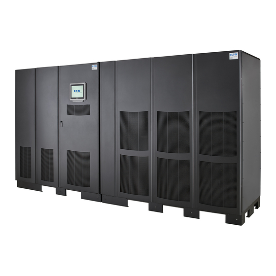
Eaton Power Xpert 9395 UPS Installation And Operation Manual (250 pages)
450–825 kVA
Brand:
Eaton
| Category:
Power Supply
| Size: 15.54 MB
Table of Contents
Table of Contents
5
1 Introduction
15
Figure 1-1. Power Xpert 9395 Three UPM UPS (650-825 Kva)
16
Figure 1-2. Power Xpert 9395 Plus 1 UPS (650-825 Kva) with the Field Installed UPM
16
Figure 1-3. Power Xpert 9395-825/550 Two UPM UPS (450-550 Kva)
17
Figure 1-4. Power Xpert 9395-825/550 Two UPM UPS with the Field Installed UPM (450-825 Kva)
17
UPS Standard Features
18
Sync Control
19
Energy Saver System and High Alert Modes
20
Monitoring and Communication
21
Conventions Used in this Manual
22
Symbols, Controls, and Indicators
23
For more Information
24
2 Safety Warnings
25
3 Ups Installation Plan and Unpacking
29
Installation Considerations
30
Figure 3-1. UPS Cabinet Dimensions - Three UPM (Front View)
32
Figure 3-2. UPS Cabinet Dimensions - Two UPM (Front View)
32
Figure 3-3. UPS Cabinet Dimensions (Right Side View)
33
Figure 3-4. ISBM Section Dimensions (Front View)
33
Figure 3-5. UPM Section Dimensions - Three UPM (Front View)
34
Figure 3-6. UPM Section Dimensions - Two UPM (Front View)
34
Figure 3-7. ISBM Section Dimensions (Top View)
35
Figure 3-8. ISBM Section Dimensions (Bottom View)
35
Figure 3-9. UPM Section Dimensions - Three UPM (Top View)
36
Figure 3-10. UPM Section Dimensions - Two UPM (Top View)
36
Figure 3-11. ISBM Section Center of Gravity - Continuous Static Switch
37
Figure 3-12. UPM Section Center of Gravity - Three UPM
37
Figure 3-13. UPM Section Center of Gravity - Two UPM
38
Figure 3-14. Remote EPO Switch Dimensions
38
UPS System Power Wiring Preparation
39
UPS System Interface Wiring Preparation
52
Inspecting and Unpacking the UPS Cabinet
55
Figure 3-15. UPS Cabinet as Shipped on Pallet (ISBM Section)
57
Figure 3-16. UPS Cabinet as Shipped on Pallet (UPM Section - Three UPM)
58
Figure 3-17. UPS Cabinet as Shipped on Pallet (UPM Section - Two UPM)
59
4 Ups System Installation
61
Figure 4-1. Removing the Left Side Shipping Bracket
62
Figure 4-2. Removing the Right Side Shipping Bracket
63
Figure 4-3. Removing the Three UPM Section Left Side Shipping Bracket
64
Figure 4-4. Removing the Three UPM Section Right Side Shipping Bracket
65
Figure 4-5. Removing the Two UPM Section Left Side Shipping Bracket
66
Figure 4-6. Removing the Two UPM Section Right Side Shipping Bracket
67
Mechanically Joining the Sections
67
Figure 4-7. Section Joining (Three UPM Section Shown)
68
Figure 4-8. ISBM and UPM Sections Joined (Three UPM Section Shown)
69
Electrically Connecting the Sections
70
Figure 4-9. ISBM Section to UPM Section Joining Brackets
70
Figure 4-10. ISBM Section Intercabinet Power Terminal Locations - Common Rectifier Feed, Continuous Static Switch
73
Figure 4-11. ISBM Section Input Power Terminal Detail - Continuous Static Switch
74
Figure 4-12. ISBM Section Battery Input Power Terminal Detail
75
Figure 4-13. ISBM Section Output Power Terminal Detail
76
Figure 4-14. ISBM Section Battery Input Power Terminal Detail
77
Figure 4-15. Pl1 Interface Board Location
78
Figure 4-16. J39 Location on Pl1 Interface Board
78
Field Installed UPM Installation
79
2-Hole Barrel Lug Terminations to Bus Bar Installation
80
Figure 4-17. Typical Bus Bar Barrel Lug Mounting - Hardware Assembly Sequence
80
External Power Wiring Installation
81
Figure 4-18. ISBM and UPM Section Debris Shields
82
Figure 4-19. ISBM Section Conduit and Wire Entry Locations
83
Figure 4-20. ISBM Section Power Terminal Locations - Common Rectifier Feed, Continuous Static Switch
85
Figure 4-21. ISBM Section Power Terminal Detail AA - Common Rectifier Feed, Continuous Static Switch
86
Battery Power Wiring
87
Figure 4-22. UPS Power Terminal Detail BB - Common Battery
88
Figure 4-23. UPS Power Terminal Detail BB - Separate Battery
89
Installing UPS External and Battery Power Wiring
79
Installing Interface Connections
90
TB1, TB2, and TB3 Connections (Other than TB1 Battery Interface Connections)
90
Figure 4-24. ISBM Section Interface Terminal Locations
91
Figure 4-25. Interface Terminal Detail
93
Figure 4-26. Typical Alarm Relay Connection
93
Figure 4-27. Terminal Blocks TB1, TB2, and TB3 Connector Assignments
94
TB1 Battery Interface Connections
95
Figure 4-28. Typical Battery Interface Connection €" Common Battery System
96
Figure 4-29. Typical Battery Interface Connection - Separate Battery System
96
X-Slot Connections
97
Figure 4-30. X-Slot Communication Bays
97
Figure 4-31. REPO Switch
98
Installing a REPO Switch
98
Figure 4-32. Normally-Open REPO Switch Wiring
99
Figure 4-33. Normally Closed REPO Switch Wiring
100
Figure 4-34. Normally Closed and Normally Open REPO Switch Wiring
100
Completing the Installation Checklist
101
Initial Startup
101
Installing Options, Accessories, and Distributed Bypass Control Wiring
101
5 Installing Options and Accessories
105
Installation Notes
105
Installing an Optional Powerware Hot Sync CAN Bridge Card
106
Figure 5-1. Powerware Hot Sync CAN Bridge Card
106
Figure 5-2. Powerware Hot Sync CAN Bridge Card Connections
107
Installing Distributed Bypass Control Wiring
108
Figure 5-3. Distributed Bypass System CAN and Pull-Chain Simplified Interface Wiring
109
Figure 5-4. Distributed Bypass System UPS CAN Wiring Without Mobs
109
Figure 5-5. Distributed Bypass Pull-Chain Wiring Without Mobs
110
Figure 5-6. Distributed Bypass Pull-Chain Wiring with Mobs
111
Installing an Optional Remote Monitor Panel
112
Figure 5-7. Remote Monitor Panel II and Remote Monitor Panel II Terminal Locations
113
Installing an Optional Relay Interface Module
114
Figure 5-8. Remote Monitor Panel II, Relay Interface Module II, or Supervisory Contact Module II Wiring
114
Installing an Optional Supervisory Contact Module
116
Figure 5-9. J1, J2, J3, and J4 15-Pin D-Sub Connectors
116
Figure 5-10. Supervisory Contact Module II Terminal Location
117
Figure 5-11. Supervisory Contact Module II TB2
118
Accessory Mounting Dimensions
119
Figure 5-12. Remote Monitor Panel II Dimensions
119
Figure 5-13. Relay Interface Module II Dimensions
120
Figure 5-14. Supervisory Contact Module II Dimensions
121
6 Understanding Ups Operation
125
UPS System Overview
125
Figure 6-1. Main Elements of the UPS System
125
Single UPS
126
Modes
126
Online Mode
126
Figure 6-2. Path of Current through the UPS in Online Mode
127
Energy Saver System Mode
128
Harmonic Reduction System (HRS)
128
Variable Module Management System
128
Bypass Mode
129
Figure 6-3. Path of Current through the UPS in Bypass Mode
130
Battery Mode
131
Figure 6-4. Path of Current through the UPS in Battery Mode
131
Single UPS System Oneline Configurations
132
Figure 6-5. UPS System - Three UPM, Common Rectifier Feed, Common Battery, Dual-Feed Configuration, Continuous Static Switch
134
Figure 6-6. UPS System - Three UPM, Common Rectifier Feed, Separate Battery, Dual-Feed Configuration, Continuous Static Switch
135
Figure 6-7. Plus 1 UPS System - Four UPM, Common Rectifier Feed, Common Battery, Dual-Feed Configuration, Continuous Static Switch
136
Figure 6-8. Plus 1 UPS System - Four UPM, Common Rectifier Feed, Separate Battery, Dual-Feed Configuration, Continuous Static Switch
137
Figure 6-9. UPS System - Two UPM, Common Rectifier Feed, Common Battery, Dual-Feed Configuration, Continuous Static Switch
138
Figure 6-10. UPS System - Two UPM, Common Rectifier Feed, Separate Battery, Dual-Feed Configuration, Continuous Static Switch
139
Figure 6-11. Plus 1 UPS System - Three UPM, Common Rectifier Feed, Common Battery, Dual-Feed Configuration, Continuous Static Switch
140
Figure 6-12. Plus 1 UPS System - Three UPM, Common Rectifier Feed, Separate Battery, Dual-Feed Configuration, Continuous Static Switch
141
Figure 6-13. UPS System - Three UPM, Common Rectifier Feed, Common Battery, IOM Configuration
142
Figure 6-14. UPS System - Three UPM, Common Rectifier Feed, Separate Battery, IOM Configuration
143
Figure 6-15. Plus 1 UPS System - Four UPM, Common Rectifier Feed, Common Battery, IOM Configuration
144
Figure 6-16. Plus 1 UPS System - Four UPM, Common Rectifier Feed, Separate Battery, IOM Configuration
145
Figure 6-17. UPS System - Three UPM, Separate Rectifier Feed, Separate Battery, Dual-Feed Configuration
146
Figure 6-18. Plus 1 UPS System - Four UPM, Separate Rectifier Feed, Separate Battery, Dual-Feed Configuration, Continuous Static Switch
147
Figure 6-19. 825/550 UPS System - Two UPM, Separate Rectifier Feed, Separate Battery, Dual-Feed Configuration, Continuous Static Switch
148
Figure 6-20. 825/550 UPS System - Three UPM, Separate Rectifier Feed, Separate Battery, Dual-Feed Configuration, Continuous Static Switch
149
Figure 6-21. UPS System - Three UPM, Separate Rectifier Feed, Separate Battery, IOM Configuration
150
Figure 6-22. Plus 1 UPS System - Four UPM, Separate Rectifier Feed, Separate Battery, IOM Configuration
151
Figure 6-23. Simplified Dual-Feed UPS with Maintenance Bypass Panel
152
Multiple UPS Distributed Bypass System
153
Multiple UPS Parallel System Modes
153
Online Mode - Distributed Bypass
154
Bypass Mode - Distributed Bypass
155
Figure 6-24. Path of Current through the Upss in Online Mode - Distributed Bypass
155
Figure 6-25. Path of Current through the Upss in Bypass Mode - Distributed Bypass
156
Battery Mode - Distributed Bypass
157
Figure 6-26. Path of Current through the Upss in Battery Mode - Distributed Bypass
157
Multiple UPS Distributed Bypass System Oneline Configurations
158
Figure 6-27. Typical Distributed Bypass System - Continuous Static Switch, 1+1 and 2+0 Configurations
159
Figure 6-28. Typical Distributed Bypass System - Continuous Static Switch, 2+1 and 3+0 Configurations
160
Figure 6-29. Typical Distributed Bypass System - Continuous Static Switch, 3+1 and 4+0 Configurations
161
7 Ups Operating Instructions
163
UPS Controls and Indicators
163
Figure 7-1. UPS Controls and Indicators - Continuous Static Switch
163
Circuit Breakers
164
Control Panel
164
Using the Control Panel
164
Figure 7-2. UPS Control Panel
164
System Events
165
Figure 7-3. Parts of the LCD
166
Using the LCD and Pushbuttons
166
Figure 7-4. Main Menu and MIMIC Screen (Online Mode)
167
Using the Menu
167
Display Menu Operation
168
Figure 7-5. Load off Screen
171
Figure 7-6. Typical System Status Screen
172
Figure 7-7. Load off Screen
174
Single UPS Operation
175
Enable Energy Saver System Mode from the UPS Command Menu
176
Enable Variable Module Management System Mode from the UPS Command Menu
177
Start Variable Module Management System High Alert Mode from the UPS Command Menu
178
Enable Energy Saver System Mode from the Bypass Command Menu
179
Start Energy Saver System High Alert Mode from the Bypass Command Menu
180
Disable Variable Module Management System Mode from the Bypass Command Menu
181
Starting a Single UPM
182
Transfer from Online to Bypass Mode
183
Transfer from Bypass to Online Mode
184
Single UPM Shutdown
185
UPS and Critical Load Shutdown
186
Using the UPS LOAD off Pushbutton or Command
187
Figure 7-8. REPO Operation
188
Using the Remote Emergency Power-Off Switch
188
Multiple UPS Distributed Bypass Operation
189
Enable Energy Saver System Mode from the UPS Command Menu
190
Enable Variable Module Management System Mode from the UPS Command Menu
191
Start Variable Module Management System High Alert Mode from the UPS Command Menu
192
Enable Energy Saver System Mode from the Bypass Command Menu
193
Start Energy Saver System High Alert Mode from the Bypass Command Menu
194
Disable Variable Module Management System Mode from the Bypass Command Menu
195
Starting a Single UPM
196
Transfer from Online to Bypass Mode
197
Transfer from Bypass to Online Mode
198
Single UPM Shutdown
199
Single UPS Shutdown Using Load off
200
Single UPS Shutdown Using UPM Shutdown
201
Single UPS Restart
202
Charger Control
203
Using the Remote Emergency Power-Off Switch
205
Figure 7-9. UPS Color Touchscreen Control Panel (Typical)
206
Figure 7-10. UPS Color Touchscreen Control Panel (Typical)
207
Using the Color Touchscreen Control Panel
207
Figure 7-11. Parts of the Touch Screen
208
Status Indicators
208
Figure 7-12. Sign in or Password Request Screen
209
Figure 7-13. Home Screen
210
Using the Main Menu Buttons
210
Figure 7-14. Main Menu and Power Maps Screen (Online Mode)
211
Figure 7-15. Output Kva Screen from Home Screen
211
Figure 7-16. Average Efficiency Screen from Home Screen
212
Figure 7-17. Consumption Screen from Home Screen
212
Figure 7-18. Bypass Screen
213
Figure 7-19. Typical Command Confirmation Screen (Charger Off)
213
Power Maps Screen (Bypass Mode)
213
Figure 7-20. Meters Summary Screen
214
Figure 7-21. Input Meters Screen
215
Figure 7-22. Bypass Meters Screen
215
Figure 7-23. Output Meters Screen
216
Figure 7-24. Input Meters Detail Screen
217
Figure 7-25. Select Source Screen
217
Battery Meters Screens
218
Figure 7-26. Battery Meters Screen
218
Figure 7-27. Battery Log Screen
218
Figure 7-28. Battery Log Detail
219
Figure 7-29. Battery Log Summary Screen
219
Figure 7-30. System Events Screen
220
Figure 7-31. User Log Screen
221
Figure 7-32. User Log Detail Screen
221
Figure 7-33. System Status Screen
222
Figure 7-34. Module Controls Screen
222
System Status Screen and Controls
222
Figure 7-35. Module Control Detail Screen
223
Figure 7-36. Online Mode Metering Method Option Screen
223
Figure 7-37. Bypass Mode Metering Method Option Screen
224
Figure 7-38. Settings Screen
224
Figure 7-39. Configuration Options Screen
225
Figure 7-40. Energy Advantage Architecture (EAA) Screen
225
Figure 7-41. Disable ESS Screen
226
Figure 7-42. HRS Metering Screen
226
Figure 7-43. High Alert Timer Screen
227
Figure 7-44. Statistics Basic Screen
227
Figure 7-45. Statistics Data Detail Screen
228
Figure 7-46. ESS Comparison Screen
228
Figure 7-47. UPS Module Map Screen
229
Figure 7-48. System Overview Screen
229
UPS Operation Using the Color Touchscreen Control Panel
230
Figure 8-1. Optional X-Slot Cards
231
8 Communication
231
Enotify Service
232
Figure 8-2. Remote Monitor Panel II
233
Building Alarm Monitoring
233
Figure 8-3. Relay Interface Module II
235
Figure 8-4. Supervisory Contact Module II
236
9 Ups Maintenance
237
Performing Preventive Maintenance
238
Figure 9-1. ISBM Section Air Filter Locations
239
Figure 9-2. Two UPM Section Air Filter Locations
240
Figure 9-3. Three UPM Section Air Filter Locations
241
Figure 9-4. FI-UPM Air Filter Location
242
PERIODIC Maintenance
242
Installing Batteries
243
10 Product Specifications
245
UPS Output
246
Advertisement
Eaton Power Xpert 9395 UPS Installation And Operation Manual (216 pages)
1 UPS 225–275 kVA
Brand:
Eaton
| Category:
UPS
| Size: 2.91 MB
Table of Contents
Save These Instructions
4
Important Safety Instructions
4
Table of Contents
5
1 Introduction
13
Figure 1-1. Power Xpert 9395 Plus 1 UPS (225-275 Kva) Cabinet
14
Control Panel
15
Field Installed UPM
16
Inherent Redundancy
17
Variable Module Management System and High Alert Modes
18
Battery System
19
Symbols, Controls, and Indicators
20
For more Information
21
2 Safety Warnings
23
3 UPS Installation Plan and Unpacking
27
Installation Considerations
28
Figure 3-1. UPS Cabinet Dimensions (Front View)
30
Figure 3-2. UPS Cabinet Dimensions (Right Side View)
30
Figure 3-3. UPS Cabinet Dimensions (Top View)
31
Figure 3-4. UPS Cabinet Dimensions (Bottom View)
31
Figure 3-5. UPS Cabinet Dimensions (Bottom View with Mounting Brackets)
31
Figure 3-6. UPS Cabinet Center of Gravity
32
Figure 3-7. Remote EPO Switch Dimensions
32
UPS System Power Wiring Preparation
33
UPS System Interface Wiring Preparation
43
Distributed Bypass Power Wiring Preparation
44
Inspecting and Unpacking the UPS Cabinet
46
Figure 3-8. Power Xpert 9395 Plus 1 UPS (225-275 Kva) Cabinet as Shipped on Pallet
47
4 UPS System Installation
49
Figure 4-1. Removing the Left Side Shipping Bracket
51
Figure 4-2. Removing the Right Side Shipping Bracket
52
Battery System Installation
53
Figure 4-3. Typical Bus Bar Barrel Lug Mounting - Hardware Assembly Sequence
54
Hole Barrel Lug Terminations to Bus Bar Installation
54
Figure 4-4. Conduit and Wire Entry Locations
56
Figure 4-5. UPS Power Terminal Locations - Common Rectifier Feed
57
Figure 4-6. UPS Power Terminal Detail AA - Common Rectifier Feed
58
Figure 4-7. UPS Power Terminal Locations - Separate Rectifier Feed
59
Figure 4-8. UPS Power Terminal Detail AA - Separate Rectifier Feed
60
Figure 4-9. UPM Rectifier Input Power Terminal Block Detail
60
Battery Power Wiring
61
Figure 4-10. UPS Power Terminal Detail BB - Common Battery
62
Figure 4-11. UPS Power Terminal Detail BB - Separate Battery
63
Installing Interface Connections
63
Figure 4-12. Interface Terminal Locations
65
Figure 4-13. Interface Terminal Detail
67
Figure 4-14. Typical Alarm Relay Connection
67
Figure 4-15. Terminal Blocks TB1, TB2, and TB3 Connector Assignments
68
TB1 Battery Interface Connections
69
Figure 4-16. Typical Battery Interface Connection
70
Figure 4-17. Typical Battery Interface Connection - Separate Battery System
71
X-Slot Connections
71
Figure 4-18. X-Slot Communication Bays
72
Installing a REPO Switch
72
Figure 4-19. REPO Switch
73
Figure 4-20. Normally-Open REPO Switch Wiring
74
Figure 4-21. Normally-Closed REPO Switch Wiring
75
Figure 4-22. Normally-Closed and Normally-Open REPO Switch Wiring
75
5 Installing Options and Accessories
76
Installing Options and Accessories
81
Figure 5-1. Powerware Hot Sync CAN Bridge Card
82
Figure 5-2. Powerware Hot Sync CAN Bridge Card Connections
83
Installing Distributed Bypass Control Wiring
84
Figure 5-3. Distributed Bypass System CAN and Pull-Chain Simplified Interface Wiring
85
Figure 5-4. Distributed Bypass System UPS CAN Wiring Without Mobs
85
Figure 5-5. Distributed Bypass Pull-Chain Wiring Without Mobs
86
Figure 5-6. Distributed Bypass Pull-Chain Wiring with Mobs
87
Installing an Optional Remote Monitor Panel II
89
Figure 5-7. Remote Monitor Panel II and Remote Monitor Panel II Terminal Locations
90
Figure 5-8. Remote Monitor Panel II, Relay Interface Module II, or Supervisory Contact Module II Wiring
90
Installing an Optional Relay Interface Module II
91
Figure 5-9. J1, J2, J3, and J4 15-Pin D-Sub Connectors
92
Figure 5-10. Supervisory Contact Module II Terminal Location
93
Installing an Optional Supervisory Contact Module II
93
Figure 5-11. Supervisory Contact Module II TB2
94
Figure 5-12. Remote Monitor Panel II Dimensions
95
Accessory Mounting Dimensions
95
Figure 5-13. Relay Interface Module II Dimensions
96
Figure 5-14. Supervisory Contact Module II Dimensions
97
Figure 6-1. Main Elements of the UPS System
101
6 Understanding UPS Operation
101
Single UPS
102
Energy Saver System Mode
103
Figure 6-2. Path of Current through the UPS in Online Mode
103
Harmonic Reduction System (HRS)
104
Bypass Mode
105
Battery Mode
106
Single UPS System Oneline Configurations
107
Figure 6‐5. UPS System – Common Rectifier Feed, Common Battery, Dual‐Feed Configuration
108
Figure 6‐6. UPS System – Common Rectifier Feed, Separate Battery, Dual‐Feed Configuration
109
Figure 6‐7. UPS System – Separate Rectifier Feed, Separate Battery, Dual‐Feed Configuration
110
Figure 6‐8. Simplified Dual-Feed UPS with Maintenance Bypass Panel
111
Multiple UPS Distributed Bypass System
112
Online Mode – Distributed Bypass
113
Bypass Mode – Distributed Bypass
114
Figure 6‐10. Path of Current through the Upss in Bypass Mode – Distributed Bypass
115
Battery Mode – Distributed Bypass
116
Multiple UPS Distributed Bypass System Oneline Configurations
117
Figure 6‐12. Typical Distributed Bypass System (1+1 and 2+0 Configurations)
118
Figure 6‐13. Typical Distributed Bypass System (2+1 and 3+0 Configurations)
119
Figure 6‐14. Typical Distributed Bypass System (3+1 and 4+0 Configurations)
120
7 UPS Operating Instructions
121
Control Panel
122
Status Indicators
123
Using the LCD and Pushbuttons
124
Using the Menu
125
Display Menu Operation
126
Load off Screen
129
Figure 7‐6. Typical System Status Screen
130
Load off Screen
132
Single UPS Operation
133
Enable Energy Saver System Mode from the UPS Command Menu
134
Disable Energy Saver System Mode from the UPS Command Menu
135
Enable Variable Module Management System Mode from the UPS Command Menu
136
Start Variable Module Management System High Alert Mode from the UPS Command Menu
137
Enable Energy Saver System Mode from the Bypass Command Menu
138
Start Energy Saver System High Alert Mode from the Bypass Command Menu
139
Disable Variable Module Management System Mode from the Bypass Command Menu
140
Starting the Upms
141
Starting a Single UPM
142
Transfer from Online to Bypass Mode
143
Transfer from Bypass to Online Mode
144
Single UPM Shutdown
145
Single UPM Restart
146
UPS and Critical Load Shutdown
147
Using the UPS LOAD off Pushbutton or Command
148
Using the Remote Emergency Power-Off Switch
150
Multiple UPS Distributed Bypass Operation
151
Enable Energy Saver System Mode from the UPS Command Menu
152
Disable Energy Saver System Mode from the UPS Command Menu
153
Enable Variable Module Management System Mode from the UPS Command Menu
154
Start Variable Module Management System High Alert Mode from the UPS Command Menu
155
Enable Energy Saver System Mode from the Bypass Command Menu
156
Disable Energy Saver System Mode from the Bypass Command Menu
157
Enable Variable Module Management System Mode from the Bypass Command Menu
158
Start Variable Module Management System High Alert Mode from the Bypass Command Menu
159
Starting a Single UPM
161
Transfer from Online to Bypass Mode
162
Transfer from Online to Bypass Mode and Shut down Upms
163
Single UPM Restart
164
Single UPS Shutdown Using Load off
165
Single UPS Shutdown Using UPM Shutdown
166
Single UPS Restart
167
UPS and Critical Load Shutdown
168
Using the UPS LOAD off Pushbutton or Command
169
Using the Remote Emergency Power-Off Switch
171
Color Touchscreen Control Panel
172
Using the Color Touchscreen Control Panel
173
Status Indicators
174
Figure 7‐12. Sign in or Password Request Screen
175
Using the Main Menu Buttons
176
Power Maps Screen (Online Mode)
177
Figure 7‐16. Average Efficiency Screen from Home Screen
178
Power Maps Screen (Bypass Mode)
179
Meters Summary Screen
180
Input Meters Screen
181
Figure 7‐23. Output Meters Screen
182
Input Meters Detail Screen
183
Battery Meters Screens
184
Figure 7‐28. Battery Log Detail
185
System Events Main Screen
186
Figure 7‐31. User Log Screen
187
System Status Screen and Controls
188
Figure 7‐35. Module Control Detail Screen
189
Settings Screen
190
Configuration Options Screen
191
Figure 7‐41. Disable ESS Screen
192
Statistics Basic Screen
193
ESS Comparison Screen
194
UPS Module Map Screen
195
UPS Operation Using the Color Touchscreen Control Panel
196
8 Communication
199
Enotify Service
200
Power Management Software
201
Remote Monitor Panel II
202
Relay Interface Module II
204
Supervisory Contact Module II
205
9 UPS Maintenance
207
Performing Preventive Maintenance
208
PERIODIC Maintenance
209
Recycling the Used Battery or UPS
210
10 Product Specifications
211
UPS Output
212
11 Warranty
213
Advertisement
Related Products
Eaton Power Xpert Series
Eaton Power Xpert 825/550
Eaton Powerware Prestige Series 1500 VA
Eaton Powerware Prestige Series 650 VA
Eaton Powerware BladeUPS 12i
Eaton Power Xpert 9395 UPS Plus 1
Eaton Power Xpert 9395
Eaton Power Xpert 9395P-900 Three UPM
Eaton Power Xpert 9395-300
Eaton Power Xpert 9395P-600/500
Eaton Categories
UPS
Circuit breakers
Industrial Equipment
Switch
Industrial Electrical
More Eaton Manuals
Login
Sign In
OR
Sign in with Facebook
Sign in with Google
Upload manual
Upload from disk
Upload from URL