Table of Contents
Advertisement
Advertisement
Table of Contents

Related Manuals for Rosslare AC-Q74


Summary of Contents for Rosslare AC-Q74
- Page 1 2012 March AC-Q74 Secured Access Control Unit Installation and Programming Manual...
- Page 2 ROSSLARE. ROSSLARE reserves the right to revise and change this document at any time, without being obliged to announce such revisions or changes beforehand or after the fact.
-
Page 3: Table Of Contents
Environmental Characteristics ..........10 Mechanical Characteristics ............. 10 Key Features .............. 11 Installation ..............12 Mounting the AC-Q74 Controller .......... 12 Wiring the AC-Q74 ............... 13 Normal, Secure, & Master Users ....... 15 Modes of Operation ..........16 Normal Mode ............... 16 Bypass Mode ................ - Page 4 Table of Contents 10. PC-25T Power Supply Unit ......... 22 11. Programming the AC-Q74 ......... 23 11.1 Entering Programming Mode ..........24 11.2 Exiting Programming Mode ........... 24 11.3 Changing Lock Strike Code 1 ..........25 11.4 Changing Lock Strike Code 2 ..........26 11.5...
- Page 5 PCB Mounting Dimensions ............ 39 13. PS-25T with Enclosures ..........40 13.1 PS-A25T ................40 13.1.1 PS-A25T ..................40 13.2 PS-C25T/25TU ..............40 13.2.1 PS-C25T ..................41 13.2.2 PS-C25TU ..................41 13.3 Wiring Diagram..............42 Limited Warranty ............43 AC-Q74 Installation and Programming Manual...
- Page 6 List of Figures List of Figures Figure 1: Drill Holes for AC-Q74 Controller ............. 12 Figure 2: Wiring Diagram and Schematic for the AC-Q74 ....... 13 Figure 3: Dimensions for PCB Mounting ............39 Figure 4: PS-A25T .................... 40 Figure 5: PS-C25T/C25TU ................41 Figure 6: Wiring Diagram and Schematic for PC-25T, PS-A25T, PS-C25T, and PS- 25TU ....................
- Page 7 List of Tables List of Tables Table 1: Wire Color Guide ................13 Table 2: Programming Menus................23 AC-Q74 Installation and Programming Manual...
- Page 8 ROSSLARE ENTERPRISES LIMITED and/or its related companies and/or subsidiaries’ (hereafter:"ROSSLARE") exclusive warranty and liability is limited to the warranty and liability statement provided in an appendix at the end of this document.
-
Page 9: Introduction
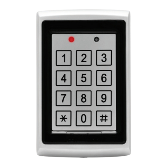
Introduction Introduction The AC-Q74 is a vandal resistant proximity card and keypad access control unit suitable for external applications. The unit accepts up to 500 users and provides entry via the use of proximity cards and/or PIN codes. It is designed for high security applications, due to the fact that lock... -
Page 10: Technical Specifications
2.5 in. (65 mm) Modulation ASK at 125 kHz Compatible Cards All 26-Bit EM cards * Measured using Rosslare Proximity Card (AT-11/12) or equivalent. Range also depends on electrical environment and proximity to metal. Environmental Characteristics Operating Temperature: -25°F to 145°F (-31°C to 63°C) -
Page 11: Key Features
Key Features Key Features Here are some of the AC-Q74’s key features: Bi-directional communication with PC-25T Built-in Proximity Card Reader (125 KHz ASK Modulation) Built-in Piezoelectric keypad for PIN code entry Internal Buzzer Comes with security screw and security screw tool Two status/programming interface LEDs ... -
Page 12: Installation
4. Wire the controller according the wiring instructions of the following page. 5. Return the front cover of the AC-Q74 to the mounted back plate. 6. Secure the front cover by using the supplied security screw in the Installation Kit. An L-Shaped tool is provided for use when tightening the security screw. -
Page 13: Wiring The Ac-Q74
BLACK GROUND WHITE GREEN 3. Trim and cover all conductors that are not used. A typical wiring diagram is shown in Figure 2. Figure 2: Wiring Diagram and Schematic for the AC-Q74 ROSSLARE PC-25T AC-Q74 AC-Q74 Installation and Programming Manual... - Page 14 Installation For other wiring diagram examples, refer to the Support section of the Rosslare website: www.rosslaresecurity.com/support/ AC-Q74 Installation and Programming Manual...
-
Page 15: Normal, Secure, & Master Users
Normal, Secure, & Master Users Normal, Secure, & Master Users The AC-Q74 accepts up to 500 users and provides entry via the use of proximity cards and/or PIN codes. Each user is provided with two code memory slots, Memory Slot 1 (Primary code) and Memory Slot 2 (Secondary code). -
Page 16: Modes Of Operation
Modes of Operation Modes of Operation The AC-Q74 has three modes of operation: Normal Mode Bypass Mode Secure Mode Normal Mode Mode Door The Mode LED is green. GREEN Normal mode is the default mode. In Normal mode, the door is locked until a Primary code is presented to the controller. -
Page 17: Secure Mode
After entering their Primary code, the Door LED flashes green for 10 seconds, during which the Secondary code must be entered. Master Users only need to present their Proximity Card or PIN code once to gain entry. AC-Q74 Installation and Programming Manual... -
Page 18: Changing The Modes Of Operation
To change from Secure mode to Normal mode: Mode Door 1. Enter the 4-digit Normal/Secure code. Mode Door Mode LED flashes green. GREEN 2. Press the “#” key to confirm the mode change. Mode Door The Mode LED turns green. GREEN AC-Q74 Installation and Programming Manual... -
Page 19: Changing From Normal Mode To Bypass Mode
To change from By pass mode to Normal mode: Mode Door 1. Enter the 4-digit Normal/Bypass code. ORANGE Mode Door Mode LED flashes green. GREEN 2. Press the “#” key to confirm the mode change. Mode Door The Mode LED turns green. GREEN AC-Q74 Installation and Programming Manual... -
Page 20: Request To Exit (Rex) Function
REX button is released, plus the Lock Strike Release Time. In this case, the Lock Strike Relay only begins its count down once the REX button is released. AC-Q74 Installation and Programming Manual... -
Page 21: Case And Back Tamper
For example, while in Secure mode, using the Lock Strike codes to clear tamper event does not work because the Strike codes does not work in Secure mode. However, applying a Master code or Secure code clears the tamper event in Secure mode. AC-Q74 Installation and Programming Manual... -
Page 22: Pc-25T Power Supply Unit
AC-Q74. It is designed to operate indoors and installed within the premises to be secured. The AC-Q74 must be used with PC-25T, which provides its Lock Strike output, Request to Exit (REX) Input and Bell Function. -
Page 23: Programming The Ac-Q74
During the AC-Q74's manufacturing process certain codes and settings are pre-programmed. These settings are the called the Default Factory Settings. Table 2 shows the names of all the AC-Q74 menus. It also shows of all the AC-Q74’s default factory codes and settings. Table 2: Programming Menus... -
Page 24: Entering Programming Mode
Door LED turns green and the AC-Q74 enters GREEN Programming Mode. • The AC-Q74 must be in Normal Mode to enter Programming mode. • The factory default Programming code is 1234. • If a Programming code is not entered within 5 seconds, the AC- Q74 returns to Normal mode 11.2... -
Page 25: Changing Lock Strike Code 1
Wrong entries may reset the controller back to Normal mode. While in Programming mode, if no key is pressed for 1 minute, the AC-Q74 exits Programming mode and returns to Normal mode. A short press on key may also return the system to Normal mode ... -
Page 26: Changing Lock Strike Code 2
To change the Programming code: Mode Door 1. Enter Programming mode. GREEN 2. Press “3” to enter Menu 3. Mode Door The Mode LED turns green. GREEN GREEN ? ? ? ? 3. Enter the new 4-digit Programming code. AC-Q74 Installation and Programming Manual... -
Page 27: Changing The Normal/Secure Code
The Door LED turns off. GREEN The Mode LED turns green. Code 0000 erases the Normal/Secure code. 11.7 Changing the Normal/Bypass Code To change the Normal/By pass code: Mode Door 1. Enter Programming mode. GREEN AC-Q74 Installation and Programming Manual... - Page 28 3. Enter the new 4-digit Normal/Bypass code. The system returns to Normal mode. You hear three beeps Mode Door The Door LED turns off. GREEN The Mode LED turns green. Code 0000 erases the Normal/Bypass code. AC-Q74 Installation and Programming Manual...
-
Page 29: Defining The Lock Settings
For example, 0012 means Fail Secure Operation, and a 12 second Lock Strike release time. Mode Door The system returns to Normal mode. GREEN You hear three beeps. The Door LED turns off. The Mode LED turns green. AC-Q74 Installation and Programming Manual... -
Page 30: Enrolling Primary & Secondary Codes
The Code Search Method is mainly used when enrolling a user’s Secondary code and the User Slot code is unknown. The Search method only works if a user’s Primary code is already enrolled but the Secondary code is not (see Section 11.9.5). AC-Q74 Installation and Programming Manual... -
Page 31: Enrolling Primary And Secondary Codes Using The Standard Method
“#” key to move to the next slot number (see Step 4). If you do not wish to continue enrolling codes, press the “#” key twice and the controller returns to Normal mode. AC-Q74 Installation and Programming Manual... -
Page 32: Enrolling Secondary Codes Using The Code Search Method
If the Secondary code is valid the controller beeps three times and returns to Normal mode. If the Secondary code is invalid, the controller sounds a long beep and the AC-Q74 continues to wait for a valid Secondary code to be entered. AC-Q74 Installation and Programming Manual... -
Page 33: Deleting Primary & Secondary Codes
Programming ORANGE code to confirm the deletion. If the User Slot is empty, you hear a long beep and the AC-Q74 returns to Normal mode. ? ? ? ? 4. Enter your Programming code to confirm the deletion. -
Page 34: Deleting Primary And Secondary Codes Using The Code Search Method
5. Enter your Programming code to confirm the deletion. If the Programming code is valid, you hear three beeps and the AC-Q74 returns to Normal Mode. If the Programming code is invalid, you hear a long beep and the AC-Q74 returns to Normal mode. -
Page 35: Return To Factory Default Settings
Normal mode without erasing the memory of the controller. 11.12 Replacing a Lost Programming Code The AC-Q74 must be in Normal mode; otherwise, this does not work. Make sure that the Mode LED is green before proceeding. To replace a lost programming code: 1. -
Page 36: Replacing A Lost Normal/Secure Code
Programming the AC-Q74 11.13 Replacing a Lost Normal/Secure Code The AC-Q74 must be in Secure Mode; otherwise, this does not work. Make sure that the Mode LED is red before proceeding. To replace a lost normal/ secure code: 1. Remove power from the Power Supply Unit (PC-25T). -
Page 37: Power Supply Installation Instructions
12.1 Introduction and Key Features The PC-25T Power Supply is designed for use with all Rosslare secured series stand-alone access control units. The PC-25T contains two power supplies. One power supply is for the lock strike, the other is for the access control unit (ACU). -
Page 38: Electrical Specifications
Power LED & Power LED indicator Speaker Output 8 OHM, 0.25 W (minimum) For bell, chime and siren alerts 12.3 Environmental Specifications Operating -10°C to 50°C (14°F to 122°F) Temperature Operating 0 to 95% (non-condensing) Humidity AC-Q74 Installation and Programming Manual... -
Page 39: Mechanical Specifications
Communication wiring (C1 & C2) should be twisted Pair, 22 Gage, shielded or unshielded. 12.6 PCB Mounting Dimensions Dimensions for PCB mounting holes are provided in Figure 3: Figure 3: Dimensions for PCB Mounting 66mm (2.6”) AC-Q74 Installation and Programming Manual... -
Page 40: Ps-25T With Enclosures
EN 61558-2-6:1997 13.2 PS-C25T/25TU The PS-C2 and PS-C25TU enclosures include a built-in speaker and enough room for a CE or UL approved transformer as well as a lead acid backup battery (up to 7 AH). AC-Q74 Installation and Programming Manual... -
Page 41: Ps-C25T
States a UL approved transformer is recommended. The enclosure weight and dimensions are provided below: Dimensions: Length: 225 mm (8.86”) Width: 220 mm (8.66”) Depth: 82 mm (3.2”) Weight: 2.45 kg (2.7 lbs) PS-C25T 1.5 kg (3.3 lbs) PS-C25U AC-Q74 Installation and Programming Manual... -
Page 42: Wiring Diagram
PS-25T with Enclosures 13.3 Wiring Diagram A wiring diagram and schematic for the PC-25T, PS-A25T, PS-C25T, and PS-C25TU is provided in Figure 6. Figure 6: Wiring Diagram and Schematic for PC-25T, PS-A25T, PS-C25T, and PS-25TU ROSSLARE PC-25T AC-Q74 Installation and Programming Manual... -
Page 43: Limited Warranty
ARRANTY EMEDY OVERAGE In the event of a breach of warranty, ROSSLARE will credit Customer with the price of the Product paid by Customer, provided that the warranty claim is delivered to ROSSLARE by the Customer during the warranty period in accordance with the terms of this warranty. Unless otherwise requested by a ROSSLARE representative, return of the failed product(s) is not immediately required. - Page 44 ROSSLARE or a ROSSLARE authorized service center. XCLUSIONS AND IMITATIONS ROSSLARE shall not be responsible or liable for any damage or loss resulting from the operation or performance of any Product or any systems in which a Product is incorporated. This warranty shall not...
- Page 45 In no event shall ROSSLARE be liable for damages in excess of the purchase price of the product, or for any other incidental, consequential or special damages, including but not limited to loss of...
- Page 46 Rosslare Enterprises Ltd. support.la@rosslaresecurity.com Kowloon Bay, Hong Kong Tel: +852 2795-5630 China Fax: +852 2795-1508 support.apac@rosslaresecurity.com Rosslare Electronics (Shenzhen) Ltd. Shenzhen, China United States and Tel: +86 755 8610 6842 Canada Fax: +86 755 8610 6101 support.cn@rosslaresecurity.com Rosslare Security Products, Inc.
Need help?
Do you have a question about the AC-Q74 and is the answer not in the manual?
Questions and answers