
Related Manuals for Rosslare AY-D09M


Summary of Contents for Rosslare AY-D09M
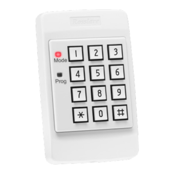
- Page 1 AY-Dx9M Family Indoor Multi-Format Readers Installation and Programming Manual Models: AY-D09M AY-D19M...
- Page 2 ROSSLARE. ROSSLARE reserves the right to revise and change this document at any time, without being obliged to announce such revisions or changes beforehand or after the fact.
-
Page 3: Table Of Contents
Table of Contents Table of Contents Introduction ..............7 Reader/Controller Types............7 Key Features ................7 Box Content ................8 Ancillary Equipment ..............8 Technical Specifications ..........9 Installation ..............11 Mounting and Wiring the AY-Dx9M ........11 Transmit Mode ............13 Programming the AY-Dx9M ........ - Page 4 List of Figures List of Figures Figure 1: AY-Dx9M Layout ................11 Figure 2: AY-Dx9M Wiring ................12 AY-Dx9M Family Installation and Programming Manual...
- Page 5 List of Tables List of Tables Table 1: Programming Menus................14 Table 2: Keypad Transmission Format .............. 17 AY-Dx9M Family Installation and Programming Manual...
- Page 6 ROSSLARE exclusive warranty and liability is limited to the warranty and liability statement provided in an appendix at the end of this document.
-
Page 7: Introduction
The AY-D19M supports multiple proximity card formats to provide a high level of compatibility and connectivity with host controllers. Reader/Controller Types The two types of units described in this manual are: Keypad Type PIN Proximity AY-D09M Standard AY-D19M Standard ... -
Page 8: Box Content
Ancillary Equipment Additional non-supplied equipment required: Compatible host controller Power supply – 5 to 16 VDC (from a regulated power supply) Other Rosslare accessories can be found at Rosslare's website: http://www.rosslaresecurity.com AY-Dx9M Family Installation and Programming Manual... -
Page 9: Technical Specifications
1 to 8 Keys BCD, Clock & Data Tamper Only with Rosslare controllers AC-015, AC- 020, and AC-115 Measured using a Rosslare proximity card or equivalent. Range also depends on electrical environment and proximity to metal AY-Dx9M Family Installation and Programming Manual... - Page 10 Operating Temp. Range -31°C to 63°C (-24°F to 145°F) Operating Humidity Range 0 to 95% (non-condensing) Dimensions AY-D09M AY-D19M Length x Width x Depth 122 x 75 x 24 mm (4.8 x 3.0 x 0.9 in.) Weight 110 g (3.9 oz) 117 g (4.1 oz)
-
Page 11: Installation
Installation Installation Installation of an RFID reader adjacent to metallic surfaces might alter the reader’s specifications. To diminish this interference, use a plastic spacer when mounting the reader. Mounting and Wiring the AY-Dx9M The AY-Dx9M is designed to be easily mounted to a US Gang Box. Before starting, select the location to mount the AY-Dx9M reader. - Page 12 Installation 3. Pass the wires through the exit/entry holes and attach them to the reader’s terminal blocks (Figure 2). Figure 2: AY-Dx9M Wiring To Controller 4. Replace the reader's bezel and replace the factory default screw with the security screw that is provided in the installation kit. A security screw tool is also provided in the installation kit.
-
Page 13: Transmit Mode
Transmit Mode Transmit Mode When the AY-Dx9M is in Transmit mode, it is ready to receive data from a presented proximity card (AY-D19M only) or an entered PIN code. Mode Prog When the reader is in Transmit mode, the Mode LED is red and the Program LED is off. When a proximity card or keyboard entry is being transmitted, the Mode LED flashes green. -
Page 14: Programming The Ay-Dx9M
Table 1: Programming Menus Menu Description Menu Number Selecting Keypad Transmission Format Single Key, Wiegand 6-Bit (Rosslare format) Single Key, Wiegand 6-Bit with Nibble + Parity Bits Single Key, Wiegand 8-Bit, Nibbles Complemented 4 Keys Binary + Facility Code, Wiegand 26-Bit... -
Page 15: Entering Programming Mode
Programming the AY-Dx9M Entering Programming Mode To enter Programming mode: 1. Press # for 2 seconds. Mode Prog The Mode LED turns off and the Program LED turns red. 2. Enter your 4-digit Programming code. If the Programming code is valid, the Mode Prog Green... -
Page 16: Selecting Keypad Transmission Format
Programming the AY-Dx9M Selecting Keypad Transmission Format The AY-Dx9M has eight different keypad transmission selectable formats (see Section 5.3.1). To select a key pad transmission format: Prog 1. Enter Programming mode. Mode Green 2. Press 1 to enter Menu 1. Mode Prog 3. -
Page 17: Keypad Transmission Format Option Number
Table 2: Keypad Transmission Format Keypad Transmission Format Option Number Single Key, Wiegand 6-Bit (Rosslare Format) Single Key, Wiegand 6-Bit with Nibble + Parity Bits Single Key, Wiegand 8-Bit, Nibbles Complemented 4 Keys Binary + Facility code, Wiegand 26-Bit... -
Page 18: Single Key, Wiegand 8-Bit, Nibbles Complemented
Programming the AY-Dx9M 5.3.1.2 Single Key, Wiegand 6-Bit, Nibble & Parities Each key press immediately sends 4 bits with 2 parity bits added; even parity for the first 3 bits and odd parity for the last 3 bits. 0 = 0 0000 1 6 = 1 0110 0 1 = 0 0001 0 7 = 1 0111 1... -
Page 19: To 5 Keys + Facility Code, Wiegand 26-Bit
Programming the AY-Dx9M If the entry of the 4-digit keypad PIN code is disrupted and no number key is pressed within 5 seconds, the keypad clears the PIN code entry buffer, generates a beep, and is ready to receive a new 4-digit keypad PIN code. -
Page 20: Keys Bcd And Parity Bits, Wiegand 26-Bit
Programming the AY-Dx9M Where: EP = Even parity for first 12 bits OP = Odd parity for last 12 bits F = 8-bit Facility code A = 24-bit code generated from keyboard 5.3.1.6 6 Keys BCD and Parity Bits, Wiegand 26-Bit Sends buffer of 6 keys, adds parity and sends a 26-bit BCD message. - Page 21 Programming the AY-Dx9M The MD-P64 interface unit outputs the data received to 7 outputs emulating a keyboard. The interface unit does not affect any data that it receives from the proximity reader whether it is Wiegand 26-Bit or Clock & Data. Key pressed = ASCII Value 0 = '0' (0x30 hex) 6 = '6' (0x36 hex)
-
Page 22: Selecting Proximity Card Transmission Format (Ay-D19M Model Only)
Programming the AY-Dx9M Selecting Proximity Card Transmission Format (AY-D19M model only) The AY-D19M has three different selectable proximity card transmission formats. Option 1 – Wiegand 26-Bit Option 2 – Clock & Data Option 3 – Wiegand Card + PIN To select the Prox imity Card transmission format: Mode Prog... - Page 23 Programming the AY-Dx9M buffer and the PIN code entry buffer, generates a medium length beep, and is ready to receive a new card. The keypad PIN code can be one to five digits long in the range of 0 to 99,999. When entering a keypad PIN code, # must be pressed to signify the end of the PIN entry.
-
Page 24: Changing The Programming Code
Programming the AY-Dx9M Where: A = First key entered B = Second key entered EP = Even parity for first 12 bits OP = Odd parity for last 12 bits Changing the Programming Code To change the Programming code: Prog 1. -
Page 25: Return To Factory Default Settings
Programming the AY-Dx9M 3. Enter the new 3-digit code you wish to set as the Facility code. Mode Prog One beep is emitted on success. The system returns to Transmit mode. Facility codes can be in the range between 000 and 255. Return to Factory Default Settings You must be very careful before using this command! Doing so erases the entire memory, which includes all user and special... -
Page 26: Replacing A Lost Programming Code
Programming the AY-Dx9M Replacing a lost Programming Code In the event that the Programming code is forgotten, the AY-Dx9M may be reprogrammed in the field using the following instructions: 1. Remove power from the reader. 2. Activate the tamper by removing the reader from the wall or removing the reader's case. -
Page 27: Limited Warranty
The full ROSSLARE Limited Warranty Statement is available in the Quick Links section on the ROSSLARE website at www.rosslaresecurity.com. Rosslare considers any use of this product as agreement to the Warranty Terms even if you do not review them. AY-Dx9M Family Installation and Programming Manual... - Page 28 +86 755 8610 6842 Fax: +86 755 8610 6101 Rosslare Security Products, Inc. support.cn@rosslaresecurity.com Southlake, TX, USA Toll Free: +1-866-632-1101 India Local: +1-817-305-0006 Rosslare Electronics India Pvt Ltd. Fax: +1-817-305-0069 Tel/Fax: +91 20 40147830 support.na@rosslaresecurity.com Mobile: +91 9975768824 Europe sales.in@rosslaresecurity.com Rosslare Israel Ltd.
Need help?
Do you have a question about the AY-D09M and is the answer not in the manual?
Questions and answers