
Subscribe to Our Youtube Channel
Related Manuals for JAI CM-200GE


Summary of Contents for JAI CM-200GE
- Page 1 User's Manual CM-200GE CB-200GE CM-200GE-RA CB-200GE-RA Digital Monochrome / Color Progressive Scan GigE Vision Camera Document Version: 2.2 CMB-200GE_Ver.2.2_Aug2018...
- Page 2 JAI Ltd., Japan and may only be used by the purchasers of the product. JAI Ltd., Japan makes no warranty for the use of its product and assumes no responsibility for any errors which may appear or for damages resulting from the use of the information contained herein.
- Page 3 CM-200GE /CM-200GE-RA Supplement The following statement is related to the regulation on “ Measures for the Administration of the control of Pollution by Electronic Information Products “ , known as “ China RoHS “. The table shows contained Hazardous Substances in this camera.
- Page 4 CB-200GE / CB-200GE-RA Supplement The following statement is related to the regulation on “ Measures for the Administration of the control of Pollution by Electronic Information Products “ , known as “ China RoHS “. The table shows contained Hazardous Substances in this camera. mark shows that the environment-friendly use period of contained Hazardous Substances is 15 years.
-
Page 5: Table Of Contents
7.2. Vertical Binning (CM-200GE/CM-200GE-RA only)..........- 20 - 7.3. Digital Video Output (Bit Allocation) ..............- 21 - 7.3.1 Bit Allocation (Pixel Format / Pixel Type) – CM-200GE/CM-200GE-RA (monochrome) - 21 - 7.3.1.2 GVSP_PIX_MONO10 (10bit) ..............- 21 - 7.3.1.3 GVSP_PIX_MONO10_PACKED (10 bit ) ............ - Page 6 12. External Appearance and Dimensions ............... - 60 - 12.1. CM-200GE and CB-200GE ................- 60 - 12.2. CM-200GE-RA and CB-200GE-RA ..............- 61 - 13. Specifications ................... - 62 - 13.1 Spectral response ..................- 62 - 13.2 Specification table ..................- 63 - 14.
-
Page 7: Jai Gige ® Vision Camera Operation Manuals
Describes the network interface www.jai.com User’s manual is available at JAI SDK & Control Tool User Guide and JAI SDK Getting Started Guide are provided with the JAI SDK which is available at www.jai.com. Introduction GigE Vision is a standard interface which uses Gigabit Ethernet for machine vision applications. It was developed primarily by AIA (Automated Imaging Association) members. -
Page 8: Camera Operation
CB-200GE/CB-200GE-RA provide a frame rate of 25 frames/second at full resolution. Using vertical binning (CM-200GE/CM-200GE-RA only) and partial scan provides higher frame rates. The 1/1.8" CCD with square pixels offers a superb image quality. The high-speed shutter function and asynchronous random trigger mode allows the camera to capture high quality images of fast moving objects. -
Page 9: Main Features
24 frames/second with external trigger and full resolution • +24dB Gain and noise reduction circuit built-in • Increased frame rate with vertical binning (CM-200GE/CM-200GE-RA only) and partial scan • Exposure time from 64μs to 2 sec. using Pulse Width Control trigger mode •... -
Page 10: Locations And Functions
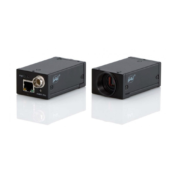
CM-200GE/CM-200GE-RA/CB-200GE/CB-200GE-RA 4. Locations and Functions 4.1. CM-200GE/CB-200GE ③ ⑧ ④ GigE ⑨ POWER / TRIG ① ② ⑦ ⑤ ⑥ Lens mount C-mount (Note *1) CCD sensor 1/1.8 inch CCD sensor 12-pin connector DC +12V to +24V power and GPIO interface ... -
Page 11: Cm-200Ge-Ra/Cb-200Ge-Ra
*3) Note: The depth of holes are 3.5mm. When the tripod adapter plate MP-40 or MP-41 is used with, use attached screws. If installing the camera directly, please use the depth of screws is less 3.5mm. Fig.2 Locations ( CM-200GE-RA / CB-200GE-RA ) - 9 -... -
Page 12: Rear Panel Indicator
CM-200GE/CM-200GE-RA/CB-200GE/CB-200GE-RA 4.3. Rear panel indicator. The rear panel mounted LED provides the following information: Amber: Power connected - initiating Steady green : Camera is operating in Continuous mode Flashing green: The camera is receiving external trigger GigE... -
Page 13: Pin Assignment
5.2. Digital Output Connector for Gigabit Ethernet Type: RJ-45 HFJ11-1G02E-L21RL or equivalent The CM-200GE and CB-200GE cameras also accept industrial RJ-45 connectors with thumbscrews. This assures that the connector does not come undone in tough industrial environments. Please contact the nearest JAI distributor for details on recommended industrial RJ-45 connectors. -
Page 14: Input And Output Interface
End point counter 0 Counter 0 clear Bypass 1 - 4095 1/2 to 1/4096 Fig.6. GPIO bloack The input and output settings for the CM-200GE and CB-200GE series have been fixed as follows. Line Signal Connector Line 3 Optical Out 1... -
Page 15: 12-Bit Counter
CM-200GE/CM-200GE-RA/CB-200GE/CB-200GE-RA 6.1.2 12-bit Counter A 25MHz clock or the camera pixel clock (65MHz) can be used as a source. The counter has a “Divide by N”, where N has the range 1 through 4096, allowing a wide range of clock frequencies to be programmed. -
Page 16: Opto-Isolated Inputs/Ouputs
In the above example, N is “0” which is no delay. The length, in this case, is 102 clocks. These settings can be achieved by JAI Control tool which is the part of JAI SDK. 6.2. Opto-isolated Inputs/Ouputs The control interface of the C3 GigE Vision camera series has opto-isolated inputs and outputs, providing galvanic separation between the camera's inputs/outputs and peripheral equipment. -
Page 17: Recommended External Input Circuit Diagram For Customer
CM-200GE/CM-200GE-RA/CB-200GE/CB-200GE-RA 6.2.1 Recommended External Input circuit diagram for customer E XTE RN A L IN P U T Use r JA I sid e C3_Series CAMER A sid e h iro s e -12 c onne c t o r + 3 . -
Page 18: Optical Interface Specifications
CM-200GE/CM-200GE-RA/CB-200GE/CB-200GE-RA 6.2.3 Optical Interface Specifications The relation of the Input signal and the output signal through optical interface is as follows. Conditions for Input Input Line Voltage Range +3.3v ~ +24V Input Current 6mA ~ 30mA Minimum Input Pulse Width to Turn ON 0.5us... -
Page 19: Configuring The Gpio Module (Register Settings)
CM-200GE/CM-200GE-RA/CB-200GE/CB-200GE-RA 6.4. Configuring the GPIO module (register settings) 6.4.1 Input/Output Signal Selector Line selector This sets the input and output to the external equipment. Line 3 through line 6 are already allocated as below. Line source This sets which signal can be fed through selected output, external or internal. -
Page 20: Gpio Plus Pwc Shutter
CM-200GE/CM-200GE-RA/CB-200GE/CB-200GE-RA 6.5.2 GPIO Plus PWC shutter Example: 10µs unit pulse width exposure control (PWC). Pixel clock is 65MHz. 650 clocks (750-100) equals 10µs. Feature Value c)Acquisition Trigger Trigger Mode Trigger controls selector Acquisition Exposure Pulse width control Trigger Control Mode... -
Page 21: Internal Trigger Generator
CM-200GE/CM-200GE-RA/CB-200GE/CB-200GE-RA 6.5.3 Internal Trigger Generator Create a trigger signal and trigger the camera Feature Value c)Acquisition Trigger Trigger Mode Trigger controls selector Pulse Generators Pulse Pulse Generator 0 Selector Generator selector Clock Choice 1 = Pixel Clock (65MHz) Counter Dividing Value... -
Page 22: Image Output Signal
Fig. 11 shows the binning principle. Resolution and frame rate combinations shown below table. Fig.16. CM-200GE/CM-200GE-RA binning. The CM-200GE/CM-200GE-RA has ON or OFF function for Vertical Binning: Setting Value for Register address 0xA084 Resolution (pixels) Frame rate Off (no binning) 0x01 1624(h) x 1236(v) 24.98 fps. -
Page 23: Digital Video Output (Bit Allocation)
Analog Signal [mV] Fig. 17. Digital Output 7.3.1 Bit Allocation (Pixel Format / Pixel Type) – CM-200GE/CM-200GE-RA (monochrome) In the GigE Vision Interface, GVSP (GigE Vision Streaming Protocol) is used for an application layer protocol relying on the UDP transport layer protocol. It allows an application to receive image data, image information and other information from a device. -
Page 24: Gvsp_Pix_Mono10_Packed (10 Bit )
CM-200GE/CM-200GE-RA/CB-200GE/CB-200GE-RA 7.3.1.3 GVSP_PIX_MONO10_PACKED (10 bit ) 2 3 4 5 6 7 8 9 0 1 X X 0 1 X X 2 3 4 5 6 7 8 9 2 3 4 5 6 7 8 9 0 1 X X 0 1 X X 2 3 4 5 6 7 8 9... -
Page 25: Cb-200Ge/Cb-200Ge-Ra. Bayer Mosaic Filter
CM-200GE/CM-200GE-RA/CB-200GE/CB-200GE-RA Address Internal Name Access Size Value 0x01080009:BAYRG8 0x0108000A: BAYGB8 0xA410 Pixel Format type 0x0110000D:BAYRG10 0x0110000E:BAYGB10 Note: CB-200GE/CB-200GE-RA have the same Bayer sequence for Full and any of partial scanning as RG. Therefore, comparing full scanning and partial scanning, the center might be shifted. -
Page 26: Image Timing
CM-200GE/CM-200GE-RA/CB-200GE/CB-200GE-RA 7.5. Image timing 7.5.1 Horizontal timing The LVAL period is shown for normal continuous mode. Horizontal Video Timing Full Frame Read out / Partial Read Out 1 LVAL 2080 clk = 32 μs 1 clk = 15.38 ns LVAL... -
Page 27: Partial Scanning
CM-200GE/CM-200GE-RA/CB-200GE/CB-200GE-RA 7.5.3 Partial Scanning The FVAL period is shown for 1/2 partial scan in normal continuous mode. 1 line = 26.7 µs 7.5.3.1 Vertical Timing The below diagram and table provide vertical timing information for the fixed partial scan settings... -
Page 28: Vertical Binning
By activating this function, the frame rate is increased to 44.492 fps. This function is available only for CM-200GE/CM-200GE-RA. Important Note Vertical Binning can not be used together with the Partial Scanning. -
Page 29: Auto Iris Lens Video Output (12-Pin Hirose Connector)
CM-200GE/CM-200GE-RA/CB-200GE/CB-200GE-RA 7.5.4.2 Vertical timing Vertical Video Timing V Binning Frame rate : 627L 44.492 fps LVAL FVAL 1233+1234 1235+1236 DVAL 618L Valid data DATA CCD Exposure Fig.24. Vertical Timing for Vertical Binning 7.5.5 Auto Iris Lens video output (12-pin Hirose connector) This analogue signal is not routed through the GPIO. -
Page 30: Network Configuration
Guide” supplied with the JAI SDK. GigE Vision Standard Interface 8.1. The CM-200GE/CM-200GE-RA and CB-200GE/CB-200GE-RA are designed in accordance with the GigE Vision standard. In transmits digital images over Cat5e or Cat6 Ethernet cables. All camera functions are also controlled via the GigE Vision interface. -
Page 31: Hub
(NICs) and switches/routers are suitable for use with the GigE Vision compliant camera. JAI will endeavor to continuously verify these combinations, in order to give users the widest choice of GigE components for their system design. -
Page 32: Video Data Rate (Network Bandwidth)
Regarding data transfer rate, a larger packet size produces a slightly lower data transfer rate. The CM-200GE and CB-200GE sereis can support a maximum of 4040 byte packets provided the NIC being used has a Jumbo Frames function with a setting of a 4040 bytes or larger. -
Page 33: Simplified Calculation (Approximate Value)
/ 1,000,000 (convert to mega bit) In the case of the CM-200GE with the full image and MONO8 pixel format; The data transfer rate = 1624 x 1236 x 8 x 25 / 1000000 = 401 Mbit/s 8.3.6 Note for 100BASE-TX connection... -
Page 34: Gige Camera Connecting Examples
CM-200GE/CM-200GE-RA/CB-200GE/CB-200GE-RA 8.4. GigE camera connecting examples 8.4.1 Using a switching hub for 1 port ♦ All cameras and NIC belong to the same subnet ♦ The accumulated transfer rate for all cameras should be within 800Mbps ♦ The packet size and the packet delay should be set appropriately in order for the data not to overflow in the switching hub. -
Page 35: The Data Transfer For Multiple Cameras
CM-200GE/CM-200GE-RA/CB-200GE/CB-200GE-RA 8.4.3 The data transfer for multiple cameras 8.4.3.1 If delayed readout is not used in continuous mode ♦ The packet delay should be set larger. The data traffic is controlled by the buffer of the hub. It is necessary to check the buffer value of the unit. - Page 36 CM-200GE/CM-200GE-RA/CB-200GE/CB-200GE-RA 8.4.3.3 If delayed readout is used ♦ The packet delay should be set smaller, and the packet delay trigger controls the data traffic. If the camera has a pulse generator, it can control the data traffic. - 34 -...
-
Page 37: Functions And Operations
JAI method for shutter setting can also be used including JAI Shutter Mode, JAI Preset Shutter, JAI Exposure Time Raw and JAI Exposure Time (us). If setting is done using the SFNC method, these settings are automatically reflected in the traditional JAI settings area. -
Page 38: Auto-Detect Lval-Sync / Async. Accumulation
For examples of settings, refer to chapter 6.5.1. 9.3. Auto-detect LVAL-sync / async. accumulation This function replaces the manual setting found in older JAI cameras. Whether accumulation is synchronous or a-synchronous in relationship to LVAL depends on the timing of the trigger input. -
Page 39: Operation Modes
CM-200GE/CM-200GE-RA/CB-200GE/CB-200GE-RA 10. Operation Modes The CM-200GE and CB-200GE series comply with GenICam SFNC (Standard Features Naming Convention) version 1.3 and the acquisition of the image, the trigger functions, the exposure settings and so on are different from those used in early versions of these cameras. - Page 40 The following is an example: when JAI Acquisition and Trigger Control is set at EPS, TriggerMode is automatically set ON and ExposureMode is set to Timed.
- Page 41 CM-200GE/CM-200GE-RA/CB-200GE/CB-200GE-RA The exposure time can be set in the JAI Shutter Mode by selecting either lines or microseconds and the setting values are reflected in the same items of Acquisition and Trigger Control. Other parameters such as trigger signal should be set in Acquisition and Trigger Control.
-
Page 42: Operation Mode
CM-200GE/CM-200GE-RA/CB-200GE/CB-200GE-RA 10.2. Operation Mode This camera can operate in 6 primary modes. 1. Continuous Mode Pre-selected exposure. 2. Edge Pre-select Mode Pre-selected exposure. 3. Pulse Width Control trigger mode Pulse width controlled exposure. 4. Reset continuous trigger mode Pre-selected exposure 5. -
Page 43: Edge Pre-Select Trigger Mode
CM-200GE/CM-200GE-RA/CB-200GE/CB-200GE-RA 10.2.2 Edge Pre-select Trigger Mode An external trigger pulse initiates the capture, and the exposure time (accumulation time) is the fixed shutter speed set by registers. The accumulation can be LVAL synchronous or LVAL a- synchronous. The resulting video signal will start to be read out after the selected shutter time. - Page 44 CM-200GE/CM-200GE-RA/CB-200GE/CB-200GE-RA 10.2.2.1 LVAL_sync timing Trig 2L(min.) LVAL 1L(max) CCD Exposure Exposure FVAL Trigger input whthin FVAL HIGH Period LVAL SYNC Mode Setting Fig. 28. Edge Pre-select LVAL sync Timing 10.2.2.2 LVAL_async timing 5.37 μs ± 1μs Trig 2L (min.) CCD exposure...
-
Page 45: Pulse Width Trigger Mode (Pwc)
CM-200GE/CM-200GE-RA/CB-200GE/CB-200GE-RA 10.2.3 Pulse Width trigger mode (PWC) In this mode the accumulation time is equal the trigger pulse width. Here it is possible to have long time exposure. The maximum recommended time is <2 seconds. The accumulation can be LVAL synchronous or LVAL asynchronous. - Page 46 CM-200GE/CM-200GE-RA/CB-200GE/CB-200GE-RA 10.2.3.1 LVAL_sync timing Trig 2L (min.) LVAL 1L to 2L 1L(Max) CCD Exposure Exposure FVAL Trigger input whthin FVAL HIGH Period LVAL SYNC Mode Setting Fig. 30. Pulse width control. LVAL sync. 10.2.3.2 LVAL_async timing 5.37 μs ± 1 μs Trig 2L (min.)
-
Page 47: Reset Continuous (Rct) Trigger Mode
After the trigger pulse is input, a fast dump readout is performed. In the CM-200GE/ CB-200GE, this period is 8.3307ms which is 179L. The exposure time is determined by the pre-set shutter speed. If no further trigger pulses are applied, the camera will continue in normal mode and the video signal is not output. -
Page 48: Sequential Trigger Mode (Pre-Select Trigger)
CM-200GE/CM-200GE-RA/CB-200GE/CB-200GE-RA Trigger CCD Exposure FVAL DVAL Full:2L ~ 3L(89us ~ 133us) 198L :8.3307ms(FULL) V Binning:2L ~ 3L(117us ~ 169L) 10.15ms(V Binning) Note: When PE is set at 1251 or the shutter is set at OFF, EEN is always HIGH. Fig.32. RCT mode timing 10.2.5 Sequential Trigger Mode (Pre-Select trigger) - Page 49 CM-200GE/CM-200GE-RA/CB-200GE/CB-200GE-RA In the case of Sequential EPS, (Trigger source is Software) For each sequence, The following table shows the minimum trigger interval in asynchronous accumulation mode. In case of sequential mode, only asynchronous mode is functional. Therefore, the trigger timing should be set so that the timing is not in synchronous mode.
-
Page 50: Delayed Readout Mode (Pre-Select Trigger And Pulse Width Trigger)
CM-200GE/CM-200GE-RA/CB-200GE/CB-200GE-RA 10.2.6 Delayed Readout Mode (Pre-Select trigger and pulse width trigger) This mode can be used to delay the transmission of a captured image. When several cameras are triggered simultaneously and connected to the same GigE interface, it allows the cameras to be read out in sequence, preventing congestion. -
Page 51: Optical Black Transfer Mode
CM-200GE/CM-200GE-RA/CB-200GE/CB-200GE-RA When the image stored is transferred, the trigger source should be set at Transfer Start When the trigger pulse is input, the image is output. 10.2.7 Optical Black transfer Mode It is possible for the user to decide whether the optical black (OB) portion of the image will be transferred or not. -
Page 52: Operation Mode And Functions Matrix
Auto applicable Readout Note 1: Vertical Binning is available for only CM-200GE/CM-200GE-RA. Note 2: The Auto iris output is only effective on Normal scan and Vertical binning modes. It is not available on the partial scan mode. - 50 -... -
Page 53: Jai Control Tool
CM-200GE/CM-200GE-RA/CB-200GE/CB-200GE-RA 11. JAI control tool In this section, the general operation of the JAI control tool is explained. For more details regarding the JAI control tool, please refer to the JAI control tool documentation provided in the JAI SDK. 11.1. About GenICam SFNC1.3... -
Page 54: Examples Of Camera Operation
CM-200GE/CM-200GE-RA/CB-200GE/CB-200GE-RA 11.3. Examples of camera operation The following descriptions are based on GenICam SFNC 1.3. 11.3.1 Generic cautions for operation 1. The parameters in the gray part of the control tool cannot be changed. 2. If the image size is changed, the acquisition should be stopped and parameters set for determining the size. -
Page 55: Setting Of Input And Output
CM-200GE/CM-200GE-RA/CB-200GE/CB-200GE-RA In the camera control tool, it is displayed as Line 1 –TTL Out1. 11.4.2 Setting of input and output 11.4.2.1 How to assign the signal to Line This function decides which signal is assigned to Digital I/O (Line 1 to Line 8). -
Page 56: Setting The Image Size
11.4.3 Setting the image size 11.4.4 Acquisition of the image The settings for image capturing are controlled in Acquisition and Trigger Control or JAI Acquisition and Trigger Control. The following shows the screen. After the setting of capture is completed, push StartAcquisiton button. As for the details of each operation mode, refer to 10. -
Page 57: How To Look At Xml File
All features and registers of the camera are stored in the camera as an XML file. This XML file is stored in the following folder. My computer ➔ Local disk ( C ) ➔ Program files ➔ GenICam_V2.0 ➔ xml ➔ TransportLayers ➔ JAI 11.4.6 Feature Tree Information 11.4.7 Feature Properties (Guru) - Page 58 CM-200GE/CM-200GE-RA/CB-200GE/CB-200GE-RA - 56 -...
- Page 59 CM-200GE/CM-200GE-RA/CB-200GE/CB-200GE-RA - 57 -...
- Page 60 CM-200GE/CM-200GE-RA/CB-200GE/CB-200GE-RA - 58 -...
- Page 61 CM-200GE/CM-200GE-RA/CB-200GE/CB-200GE-RA - 59 -...
-
Page 62: External Appearance And Dimensions
CM-200GE/CM-200GE-RA/CB-200GE/CB-200GE-RA 12. External Appearance and Dimensions 12.1. CM-200GE and CB-200GE 3-M3 depth 3.5 (0.2) (depth0.14) (2.64) (1.73) (2.95) GigE POWER / TRIG C-Mount (0.51) (2.32) 6-M3 depth 3.5 (0.2) (depth0.14) Outside size tolerance?F±0.3mm Fig.33. CM-200GE/ CB-200GE Outline. - 60 -... -
Page 63: Cm-200Ge-Ra And Cb-200Ge-Ra
CM-200GE/CM-200GE-RA/CB-200GE/CB-200GE-RA 12.2. CM-200GE-RA and CB-200GE-RA 3- M3dept h 3.5 ( dept h0. 14) ( 1. 02) 6- M3dept h 3.5 ( dept h0. 14) C- M ount ( 1. 73) ( 1. 14) ( 1. 02) 4- M3dept h 3.5 ( 1. -
Page 64: Specifications
CM-200GE/CM-200GE-RA/CB-200GE/CB-200GE-RA 13. Specifications 13.1 Spectral response Fig. 35. Spectral response for CM-200GE/CM-200GE-RA/-RA IR Filter Fig.36. Spectral response for CB-200GE/CB-200GE-RA/-RA - 62 -... -
Page 65: Specification Table
1624 (h) x 627 (v) 44.49 fps. H = 27.9 kHz ( *Note) Region-of-interest (ROI) User Definable. Memory read-out *Note: Vertical binning is for CM-200GE/CM-200GE-RA only Sensitivity on sensor (minimum) 0.03 Lux (Max. gain, Shutter OFF, 50% 0.24 Lux (Max. gain, Shutter OFF,50%... - Page 66 CM-200GE/CM-200GE-RA/CB-200GE/CB-200GE-RA Specifications CM-200GE//200GE-RA CB-200GE/200GE-RA Regulatory CE (EN61000-6-2 and EN61000-6-3), FCC part 15 class B, RoHS, WEEE Power +12V DC to +24V DC ± 10%. 360mA (at +12V input, Full Frame, 8bit) C-mount Lens mount Rear protrusion on C-mount lens must be less than 10.0mm Flange back 17.526mm Tolerance 0 to -0.05mm...
-
Page 67: Appendix
CM-200GE/CM-200GE-RA/CB-200GE/CB-200GE-RA 14. Appendix 14.1. Precautions Personnel not trained in dealing with similar electronic devices should not service this camera. The camera contains components sensitive to electrostatic discharge. The handling of these devices should follow the requirements of electrostatic sensitive components. -
Page 68: Caution When Mounting The Camera
14.5. Exportation When exporting this product, please follow the export regulation of your own country. 14.6. References 1. This manual for CM-200GE/CM-200GE-RA / CB-200GE/CB-200GE-RA can be downloaded from www.jai.com 2. Datasheet for CM-200GE/CM-200GE-RA / CB-200GE/CB-200GE-RA can be downloaded from www.jai.com 3. -
Page 69: Change History
CM-200GE/CM-200GE-RA/CB-200GE/CB-200GE-RA Change History Month/Year Revision Changes Oct. 2007 New release Aug.2008 Add -RA version Sept 2009 Change the depth in chassis for screws from 4mm to 3.5mm and add caution, Gain up from +12dB to +24dB(Camera revision G and after), Sensitivity is changed, Add RCT trigger mode August 2011 Totally revised to conform with GenICam SFNC ver.1.3... -
Page 70: User's Record
Company and product names mentioned in this manual are trademarks or registered trademarks of their respective owners. JAI A-S cannot be held responsible for any technical or typographical errors and reserves the right to make changes to products and documentation without prior notification.
Need help?
Do you have a question about the CM-200GE and is the answer not in the manual?
Questions and answers