
Related Manuals for JAI CV-M77


Summary of Contents for JAI CV-M77
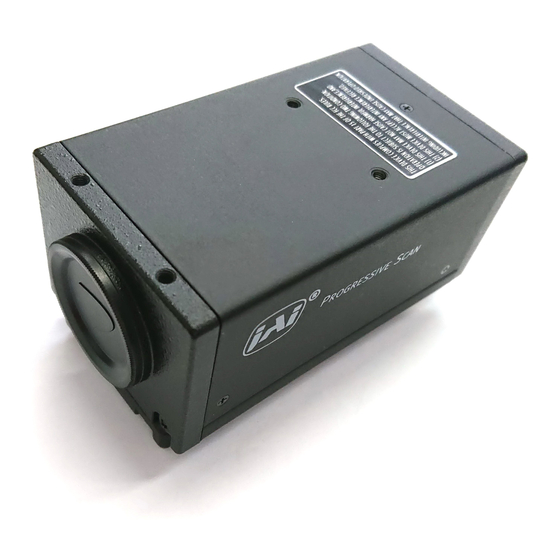
- Page 1 CV-M77 Progressive Scan Camera CV-M77 Operation Manual Camera: Revision A Manual: Version 1.0 - 1 -...
- Page 2 CV-M77 - 2 -...
-
Page 3: Table Of Contents
8.2.2 SW302 switch ... 20 8.2.3 SW303 switch ... 20 Jumper settings ... 21 Jumper locations ... 21 Jumper table... 22 CV-M77 Camera Control Tool... 23 Specifications... 25 11.1 Spectral sensitivity ... 26 Appendix... 27 12.1 Precautions ... 27 12.2 Typical CCD Characteristics ... - Page 4 12.2.4 Patterned Noise ... 27 12.3 References... 27 Users Record... 28 Index... 28 CV-M77 - 4 -...
-
Page 5: General
1 General The CV-M77 camera is a compact RGB color progressive scan camera designed for automated imaging applications. The 1/3" CCD sensor with square pixels and primary mosaic filter offers a superb image quality and the build in DSP assures high color reproduction. -
Page 6: Camera Housing And Dimensions
4 M3 mounting threads. *2) *1) Note: Rear protrusion on C-mount lens must be less than 6mm (0.24-inch approx.) *2) Note: Notice depth of thread is only 5mm. Too long screws may harm inside electronics. CV-M77 4-M3 depth5 (19.7) (0.2) (3.54) 4-M3 depth5 (0.2) -
Page 7: Pin Assignment
Ext.TRIG input EEN output Notes: Signals on pin no. 4 and 6 can be changed by jumper setting. CV-M77 5.1.1.2 Remarks SW-S301.1 “ON” for 75 termination, SW-S303.1 “OFF” for HD output SW-S301.2 “ON” for 75 termination, SW-S303.2 “OFF” for VD output PCLK out: JP305 “short”, JP306 “open”... -
Page 8: 9-Pin Dsub-Connector (Rgb/Sync.)
(input or output) from the 12 pin or 6 pin connectors. Signals shown in bold italics are factory settings. CV-M77 5.3.1.2 Remarks VD input: JP303 “open” and JP304 “short” Sync. on G: SW302-3 “ON”... -
Page 9: Input And Output Circuits
5.4.4 HD, VD, PCLK, WEN and EEN output The output circuits for these signals are 75 complementary emitter followers. The single circuit delivers a TTL signal. The output level 4 V from 75 (no termination). CV-M77 RGB video or 75 Trigger input HD, VD... -
Page 10: Functions And Operation
6 Functions and Operation Apart from the standard continuous operation, the CV-M77 features three external triggering modes, Edge Pre-select, Pulse Width Control mode and Readout Delay mode. These 3 external triggering modes operate with H non-reset. In H non-reset, the exposure will be synchronized to the internal HD and the exposure will start at the first HD after the negative going edge of the trigger (see figure 6-1). -
Page 11: Pulse Width Control Trigger Mode
6-2). Otherwise the jitter will be too high. To use this mode: Set SW1-5,6 and to SW1-7 on the rear plate of the camera to “OFF” or use the RS 232C control. CV-M77 Input Signal Phase Relation Phase Relation of TRIG and EXTHD TRIG... -
Page 12: Frame-Delay Readout Mode
Se figure 6-2 for the phase relationship between ext. HD and ext. VD pulses. To use this mode: Set SW1-1 to SW1-7 on the rear plate of the camera to OFF or use the RS 232C control. Apply the continuous external VD signal. CV-M77 - 12 -... -
Page 13: Timing Diagram For Horizontal And Vertical Sync. Video Output
CV-M77 6.4 Timing diagram for Horizontal and Vertical Sync. Video Output - 13 -... -
Page 14: Timing Diagram For Edge Pre-Select Mode
6.7 Timing diagram for Frame-delay Readout mode TRIG 1H-2000H EXT HD INT HD EXT VD INT VD Delay time Exposure time 0.5H Video out CV-M77 770H Effective video 770H Effective video - 14 - 1H=50.8 s 2H Min 1.5H-2.5H Exposure time 1H=50.8 s 1H Min 0.5H-1.5H... -
Page 15: Timing Diagram For Long Time Exposure Mode
6.8 Timing diagram for Long Time Exposure mode EXT HD INT VD EXT VD INT VD 1H Max Video out CV-M77 1V x N (2VD Min) Exposure time 770H Remarks: 1VD indicates 792H. The interval of EXT VD input has to be multiple number of 1VD. -
Page 16: Configuring The Camera Using The Serial Interface
7.1 Mode Setting using ASCII commands via the RS-232C port. The configuration of the CV-M77 camera can be done via the RS-232C port. The camera is to be set up via an ASCII terminal or from a PC running terminal emulator software. -
Page 17: Receiving Data (Camera->Pc)
Command Error: 01 Unknown Command!!<CR><LF> Parameter Error: 02 Bad Parameters!!<CR><LF> Response to Request Command Example: Request Command (PC→Camera) Command Name Trigger Mode TR?<CR><LF> CV-M77 0=OFF (Manual), 1=ON (Auto) 0-700 0-255 0-255 0-255 0=Manual (Variable) 1=Auto (Variable) 2=4600K (Fixed) 3=5600K (Fixed) -
Page 18: Rs232C Cable Connections
Response to firmware version request command Example: Request Command (PC→Camera) Command Name Version Request VN?<CR><LF> 7.4 RS232C Cable Connections CV-M77 Receiving Data(Camera→PC) Format ***<CR><LF> CAMERA COM PORT 6 PIN 9 PIN D 1 CD 4 DTR 6 DSR 1 TXD... -
Page 19: Switch Settings
Color temperature Composite sync. on green video signal WEN OFF/ON at DSUB connector Input/Output of VD and HD signals 8.2.1 SW301 switch S301 Xxxx Xxxx TRIG: 3 Xxxx Xxxx CV-M77 (>) xxxx < < < < xxxx < < < <... -
Page 20: Sw302 Switch
The SW303 switch switches between output of internal HD/VD signals and input of external HD/VD signals. The factory setting is input of external HD/VD signals (SW303-1 and SW303-2 in “ON” position). The “ON” position is towards switch SW301. CV-M77 - 20 -... -
Page 21: Jumper Settings
The PK8308A board has 12 jumpers of interest: JP301-JP312. Factory setting: At JP301 is mounted a capacitor to protect the trigger circuit against +12V DC. JP303, JP307, JP308, JP309 and JP312 are “short”. JP302, JP304, JP305, JP306, JP310 and JP311 are “open”. CV-M77 JP401 1SS302 02CZ7.5Z SC105 7.5Z... -
Page 23: Cv-M77 Camera Control Tool
CV-M77 10 CV-M77 Camera Control Tool The Camera Control Tool software for the CV-M77 camera is available from the JAI homepage (www.jai.com). The software runs under Windows 98, NT and Windows 2000. The software interface has incorporated all the commands described in the ASCII protocol in an easy to use fashion –... - Page 24 CV-M77 Fig. Windows from the Camera Control Tools software. - 24 -...
-
Page 25: Specifications
Storage temp./humidity Power Lens mount Dimensions Weight Note: Above specifications are subject to change without notice. CV-M77 Progressive 792 lines 24.8 frames/sec. 25.000 MHz 19.685 kHz (1270 pixel clock/line) 24.8 frames/sec. (792 lines/frame) 1/3” RGB primary color IT CCD 4.8 (h) x 3.6 (v) mm... -
Page 26: Spectral Sensitivity
0 . 6 0 . 4 0 . 2 0 . 0 4 0 0 CV-M77 5 0 0 6 0 0 W a v e l e n g t h (n m ) - 26 - IR s t o p... -
Page 27: Appendix
(shown as bright dots) may appear on the image. 12.3 References 1. This manual and the datasheet for the CV-M77 camera can be downloaded from www.jai.com 2. Camera control software is available from www.jai.com 3. Specifications for the ICX204AK CCD sensor can be found via www.jai.com... -
Page 28: Users Record
13 Users Record Camera type: Revision: Serial No. Users Mode Settings Users Modifications 14 Index No index. CV-M77 CV-M77 (Revision A) …………….. - 28 -...
Need help?
Do you have a question about the CV-M77 and is the answer not in the manual?
Questions and answers